Teledyne Photometrics Moment User manual
1
MomentTM Scientific CMOS User Manual
Moment- User Manual

i
MomentTM Scientific CMOS User Manual
© Copyright 2019 Teledyne Photometrics
3440 East Britannia Drive
Tucson, Arizona 85706
Tel: +1 520.889.9933
Fax: +1 520.295.0299
All rights reserved. No part of this publication may be reproduced by any means without the written permission of Teledyne
Photometrics.
Acrobat and Reader are registered trademarks of Adobe Systems Incorporated in the United States and/or other countries.
Teledyne Photometrics and PVCAM are registered trademarks of Teledyne Technologies.
Moment is a trademark of Teledyne Photometrics.
Intel Core is a trademark of Intel Corporation in the U.S. and/or other countries.
Windows is a registered trademark of Microsoft Corporation in the United States and/or other countries. All other brand and
product names are the trademarks of their respective owners and manufacturers.
The information in this publication is believed to be accurate as of the publication release date. However, Teledyne
Photometrics does not assume any responsibility for any consequences including any damages resulting from the use
thereof. The information contained herein is subject to change without notice. Revision of this publication may be issued to
incorporate such change.

ii
MomentTM Scientific CMOS User Manual
LIMITED WARRANTY
Teledyne Photometrics (“Teledyne Photometrics,” us,” “we,” “our”) makes the following limited warranties. These limited
warranties extend to the original purchaser (“You”, “you”) only and no other purchaser or transferee. We have complete
control over all warranties and may alter or terminate any or all warranties at any time we deem necessary.
Basic Limited Two (2) Year Warranty
Teledyne Photometrics warrants this product against substantial defects in materials and/or workmanship for a period of
up to two (2) years after shipment. During this period, Teledyne Photometrics will repair the product or, at its sole option,
repair or replace any defective part without charge to you. You must deliver the entire product to the Teledyne Photometrics
factory or, at our option, to a factory-authorized service center. You are responsible for the shipping costs to return the
product. International customers should contact their local Teledyne Photometrics-authorized representative/distributor for
repair information and assistance, or visit our technical support page at www.photometrics.com.
Limited One (1) Year Warranty on Refurbished or Discontinued Products
Teledyne Photometrics warrants, with the exception of the CMOS or CCD image sensor device (which carries NO
WARRANTIES EXPRESS OR IMPLIED), this product against defects in materials or workmanship for a period of up to one
(1) year after shipment. During this period, Teledyne Photometrics will repair or replace, at its sole option, any defective
parts, without charge to you. You must deliver the entire product to the Teledyne Photometrics factory or, at our option, a
factory-authorized service center. You are responsible for the shipping costs to return the product to Teledyne Photometrics.
International customers should contact their local Teledyne Photometrics representative/distributor for repair information
and assistance or visit our technical support page at www.photometrics.com.
Normal Wear Item Disclaimer
Teledyne Photometrics does not warrant certain items against defect due to normal wear and tear. These items include
internal and external shutters, cables, and connectors. These items carry no warranty, expressed or implied.
Software Limited Warranty
Teledyne Photometrics warrants all of our manufactured software discs or memory devices to be free from substantial
defects in materials and/or workmanship under normal use for a period of one (1) year from shipment. Teledyne Photometrics
does not warrant that the function of the software will meet your requirements or that operation will be uninterrupted or
error free. You assume responsibility for selecting the software to achieve your intended results and for the use and results
obtained from the software. In addition, during the one (1) year limited warranty, the original purchaser is entitled to receive
free version upgrades. Version upgrades supplied free of charge will be in the form of a download from the Internet. Those
customers who do not have access to the Internet may obtain the version upgrades on a CD ROM or USB memory device
from our factory for an incidental shipping and handling charge.

iii
MomentTM Scientific CMOS User Manual
Owner’s Manual and Troubleshooting
You should read the owner’s manual thoroughly before operating this product. In the unlikely event that you should
encounter diculty operating this product, refer to the owner’s manual. If the problem persists, please contact the Teledyne
Photometrics technical support sta or an authorized service representative.
Your Responsibility
The above Limited Warranties are subject to the following terms and conditions:
You must retain your bill of sale (invoice) and present it upon request for service and repairs or provide other proof of
purchase satisfactory to Teledyne Photometrics.
You must notify the Teledyne Photometrics factory service center within thirty (30) days after you have taken delivery of
a product or part that you believe to be defective. With the exception of customers who claim a “technical issue” with the
operation of the product or part, all invoices must be paid in full in accordance with the terms of sale. Failure to pay invoices
when due may result in the interruption and/or cancellation of your two (2) year limited warranty and/or any other warranty,
expressed or implied.
All warranty service must be made by the Teledyne Photometrics factory or, at our option, an authorized service center.
Before products or parts can be returned for service you must contact the Teledyne Photometrics factory and receive a
return authorization number (RMA). Products or parts returned for service without a return authorization evidenced by an
RMA will be sent back freight collect.
These warranties are eective only if purchased from the Teledyne Photometrics factory or one of our authorized
manufacturer’s representatives or distributors.
Unless specified in the original purchase agreement, Teledyne Photometrics is not responsible for installation, setup, or
disassembly at the customer’s location.
Warranties extend only to defects in materials or workmanship as limited above and do not extend to any product or part
which has:
• been lost or discarded by you;
• been damaged as a result of misuse, improper installation, faulty or inadequate maintenance, or failure to follow
instructions furnished by us;
• had serial numbers removed, altered, defaced, or rendered illegible;
• been subjected to improper or unauthorized repair; or
• been damaged due to fire, flood, radiation, or other “acts of God” or other contingencies beyond the control of Teledyne
Photometrics.

iv
MomentTM Scientific CMOS User Manual
After the warranty period has expired, you may contact the Teledyne Photometrics factory or a Teledyne Photometrics-
authorized representative for repair information and/or extended warranty plans.
Physically damaged units or units that have been modified are not acceptable for repair in or out of warranty and will be
returned as received.
All warranties implied by state law or non-U.S. laws, including the implied warranties of merchantability and fitness for a
particular purpose, are expressly limited to the duration of the limited warranties set forth above. With the exception of
any warranties implied by state law or non-U.S. laws, as hereby limited, the forgoing warranty is exclusive and in lieu of all
other warranties, guarantees, agreements, and similar obligations of manufacturer or seller with respect to the repair or
replacement of any parts. In no event shall Teledyne Photometrics’ liability exceed the cost of the repair or replacement of
the defective product or part.
This limited warranty gives you specific legal rights and you may also have other rights that may vary from state
to state and from country to country. Some states and countries do not allow limitations on how long an implied warranty
lasts, when an action may be brought, or the exclusion or limitation of incidental or consequential damages, so the above
provisions may not apply to you.
When contacting us for technical support or service assistance, please refer to the Teledyne Photometrics factory of
purchase, contact your authorized Teledyne Photometrics representative or reseller, or visit our technical support page at
www.photometrics.com.
U. S. Government Restricted Rights
The software and documentation are provided with Restricted Rights. Use, duplication, or disclosure by the Government is
subject to restrictions as set forth in subparagraph (c)(1)(ii) of the Rights in Technical Data and Computer Software clause
at DFARS 252.227-7013 or subparagraphs (c)(1) and (2) of the Commercial Computer Software-Restricted Rights at 48 CFR
52.227-19, as applicable. Contractor/manufacturer is Teledyne Photometrics, 3440 East Britannia Drive, Tucson, AZ 85706.
This license is eective until terminated. It will terminate upon the conditions set forth above or if you fail to comply with
any term hereof. Upon termination, you agree that the software and accompanying materials, and all copies thereof, will
be destroyed. This agreement is governed by the laws of the State of Arizona. You acknowledge that you have read this
agreement, you understand it, you agree to be bound by its terms, and that this is the complete and exclusive statement of
the agreement between you and Teledyne Photometrics regarding the software.

v
MomentTM Scientific CMOS User Manual

vi
MomentTM Scientific CMOS User Manual
Table of Contents
Chapter 1 - Overview 1
About This Manual 1
Precautions 1
Environmental Requirement 2
Storage Requirements 2
Microscopes, Lenses, and Tripods 2
Repairs 2
Cleaning 2
Chapter 2 - System Installation 3
Introduction 3
Software Compatibility 3
Host Computer Requirements 3
Software Installation 3
Installing the USB card 4
Connecting the USB cable 5
Chapter 3 - Theory of Operation 6
CMOS Image Sensor Structure 6
Digital Binning 7
Pixel Noise Filters 7
Trigger Modes 9
Expose Out Behaviour 9
Cooling 9
Chapter 4 - Basic Specifications 10

1
MomentTM Scientific CMOS User Manual
1
Chapter 1 - Overview
The Moment CMOS user manual is divided into 3 chapters. Teledyne Photometrics
recommends you read the entire manual before operating the camera to ensure
proper use. The chapter contents are briefly described below.
Note: The information provided applies only to the Moment CMOS camera and is
not applicable to any other Teledyne Photometrics camera.
System Installation – Instructions on how to connect the camera to the
computer via the USB 3.2 Gen2 interface
Theory of operation – A basic overview of CMOS technology as used in
the Moment CMOS
Basic specifications – specifications for the Moment CMOS
The CMOS sensor and other system electronics are extremely sensitive to
electrostatic discharge (ESD). To avoid permanently damaging the system, please
observe the following precautions:
1. If using high-voltage equipment (such as an arc lamp) with the camera
system, turn the camera power on last and when powering down, power the
camera o first.
2. Use caution when triggering high-current switching devices (such as an arc
lamp) near the system. The image sensor can be permanently damaged
by transient voltage spikes. If electrically noisy devices are present, an
isolated, conditioned power line or dedicated isolation transformer is highly
recommended.
3. Always leave one inch of space around the camera for airflow.
4. Never open the camera. There are no user-serviceable parts inside the
Moment CMOS camera. Opening the camera voids the warranty
5. Use only the interface card, cables and power supply designated for this
camera system. Using non-Moment cables, interface cards or power supplies
may result in unexpected errors or permanent damage to the system
6. Do not use a C-mount lens with optics that extend behind the lens flange
About This Manual
Precautions

2
MomentTM Scientific CMOS User Manual
The Moment CMOS camera should be operated in a clean, dry environment.
The camera system should not be operated without being attached to a lens
or microscope without proper airflow around the camera. The camera system’s
ambient operating temperature is 0°C to 30°C with 80% relative humidity, non-
condensing.
The CMOS sensor and other system electronics are extremely sensitive to
electrostatic discharge (ESD). To avoid permanently damaging the system, please
observe the following precautions:
The camera has two standard mounting options and can be coupled to any
optical system or microscope that accepts a standard C-mount adapter for the
Moment. The camera also allows you to install any lens that is compatible with
either of these threaded video mounts if its optics do not extend behind the
flange of the lens. Moment can be mounted to optical tables, tripods or custom
stands using M3 screws threaded attachment points located near the front of the
camera housing on all sides.
Please save the original packing materials so you can safely ship the camera to
another location or return it for repairs if necessary. The Moment CMOS camera
system contains no user-serviceable parts. Repairs must be done by Teledyne
Photometrics. Should the camera system require repairs, please contact Teledyne
Photometrics Customer Service.
Note: Do not open the camera. Opening the Moment CMOS voids the warranty.
Clean exterior surfaces of the camera with a dry, lint-free cloth. To remove
stains, contact Teledyne Photometrics Customer Service. To clean the camera’s
imaging window, use only a filtered compressed-air source. Hand-held cans are
not recommended as they may spray propellant onto the window. Do not touch
the window.
Environmental Requirements
Storage Requirements
Microscopes, Lenses, and
Tripods
Repairs
Cleaning

3
MomentTM Scientific CMOS User Manual
Carefully review the Precautions section in the previous chapter before
performing any of the procedures outlined in this chapter. Using a dierent
cable or interface card may result in permanent damage to the system
The Moment CMOS camera system includes the following hardware components:
• Moment CMOS Camera
• USB Interface Card
• USB cable
• Two single-line MMCX trigger cables
• USB memory device containing PVCAM library and drivers
• Quick Installation Guide
The Moment camera is powered over the USB 3.2 Gen2 connection. While it is
recommended that the camera is operated via the USB interface card, the camera
can also run on a PCs native USB 3.0 port. All of these hardware components
should be included with the shipment. Keep all the original packing materials
so you can safely ship the camera to another location or return it for service.
If you have any diculty with any step of the instructions, contact Teledyne
Photometrics Customer Service.
Unless there is a preferred version specified by a third party software provider, the
latest version of PVCAM is recommended for use with the Moment camera. The
PVCAM SDK is available on the company website.
The host computer (PC) for Moment must meet the following minimum
requirements:
• Windows 10 64-bit operating system
• 2.0 GHz or faster Intel processor: either Xeon or Core i7
• 8+ GB RAM
• 250+ GB serial ATA (SATA) HDD and/or >512 GB solid state drive (SDD) for
high-speed imaging and storage
• 512+ MB slot-based ATI/NVIDIA video graphics card (i.e., not an “onboard/
integrated graphics” adapter)
• USB port for use with the USB memory device or Internet access to obtain
the PVCAM library and interface drivers
• An open PCI-Express 4x (4 lane) interface slot or higher for use with the USB
3.2 Gen2 interface card
Introduction
Software Compatibility
Host Computer Requirements
Chapter 2 – System Installation
4
MomentTM Scientific CMOS User Manual
An appropriate Installation Guide is included as an insert with the camera. This
guide provides step-by-step instructions for installing the camera interface
software for Windows-based computers. Additional instructions are included for
installing a PCI Express interface card in the computer. The Teledyne Photometrics
USB memory device contains the following files:
• Manuals Directory — contains user manuals in PDF format.
• Customer Case Studies — application examples
• Imaging Software – a copy of Open Imaging’s Microscopy Application:
Micromanager
• Technical Notes – detailed background on advanced features
For a 64-bit Windows OS, install PVCam64_Setup_X_X_X_X.exe (latest version
is on drive)
For a 32-bit Windows OS, install PVCam32_Setup_X_X_X_X.exe (latest version
is on drive)
Follow the Installation Guide insert for the version of Windows being used.
Reboot the computer when the installation is complete.
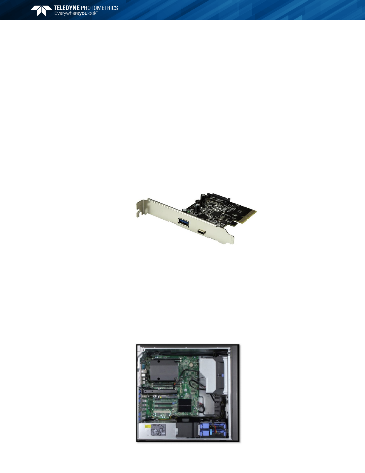
The USB 3.1 card included with the Moment camera ensures a stable connection
and maximum data is able to be acquired from the camera.
Note: The model of USB card shipped with the camera may dier from the one
shown in the photo. Please refrain from using other cards, as they may damage
the camera.
Before attempting to operate the camera, first install this interface card into the
PC with the following steps:
1. Shut down the PC
2. Unplug the PC from power mains and ensure the camera is turned o
3. Open the side of the computer to access the PCI and PCIe slots
Software Installation
Installing the USB card
5
MomentTM Scientific CMOS User Manual
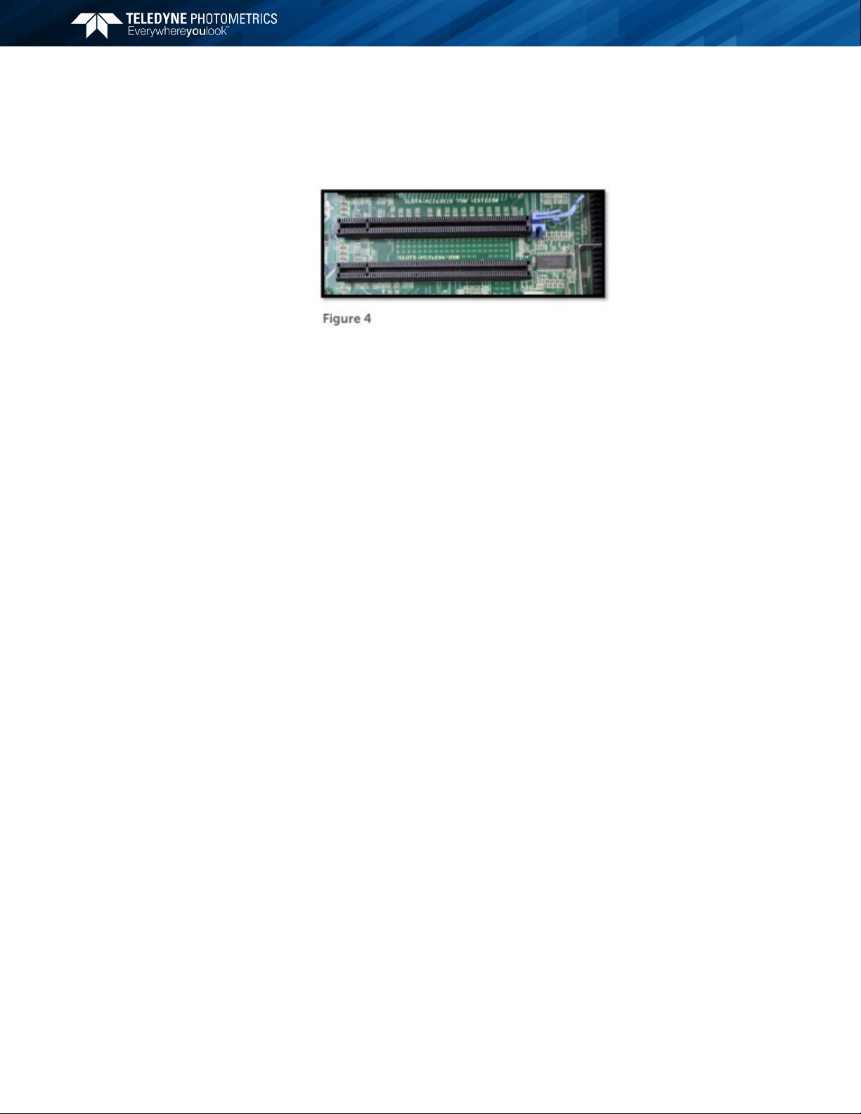
4. Locate an available 4 channel or higher PCIe slot (marked x4). Refer to the PC’s
documentation to locate a suitable slot.
5. Holding the USB card and (being careful not to touch the board components
or PCIe bridge pins) insert it with the proper orientation into the open slot. The
card should slide into place with minimal resistance and snap when fully inserted.
Once the USB cable has been connected to the camera and host PC, the camera
will power on. When using 3 meter active cables, it is important that proper USB
cable orientation is used. Please refer to the quickstart guide with the camera or
the USB stick for the most up to date instructions.
Connecting the USB cable

6
MomentTM Scientific CMOS User Manual
A major dierence between traditional CCD sensors and CMOS sensors is the
location where charge-to-voltage conversion of accumulated photoelectrons
takes place. CCD sensors transfer the pixels accumulated signal in charge packets
in “bucket brigade” fashion across the sensor to a common output node where
charge is converted to a voltage. The voltage is then sampled using o-chip
Analog-to-Digital Converters (ADC) and transferred to the PC as digital grey
values.
While providing excellent quantitative photometry and very high image quality,
the large number of transfers and sequential digitization of pixels results in low
frame rates. This speed penalty increases with the number of pixels to be digitized.
CMOS sensors leverage many of the same analog signal concepts used in CCDs,
but places the output node circuitry inside each pixel. This eliminates the charge
transfer process. To read the signal from a given row, the accumulated charge is
converted to a voltage inside the pixel, then each pixel in the row is connected
to the appropriate column voltage bus, where the on-chip ADCs covert the
voltages to an 12-bit grey value. (Thus far, the on-chip ADCs available on CMOS
sensors have limited dynamic range.) The parallel digitization of all pixels in a
row provides CMOS devices with a tremendous speed advantage. Imagine a CCD
with 2048x2048 pixels – and each pixel’s voltage is measured in 1 μsec. To read
a single row, 2048 voltage measurements are performed in serial fashion taking
slightly longer than 2 ms,and when repeated for 2048 rows, the entire image
takes over four seconds tobe digitized.
On this CMOS device – the entire 2200 voltage conversions needed to digitize
a row happen in parallel. The sensor in the Moment CMOS camera takes
parallelism even further by dividing the sensor into two halves, so that two rows
of 2048 pixels can be measured at the same time. If the time to digitize a pixel
remains at 1 us – the time to read the entire frame is now ~ 1 ms. In practice,
the time saving is split between faster frame rates and slowing the rate of pixel
measurement to reduce electronic noise. For example, if the time to measure a
pixel was increased to 10 μsec to lower noise, the image sensor can still be read
in 10 ms (for a maximum 100fps).
Of course, there are many challenges to obtaining the same analog performance
from each of Moment’s 7 million pixels, whereas a CCD has a single, common
output node resulting in a uniform response. The most common problems are
pixel-to-pixel non uniformity in gain and oset, random telegraph noise (RTN),
and defective pixels with abnormal noise or dark current characteristics (hot
pixels). Often solutions to these challenges are found in the digital domain, where
Moment’s advanced real time signal processing corrects each pixel for gain and
oset variation using calibration at the factory. To address RTN and other pixel
defects, real-time digital filters are used. These corrections are described further
in this manual.
CMOS Image
Sensor Structure
Chapter 3 – Theory of Operation

7
MomentTM Scientific CMOS User Manual
CCD image sensors are capable of charge binning (combining adjacent pixels into
one super pixel). This is accomplished as part of the charge transfer process and
has the advantage of increasing signal to noise in read-noise limited situations, at
the expense of spatial resolution.
The lack of a charge transfer process in CMOS devices means true charge
binning is not available in currently available Scientific CMOS sensors. Even so,
co-adding pixels is a convenient means to reduce image data, or increase signal
by 4x and improve SNR by 2x as the noise from each pixel adds in quadrature.
Moment includes 2x2 on-camera simulated binning, done on the FPGA. This
mathematically combines signal from adjacent pixels and adjusts the sum so that
the bias oset is only added one time.
Note: The Moment CMOS camera ships with an optimized default setting for
Real Time Pixel Noise Filtering. Normally these values do not need to be adjusted.
Additionally, the features described in this section may not be controllable in the
software application. This is an advanced usage section..
In the CMOS sensor section, it was noted that a drawback to current CMOS sensors
is variability in pixel to pixel response. This variability falls into two categories,
static variation in gain and oset and dynamic fluctuations that require real-time
Pixel Noise Filters, also known as “Despeckling”.
The static variation in gain and oset is measured and a correction factor
is determined for every pixel. This fixed pattern noise is measured during
manufacture and the corrections are stored in the camera. These corrections are
then applied in real-time to each image.
The dynamic fluctuations must be detected and corrected in real-time. The
Moment has several noise filters for this purpose. Defect detection is based on
use of a conditional median filter. The 3x3 neighborhood surrounding a pixel
is examined. If the pixel’s value exceeds or falls below the median by a given
amount, its value is replaced by the median. Four filters are available:
Real-time Filters for Random Telegraph Noise:
1. Despeckle Dark Low
2. Despeckle Bright Low
Real-time Filters for Bright (Hot) or Dark Pixels:
3. Despeckle Dark High
4. Despeckle Bright High
Digital Binning
Pixel Noise Filters
8
MomentTM Scientific CMOS User Manual
“Dark” filters work on the low side of the local median, while “Bright” filters work
on the high side of the local median. The filter is only applied if the pixel’s value
exceeds (or is below) a threshold expressed as a percent of the local median x100.
For example, a Despeckle Dark Low threshold of “97” indicates that a pixel that is
3% below the local median will be replaced with the local median. A Despeckle
Bright High threshold of “300” indicates that a pixel that is 200% brighter than the
local median will be replaced.
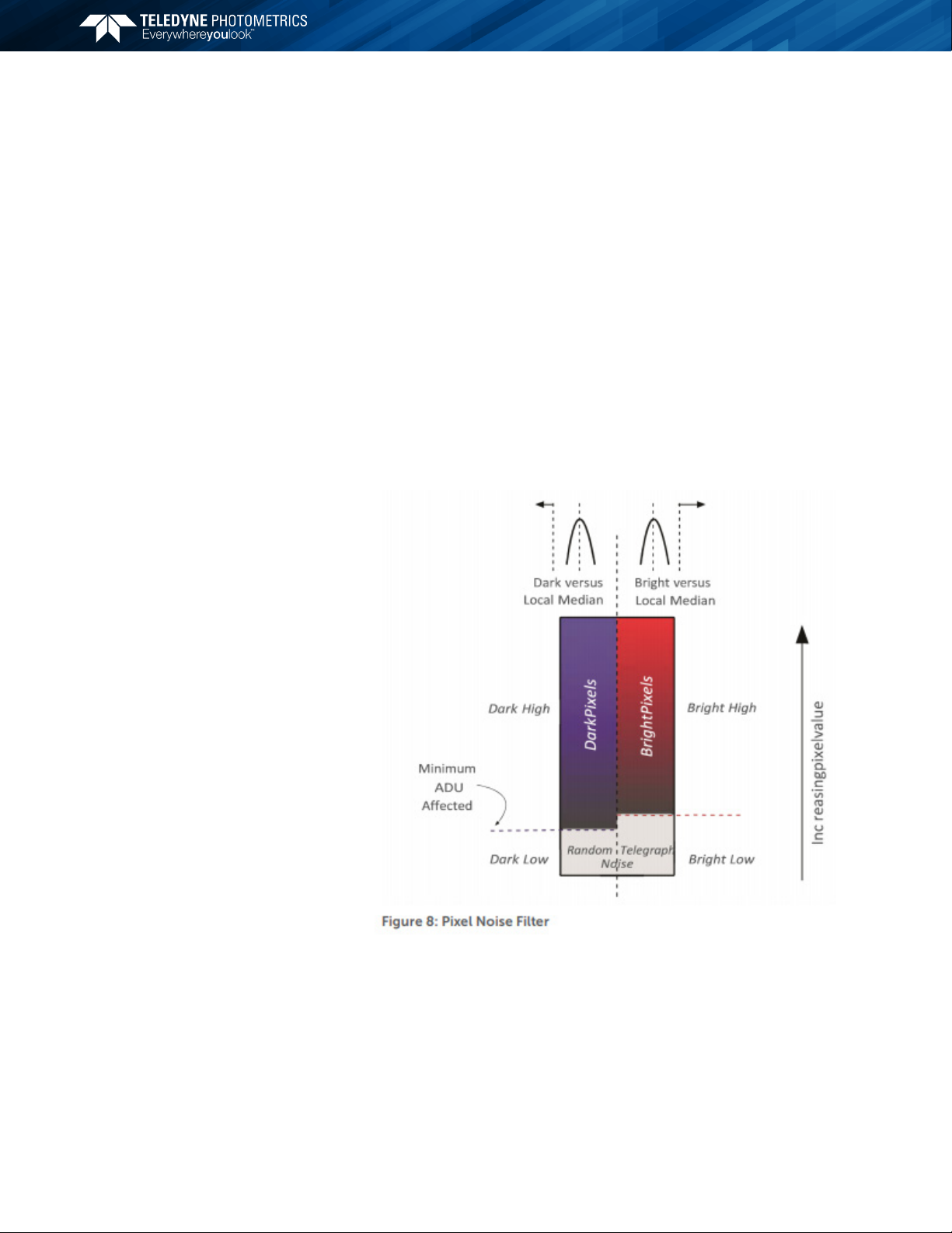
The intensity range where each filter operates can be set by a value known as
“Minimum ADU AFFECTED”. Take the “Dark” filters for example – pixel values that
fall below the Minimum ADU Aected will be operated on using Despeckle Dark
Low, and pixel values that lie above the Minimum ADU Aected will be operated
on using Despeckle Dark High settings.
Given the new terminology – a simplified way to visualize the region in which
each filter operates is shown below:
The general principle for setting the pixel noise filters is to use as little filtering as
possible. Often the best way to determine this is viewing a real-time histogram
with log scaling of the frequency. For setting “Dark Low” and “Bright Low”, block
any light from reaching the sensor and examine the bias histogram. This allows
viewing the histogram’s tail, where the eect of the filters can be seen. Adjust the
filters to trim the non-Gaussian tails from the distribution. For “Dark High” and
“Bright High”, observe the image with flat, even illumination in the expected range
to be observed. Adjust “Bright High” to eliminate most of the bright speckles, and
adjust “Dark High” to eliminate any dark speckles that might appear.

9
MomentTM Scientific CMOS User Manual
Timed Mode
Timed mode is the default triggering mode for Moment. This means, the software/
application initiates the start of a sequence of acquisitions. Once initiated, each
frame captured in the sequence is controlled by the internal timing generators
of the camera. Camera settings, expose out behaviour and sequence size are set
in the software application prior to acquiring the sequence. Timed mode is used
when synchronization with other devices is either not required or is controlled
independently through the software.
Edge Mode
Like Trigger-First Mode, Edge Mode requires a hardware trigger but this time for
every frame. The rising edge of the external trigger initiates capture of a single
frame. Each frame requires an external trigger from the I/O connector. Camera
settings, expose out behaviour and sequence size is set in the software application
prior to acquiring the sequence.
The Moment is a global shutter camera. This means that all pixels are electronically
shuttered to be receiving light at the same time. As a result, the expose out signal,
designed to trigger light sources to only illuminate when the camera is ready,
demonstrates straightforward behaviour. The benefit of a global shutter is that no
rolling shutter eects are present, such as image distortion on moving samples.
The Moment CMOS is an uncooled camera. A micro-fan is part of the camera
assembly, and is used to move heat away from the camera boards. It is advised
to have the camera attached to either a lens or a microscope while the camera
is in use.
Trigger Modes
Expose Out Behaviour
Cooling
10
MomentTM Scientific CMOS User Manual
Chapter 4 – Basic specifications
Frame Rate
Array Size Speed
3200 x 2200 51
3200 x 1100 100
3200 x 550 193
3200 x 275 353
3200 x 8 1814
3200 x 2 2074
Specifications Camera Performance
Sensor Photometrics Sony-based Scientific CMOS
Active Array Size 3200 x 2200 (7 Megapixel)
Pixel Area 4.5μm x 4.5μm
Sensor Area 14.4mm x 9.9mm, 17.5mm diagonal
Peak QE% 73%
Read Noise 2.2 e-
Full-Well Capacity 8200e-
Framerate (full-frame) 50 fps
Bit Depth 12-bit
Shutter Type Global Shutter
Cooling Uncooled
Interface USB 3.2 Gen 2 (10 Gbps)
Triggers 1 Input
1 Output

11
MomentTM Scientific CMOS User Manual
Chapter 4 – Basic specifications

12
MomentTM Scientific CMOS User Manual
www.photometrics.com
Main Phone: +1 520.889.9933
Support: +1 604.530.5800 / +1 800.874.9789
Rev A0-09072020
Table of contents
Other Teledyne Photometrics Digital Camera manuals


Popular Digital Camera manuals by other brands

Sony
Sony Cyber-shot DSC-WX350 instruction manual

Samsung
Samsung DV150F 16.2MP Smart Compact Camera (WiFi user manual

Hidden
Hidden 208119 user manual

FujiFilm
FujiFilm Finepix 4900 Zoom Brochure & specs

Panasonic
Panasonic Lumix DMC-ZS20 Basic owner's manual

Brickcom
Brickcom OSD-200Np-S 30X Easy installation guide


