Teledyne GaN PowerMAX User manual

PAGE 1 OF 16 214578 REV A ECO 18422
GaN PowerMAX
Second Generation GaN
Modular N+1 Phase Combined System
FEATURES
• Gallium Nitride amplifiers, offering
better power over frequency
• Output Power levels of up to:
10 kW in S-, C- and X-Bands;
5.8 kW in Ku-Band
• No Active Switching-All Passive
Power Combining
• System is 100% field maintainable
• Output Power sized for N+1
Redundancy
• All active modules are hot swappable
via the front or rear panels
• System can be configured with any
combination of 4 to 16 modules.
• Hot Swappable Redundant Power
Supply Modules
• Hot Swappable SSPA Modules
• Removable Fan Trays
• Removable M&C Card Assembly
• System monitor and control emulates
single SSPA Chassis operation
• Ethernet Port with UDP, SNMP, and
internal web browser capability
• Legacy RS-485 M&C
• Accurate Output Power Measurement
• Reflected Power Monitor
• RF Output Sample Port
• RF Gain Adjustment
(42 dB - 62 dB) Ku-Band systems
(50 dB - 70 dB) all others
• System is field scalable: i.e., can start
out with (4) modules in system and
upgrade to (8) or (16) modules.
The New Standard in High Power Redundant
Microwave Amplifier Systems Has Arrived
2.5 kW Ku-Band Solid State High Power Amplifier System
configured with (8) Modules
Teledyne Paradise Datacom Teledyne Paradise Datacom Ltd.
328 Innovation Blvd., Suite 100 2&3 The Matchyns, London Road, Rivenhall End
State College, PA 16803 USA Witham, Essex CM8 3HA United Kingdom
Tel: 1 (814) 238-3450 Tel: +44(0) 1376 515636
Fax: 1 (814) 238-3829 Fax: +44(0) 1376 533764
www.paradisedata.com
PowerMAX is covered by U.S. Patent Nos.
8,189,338 B2 and 8,411,477 B2

PAGE 2 OF 16 214578 REV A ECO 18422
GaN PowerMAX
Second Generation GaN
Modular N+1 Phase Combined System
System Operation
The PowerMAX system maintains complete parallel redundancy down to
the embedded control level. Therefore the loss of an entire HPA chassis will
not interrupt remote communications with the system. Remote communica-
tions can be either RS-485 or Ethernet. The system will automatically
correct its gain level in the event of one or more HPA chassis failures.
The sophisticated system monitor and control allows the system to be
locally or remotely operated as if it were a “single” chassis amplifier. The
system control maintains a hierarchical management that allows the
operator to interface to a single chassis of the multi-module array.
Another feature unique to Teledyne Paradise Datacom’s PowerMAX is the
introduction of “true rms” output power measurement. Unlike other amplifier
systems that utilize diode detection schemes, the PowerMAX reports the
true rms output power of the system independent of the number of carriers
and modulation schemes.
Proprietary waveguide combining techniques are employed so that
maximum power combining efficiency is optimized within the operating
frequency band.
System Output Power and Configurations
Because the system power combining is purely passive and no switching is used, there is never an
interruption in RF output power. The PowerMAX system is typically used as a “self-redundant”
system. The output power is sized such that the loss of (1) RF module’s power will still allow the
system to maintain its minimum required output power. This type of system architecture is described
as n+1 redundant. The system can be configured with any number of modules but best overall
efficiency is obtained with the popular binary combinations of 4, 8, or 16 modules. It is very easy to
upgrade the PowerMAX system from 4 modules to 8 or 16 modules in the field. It is not necessary to
fully populate the system at the time of initial purchase. This provides the user a path to upgrade
output power capability as system requirements grow, thus keeping capital investment minimized.
For sizing redundant output power capability use the following guideline to determine the output
power of the system with the loss of (1) module.
4 Module System - 3 of 4 Modules Operable = 2.5 dB loss in output power capability
8 Module System - 7 of 8 Modules Operable = 1.2 dB loss in output power capability
16 Module System - 15 of 16 Modules Operable = 0.6 dB loss in output power capability

PAGE 3 OF 16 214578 REV A ECO 18422
GaN PowerMAX
Second Generation GaN
Modular N+1 Phase Combined System
System Prime Input Power
Proprietary adaptive bias techniques are utilized to achieve
an aggressive balance between RF output power and mini-
mized DC input power.
Prime power may be introduced into a terminal block at the
top of the cabinet. Electrical conduit is routed between the
terminal block and a 5RU boxed assembly, the AC Distribu-
tion/Circuit Breaker Panel, which houses a separate toggle
switch circuit breaker for each power supply module in the
system. Additional circuit breakers are available for auxiliary
equipment mounted in the cabinet.
System prime input power is achieved with an array of mod-
ular (hot-swap) power supply chassis. Power is distributed
from the power supplies to the SSPA modules via a bus rail
assembly.
Each of the power supply modules has its own single
phase, 180-264 VAC input. This makes it very convenient
to parallel the AC inputs of two modules and connect the
array to a three phase AC input source.
The power supply chassis is configured as a n+1 redun-
dant, hot swappable power supply. In the event of a power
supply module failure, the amplifier system will not fail. The
failed module can be changed without ever taking the HPA
out of service. The microwave amplifier architecture is also
designed for maximum soft fail redundancy.
Prime system AC Input Power specifications are shown on
pages 6-8 for various PowerMAX power levels and configu-
rations.
Quick Connect Plug into Bus Rail
Power Supply Module in Chassis
Circuit Breaker Panel
Terminal Block

PAGE 4 OF 16 214578 REV A ECO 18422
GaN PowerMAX
Second Generation GaN
Modular N+1 Phase Combined System
Hitless Redundancy
For mission critical systems in which no power outage
can be tolerated, an eight module PowerMAX system
can be operated with only four modules installed. In this
way, the additional four modules can be installed without
requiring the system to be powered off.
The only disadvantage of operating the eight module
PowerMAX system with four modules is the additional
3 dB loss that the four module (half-system) system
experiences by going through the final hybrid combiner
as shown at right. Therefore the overall output power is
actually 6 dB below what it would be with all eight
modules present in the system.
If, however, the module output power is sized such that
this reduction in output power can be tolerated, the
system shown at right is an effective means of scaling
the system from four to eight modules and maintaining
true hitless operation. The system never has to be
powered down and there are no mechanical switches
involved that would create an interruption of service.
With parallel system architectures, the amplifier output power capability and gain will change as the
number of active modules vary. The PowerMAX system is designed with an Auto-Gain Control mode
so that the overall system gain will remain constant in the event of a single module failure. See the
table below.
2
Σ
1
3
4
RF
OUT
Power
Detector
Module
Chassis
Module
Chassis
Module
Chassis
Module
Chassis
2
Σ
1
3
4
Shorting plate on each
waveguide extension
ΣΔ
IN
IN
4-Way
Combiner
4-Way
Combiner
2-Way
Combiner
System
Type # Modules
in System Gain Change
Auto Gain Control On Gain Change
Auto Gain Control Off Maximum
Output Power
8-Chassis 7 of 8 0 dB -1.2 dB -1.2 dB
8-Chassis 6 of 8 0 dB -2.4 dB -2.4 dB
8-Chassis 5 of 8 0 dB -4.0 dB -4.0 dB
8-Chassis 4 of 8 -1.0 dB -6.0 dB -6.0 dB
8-Chassis 3 of 8 -3.5 dB -8.5 dB -8.5 dB
8-Chassis 2 of 8 -7.5 dB -12.5 dB -12.5 dB
16-Chassis 15 of 16 0 dB -0.6 dB -0.6 dB
16-Chassis 14 of 16 0 dB -1.2 dB -1.2 dB
16-Chassis 13 of 16 0 dB -2.0 dB -2.0 dB
16-Chassis 12 of 16 0 dB -2.5 dB -2.5 dB
4-Chassis 3 of 4 0 dB -2.5 dB -2.5 dB
4-Chassis 2 of 4 -1.0 dB -6.0 dB -6.0 dB
4-Chassis 1 of 4 -7.0 dB -12.0 dB -12.0 dB

PAGE 5 OF 16 214578 REV A ECO 18422
GaN PowerMAX
Second Generation GaN
Modular N+1 Phase Combined System
SSPA Chassis Population Options
The PowerMAX system is available in a variety of system GaN module configurations and output
power levels. The system is based on Teledyne Paradise Datacom’s 3RU chassis with 100% hot
swappable active assemblies. The units can be configured with a wide variety of SSPA frequency
bands and power levels, and can be fitted with the following SSPA modules:
• S-Band: 50W, 100W, 200W, 300W, 400W, 500W, 600W, 800W, 1 kW
• C-Band: 50W, 100W, 150W, 200W, 300W, 400W, 650W, 800W
• X-Band: 300W, 400W, 650W, 800W
• Ku Band: 50W, 80W, 100W, 150W, 200W, 300W, 400W, 500W
Removable rear panel monitor
and control card
Removable front panel fan tray Removable rear panel fan tray
SSPA Module Removal via the front panel
Hot-Swap Chassis Features

PAGE 6 OF 16 214578 REV A ECO 18422
GaN PowerMAX
Second Generation GaN
Modular N+1 Phase Combined System
4 Module C-Band PowerMAX System Power Specifications
SSPA
Module
Power
Level
4 Module
RF Output Power AC Input
Power (W) 3 Module Redundant
RF Output Power
Psat, typical
dBm (W) PLinear, min.
dBm (W) Psat / PLinear Psat / PLinear Psat, typical
dBm (W) PLinear, min.
dBm (W)
50 W 52.5 (178) 49.5 (89) 2,000/1,600 4,900/3,800 50.1 (102) 47.0 (50)
100 W 55.5 (355) 52.5 (178) 2,400/2,000 5,440/4,350 53.1 (204) 50.1 (102)
150 W 57.3 (537) 54.3 (269) 4,000/3,200 9,233/7,057 54.9 (309) 51.9 (155)
200 W 58.5 (708) 55.5 (355) 4,400/3,520 9,797/7,404 56.0 (398) 53.0 (200)
300 W 60.0 (1000) 57.0 (501) 6,000/5,200 13,000/10,800 57.8 (603) 54.9 (302)
400 W 61.5 (1413) 58.5 (708) 7,200/6,400 15,200/13,000 59.1 (813) 56.1 (407)
650 W 63.6 (2291) 60.6 (1148) 13,200/11,200 28,800/23,400 61.2 (1318) 58.2 (661)
800 W 64.5 (2818) 61.5 (1413) 16,000/14,000 35000/29400 62.1 (1622) 59.1 (813)
Heat Load
(Btu/hr)
4 Module S-Band PowerMAX System Power Specifications
SSPA
Module
Power
Level
4 Module
RF Output Power AC Input
Power (W) 3 Module Redundant
RF Output Power
Psat, typical
dBm (W) PLinear, min.
dBm (W) Psat / PLinear Psat / PLinear Psat, typical
dBm (W) PLinear, min.
dBm (W)
50 W 52.6 (180) 49.6 (90) 1,600/1,200 3,740/2,950 50.2 (104) 47.2 (52)
100 W 55.1 (320) 52.1 (160) 2,000/1,600 4,350/3,800 52.7 (184) 49.7 (92)
200 W 58.1 (638) 55.1 (320) 3,200/2,800 8,700/8,000 55.7 (367) 52.7 (184)
300 W 59.9 (970) 56.9 (484) 5,200/4,000 10,858/9,200 57.5 (560) 54.5 (280)
400 W 61.1 (1280) 58.1 (638) 6,400/5,200 13,000/12,000 58.7 (733) 55.7 (367)
500 W 62.1 (1600) 59.1 (803) 7,200/6,000 14,000/13,500 59.7 (923) 56.7 (462)
600 W 63.1 (2000) 60.1 (1000) 8,800/6,800 17,000/15,000 60.7 (1100) 57.7 (582)
800 W 64.1 (2570) 61.1 (1288) 10,000/8,000 18,000/17,000 61.7 (1500) 58.7 (733)
Heat Load
(Btu/hr)
1000 W 65.1 (3200) 62.1 (1600) 16,000/14,000 32,600/31,000 62.7 (1800) 59.7 (923)

PAGE 7 OF 16 214578 REV A ECO 18422
GaN PowerMAX
Second Generation GaN
Modular N+1 Phase Combined System
4 Module X-Band PowerMAX System Power Specifications
SSPA
Module
Power
Level
4 Module
RF Output Power AC Input
Power (W) 3 Module Redundant
RF Output Power
Psat, typical
dBm (W) PLinear, min.
dBm (W) Psat / PLinear Psat / PLinear Psat, typical
dBm (W) PLinear, min.
dBm (W)
300 W 60.2 (1047) 57.2 (525) 6,000/5,200 13,034/10,858 57.8 (603) 54.8 (302)
400 W 61.4 (1380) 58.4 (692) 8,000/6,800 17,428/14,165 59.0 (794) 56.0 (398)
650 W 63.5 (2239) 60.5 (1122) 13,200/11,200 28,879/23,439 61.1 (1288) 58.1 (646)
800 W 64.4 (2754) 61.4 (1380) 16,000/14,000 34,880/29,438 62.0 (1585) 59.0 (794)
Heat Load
(Btu/hr)
4 Module Ku-Band PowerMAX System Power Specifications
SSPA
Module
Power
Level
4 Module
RF Output Power AC Input
Power (W) 3 Module Redundant
RF Output Power
Psat, typical
dBm (W) PLinear, min.
dBm (W) Psat / PLinear Psat / PLinear Psat, typical
dBm (W) PLinear, min.
dBm (W)
50 W 52.3 (170) 49.3 (85) 2,400/2,000 5,983/4,900 50.0 (100) 47.0 (50)
80 W 54.3 (269) 51.3 (135) 2,920/2,340 7,078/5,501 51.9 (155) 48.9 (78)
100 W 55.3 (339) 52.3 (170) 3,000/2,550 9,233/7,601 52.9 (195) 49.9 (98)
150 W 57.1 (513) 54.1 (257) 4,800/3,680 11,409/8,363 54.7 (295) 51.7 (148)
200 W 58.3 (676) 55.3 (339) 9,200/8,000 22,853/19,000 56.0 (398) 53.0 (200)
300 W 60.1 (1023) 57.1 (513) 11,000/8,400 22,600/19,600 57.7 (589) 54.7 (295)
400 W 61.3 (1350) 58.3 (676) 12,800/9,600 30,500/22,000 58.9 (776) 55.9 (389)
500 W 62.3 (1698) 59.3 (851) 16,000/12,000 38,000/27,000 60.0 (1000) 57.0 (501)
Heat Load
(Btu/hr)

PAGE 8 OF 16 214578 REV A ECO 18422
GaN PowerMAX
Second Generation GaN
Modular N+1 Phase Combined System
8 Module C-Band PowerMAX System Power Specifications
SSPA
Module
Power
Level
8 Module
RF Output Power AC Input
Power (W) 7 Module Redundant
RF Output Power
Psat, typical
dBm (W) PLinear, min.
dBm (W) Psat / PLinear Psat / PLinear Psat, typical
dBm (W) PLinear, min.
dBm (W)
50 W 55.0 (316) 52.0 (158) 4,000/3,200 9,790/7,613 53.8 (240) 50.8 (120)
100 W 58.3 (676) 55.3 (339) 4,200/3,500 9,520/8,500 57.1 (513) 54.1 (257)
150 W 60.0 (1000) 57.0 (501) 8,000/6,400 18,466/14,114 58.8 (759) 55.8 (380)
200 W 61.5 (1413) 58.5 (708) 8,800/7,040 19,590/14,807 60.3 (1072) 57.3 (537)
300 W 63.0 (1995) 60.0 (1000) 12,000/10,400 26,000/21,700 61.9 (1549) 58.9 (776)
400 W 64.3 (2692) 61.3 (1349) 14,400/12,800 30,500/26,153 63.1 (2042) 60.1 (1023)
650 W 66.4 (4365) 63.4 (2188) 26,400/22,400 57,750/46,880 65.2 (3311) 62.2 (1660)
800 W 67.3 (5370) 64.3 (2692) 32,000/28,000 69,755/58,875 66.1 (4074) 63.1 (2042)
Heat Load
(Btu/hr)
8 Module S-Band PowerMAX System Power Specifications
SSPA
Module
Power
Level
8 Module
RF Output Power AC Input
Power (W) 7 Module Redundant
RF Output Power
Psat, typical
dBm (W) PLinear, min.
dBm (W) Psat / PLinear Psat / PLinear Psat, typical
dBm (W) PLinear, min.
dBm (W)
50 W 55.0 (316) 52.0 (158) 3,200/2,400 7,480/5,900 53.8 (240) 50.8 (120)
100 W 57.5 (562) 54.5 (282) 4,000/3,200 8,700/7,600 56.3 (427) 53.3 (214)
200 W 60.5 (1100) 57.5 (562) 6,400/5,600 18,000/17,000 59.3 (851) 56.3 (427)
300 W 62.3 (1700) 59.3 (851) 10,400/8,000 21,700/18,400 61.1 (1300) 58.1 (646)
400 W 63.5 (2240) 60.5 (1100) 12,800/10,400 26,153/23,957 62.3 (1700) 59.3 (851)
500 W 64.5 (2800) 61.5 (1400) 14,400/12,000 31,552/28,800 63.3 (2100) 60.3 (1100)
600 W 65.5 (3500) 62.5 (1800) 17,600/13,600 34,142/30,000 64.3 (2700) 61.3 (1350)
800 W 66.5 (4500) 63.5 (2240) 20,000/16,000 37,100/34,800 65.3 (3400) 62.3 (1700)
Heat Load
(Btu/hr)
1000 W 67.5 (5600) 64.5 (2800) 32,000/28,000 65,280/65,000 66.3 (4300) 63.3 (2100)

PAGE 9 OF 16 214578 REV A ECO 18422
GaN PowerMAX
Second Generation GaN
Modular N+1 Phase Combined System
8 Module X-Band PowerMAX System Power Specifications
SSPA
Module
Power
Level
8 Module
RF Output Power AC Input
Power (W) 7 Module Redundant
RF Output Power
Psat, typical
dBm (W) PLinear, min.
dBm (W) Psat / PLinear Psat / PLinear Psat, typical
dBm (W) PLinear, min.
dBm (W)
300 W 63.0 (1995) 60.0 (1000) 12,000/10,400 26,000/21,717 61.8 (1514) 58.8 (759)
400 W 64.2 (2630) 61.2 (1318) 16,000/13,600 34,857/28,329 63.0 (1995) 60.0 (1000)
650 W 66.3 (4266) 63.3 (2138) 26,400/22,400 57,759/46,879 65.1 (3236) 62.1 (1622)
800 W 67.2 (5248) 64.2 (2630) 32,000/28,000 69,755/58,875 66.0 (3981) 63.0 (1995)
Heat Load
(Btu/hr)
8 Module Ku-Band PowerMAX System Power Specifications
SSPA
Module
Power
Level
8 Module
RF Output Power AC Input
Power (W) 7 Module Redundant
RF Output Power
Psat, typical
dBm (W) PLinear, min.
dBm (W) Psat / PLinear Psat / PLinear Psat, typical
dBm (W) PLinear, min.
dBm (W)
50 W 55.0 (316) 52.0 (158) 4,800/4,000 12,000/9,800 53.8 (240) 50.8 (120)
80 W 57.0 (501) 54.0 (251) 5,840/4,680 14,156/11,000 55.8 (380) 52.8 (191)
100 W 58.0 (631) 55.0 (316) 8,000/6,800 19,500/16,300 56.8 (479) 53.8 (240)
150 W 59.8 (955) 56.8 (479) 9,600/7,200 22,818/16,290 58.6 (724) 55.6 (363)
200 W 61.0 (1259) 58.0 (631) 18,400/16,000 45,706/37,500 59.8 (955) 56.8 (479)
300 W 62.8 (1905) 59.8 (955) 22,000/16,800 53,300/39,100 61.6 (1445) 58.6 (724)
400 W 64.0 (2512) 61.0 (1259) 25,600/19,200 61,000/43,560 62.8 (1905) 59.8 (955)
500 W 65.0 (3162) 62.0 (1585) 32,000/24,000 76,100/54,300 63.8 (2399) 60.8 (1202)
Heat Load
(Btu/hr)

PAGE 10 OF 16 214578 REV A ECO 18422
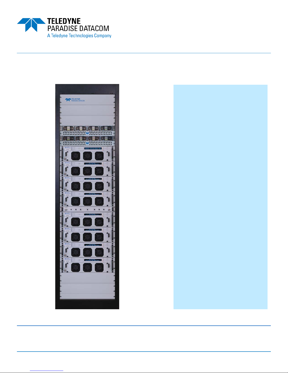
GaN PowerMAX
Second Generation GaN
Modular N+1 Phase Combined System
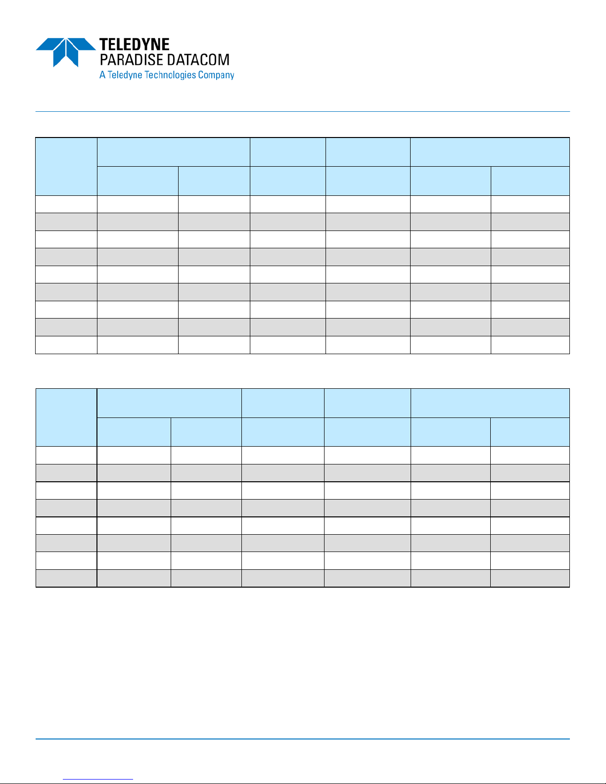
16 Module C-Band PowerMAX System Power Specifications
SSPA
Module
Power
Level
16 Module
RF Output Power AC Input
Power (W) 15 Module Redundant
RF Output Power
Psat, typical
dBm (W) PLinear, min.
dBm (W) Psat / PLinear Psat / PLinear Psat, typical
dBm (W) PLinear, min.
dBm (W)
50 W 58.0 (631) 55.0 (316) 8,000/6,400 20,000/15,000 57.2 (525) 54.2 (263)
100 W 61.0 (1259) 58.0 (631) 9,600/8,000 21,760/17,408 60.4 (1096) 57.4 (550)
150 W 62.8 (1905) 59.8 (955) 16,000/12,800 37,000/28,000 62.2 (1660) 59.2 (832)
200 W 64.0 (2512) 61.0 (1259) 17,600/14,080 39,189/29,614 63.4 (2188) 60.4 (1096)
300 W 65.8 (3802) 62.8 (1905) 24,000/20,800 52,000/43,400 65.2 (3311) 62.2 (1660)
400 W 67.0 (5012) 64.0 (2512) 28,800/25,600 61,000/52,300 66.4 (4365) 63.4 (2188)
650 W 69.1 (8128) 66.1 (4074) 52,800/44,800 115,517/93,757 68.5 (7079) 65.5 (3548)
800 W 70.0 (10000) 67.0 (5012) 64,000/56,000 139,511/117,751 69.4 (8710) 66.4 (4365)
Heat Load
(Btu/hr)
16 Module S-Band PowerMAX System Power Specifications
SSPA
Module
Power
Level
16 Module
RF Output Power AC Input
Power (W) 15 Module Redundant
RF Output Power
Psat, typical
dBm (W) PLinear, min.
dBm (W) Psat / PLinear Psat / PLinear Psat, typical
dBm (W) PLinear, min.
dBm (W)
50 W 57.5 (556) 54.5 (279) 6,400/4,800 14,960/11,800 56.9 (484) 53.9 (243)
100 W 60.0 (1000) 57.0 (500) 8,000/6,400 17,400/15,200 59.4 (861) 56.4 (432)
200 W 63.0 (2000) 60.0 (1000) 12,800/11,200 36,000/34,600 62.4 (1700) 59.4 (861)
300 W 64.8 (3000) 61.8 (1500) 20,800/16,000 43,433/36,949 64.2 (2600) 61.2 (1300)
400 W 66.0 (4000) 63.0 (2000) 25,600/20,800 52,300/47,900 65.4 (3400) 62.4 (1700)
500 W 67.0 (5000) 64.0 (2500) 28,800/24,000 56,500/54,000 66.4 (4300) 63.4 (2100)
600 W 68.0 (6300) 65.0 (3100) 35,200/27,200 68,285/60,254 67.4 (5400) 64.4 (2700)
800 W 69.0 (7800) 66.0 (4000) 40,000/32,000 74,200/69,750 68.4 (6800) 65.4 (3400)
Heat Load (Btu/
hr)
1000 W 70.0 (10000) 67.0 (5000) 64,000/56,000 130,000/129,000 69.4 (8600) 66.4 (4300)

PAGE 11 OF 16 214578 REV A ECO 18422
GaN PowerMAX
Second Generation GaN
Modular N+1 Phase Combined System
16 Module X-Band PowerMAX System Power Specifications
SSPA
Module
Power
Level
16 Module
RF Output Power AC Input
Power (W) 15 Module Redundant
RF Output Power
Psat, typical
dBm (W) PLinear, min.
dBm (W) Psat / PLinear Psat / PLinear Psat, typical
dBm (W) PLinear, min.
dBm (W)
300 W 65.6 (3631) 62.6 (1820) 24,000/20,800 52,137/43,433 65.0 (3162) 62.0 (1585)
400 W 66.9 (4898) 63.9 (2455) 32,000/27,200 69,714/56,658 66.3 (4266) 63.3 (2138)
650 W 69.0 (7643) 66.0 (3981) 52,800/44,800 115,517/93,757 68.4 (6918) 65.4 (3467)
800 W 70.0 (10000) 67.0 (5012) 64,000/56,000 139,511/117,751 69.3 (8511) 66.3 (4266)
Heat Load
(Btu/hr)
16 Module Ku-Band PowerMAX System Power Specifications
SSPA
Module
Power
Level
16 Module
RF Output Power AC Input
Power (W) 15 Module Redundant
RF Output Power
Psat, typical
dBm (W) PLinear, min.
dBm (W) Psat / PLinear Psat / PLinear Psat, typical
dBm (W) PLinear, min.
dBm (W)
50 W 57.6 (575) 54.6 (288) 9,600/8,000 24,000/19,600 57.0 (501) 54.0 (251)
80 W 59.6 (912) 56.6 (457) 11,680/9,360 28,313/22,000 59.0 (794) 56.0 (398)
100 W 60.6 (1148) 57.6 (575) 16,000/13,600 39,168/32,640 60.0 (1000) 57.0 (501)
150 W 62.4 (1738) 59.4 (871) 19,200/14,400 45,631/32,581 61.8 (1514) 58.8 (759)
200 W 63.6 (2291) 60.6 (1148) 36,800/32,000 91,413/75,000 63.0 (1995) 60.0 (1000)
300 W 65.4 (3467) 62.4 (1738) 44,000/33,600 106,500/78,500 64.8 (3020) 61.8 (1514)
400 W 66.6 (4571) 63.6 (2291) 51,200/38,400 122,000/87,000 66.0 (3981) 63.0 (1995)
500 W 67.6 (5754) 64.6 (2884) 64,000/48,000 152,300/108,750 67.0 (5012) 64.0 (2512)
Heat Load
(Btu/hr)

PAGE 12 OF 16 214578 REV A ECO 18422
GaN PowerMAX
Second Generation GaN
Modular N+1 Phase Combined System
General Electrical Specifications
PARAMETER NOTES LIMITS UNITS
Gain
Gain Flatness
Gain Slope
Gain Variation vs. Temperature
Gain Adjustment
Maximum, Ku-Band (Auto-Gain Off)
Maximum, Ku-Band (Auto-Gain On)
Maximum, S-, C-, X-Bands (Auto-Gain Off)
Maximum, S-, C-, X-Bands (Auto-Gain On)
full band
per 40 MHz
per 10 MHz (S-Band)
0 °C to +50 °C
0.1 dB resolution
62
57
70
65
± 1.0
± 0.3
± 0.3
± 1.0
20
dB
dB
dB
dB
dB
dB/40 MHz
dB/10 MHz
dB
dB
Intermodulation Distortion 3 dB back off relative to Psat -25 dBc
AM/PM Conversion (@ PLinear)
(@ PLinear)
3.5
1.0
°/dB
°/dB
Spurious
Harmonics
(@ PLinear)
(@ PLinear)
-65
-50
dBc
dBc
Input VSWR
Output VSWR
≤1.30 : 1
≤2.00 : 1
Noise Figure at maximum gain 12 dB
Group Delay Linear
Parabolic
Ripple
0.01
0.003
1.0
ns/MHz
ns/MHz2
ns p-p
Noise Output TX Band
RX Band (C-Band, without filter)
RX Band (X-Band, without filter)
RX Band (X-Band, with filter)
RX Band (Ku-Band, without filter)
RX Band (Ku-Band, with filter)
-75
-155
-85
-155
-85
-155
dBW/4 KHz
dBW/4 KHz
dBW/4 KHz
dBW/4 KHz
dBW/4 KHz
dBW/4 KHz
Residual AM Noise 0 - 10 KHz
10 KHz - 500 KHz
500 KHz - 1 MHz
-45
-20 (1.25 + log F)
-80
dBc
dBc
dBc
Residual Phase Noise Offset frequency from carrier
10 Hz
100 Hz
1 KHz
10 KHz
100 KHz
1 MHz
-90
-100
-110
-120
-125
-130
dBc/Hz
dBc/Hz
dBc/Hz
dBc/Hz
dBc/Hz
dBc/Hz
Environmental Specifications
Operating Temperature Ambient 0 to +50 °C
Relative Humidity non-condensing 95 %
Cooling System Integrated, forced air, per chassis 137 CFM
Audible Noise1per chassis, measured 1m from unit 71 dBA
1Audible noise is measured with the fans set at low. Add 3 dBA to the system audible noise figure (low fan) if using the cabinet exhaust option.
RF Leakage @ 1m, with SSPA module removed < 0.001 mW/cm2

PAGE 13 OF 16 214578 REV A ECO 18422
GaN PowerMAX
Second Generation GaN
Modular N+1 Phase Combined System
System Outline Drawing
The system pictured below is typical for an 8-Module C-Band system.
Note that certain power levels require a different power supply configuration. Consult with the factory
for details on your system’s prime power requirements.
23.31
[592.13]
76.25
[1936.75]
2RU FILLER
4RU FILLER
2RU FILLER
1RU PS2
1RU VENT
1RU PS1
1RU VENT
3RU SSPA 1
3RU SSPA 2
3RU SSPA 3
3RU SSPA 4
1RU RF DIST.
3RU SSPA 5
3RU SSPA 6
3RU SSPA 7
3RU SSPA 8
3RU FILLER
LEVELING
FEET (4X)
80.29
[2039.29] 77.63
[1971.68]
42.00
[1066.80]
38.25
[971.57]
13.97
[354.73]
1/4-20 UNC
CABINET
GROUND STUD
OPTIONAL
AC DISTRIBUTION
INPUT TERMINAL BOX
10x12x4 [254x304x101]
RF OUTPUT
CPRG137 WITH
THRU HOLES
OPTIONAL
16 PORT
ETHERNET
HUB
PASSIVE
POWER
COMBINER
PASSIVE
POWER
COMBINER
OPTIONAL 5RU
AC DIST. CIRCUIT
BREAKER PANEL
POWER
DISTRIBUTION
RAIL

PAGE 14 OF 16 214578 REV A ECO 18422
GaN PowerMAX
Second Generation GaN
Modular N+1 Phase Combined System
17.18
[436.4]
CABINET EXHAUST
OPTION
19.06
[484.0]
CABINET EXHAUST
OPTION
25.81
[655.6]
29.00
[736.6]
28.26
[717.7]
12 INCH EXHAUST DUCT
REMOVABLE
IMPELLER ASSY
12 INCH EXHAUST DUCT
LOWER EXHAUST IMPELLER
INCLUDED WITH 8-WAY SYSTEM
ONLY (OMIT FOR 4-WAY)
61.05
[1550.8]
59.18
[1503.2]
Cabinet Exhaust Option
The PowerMAX system is available with an optional cabinet exhaust
system, which includes a rear door for the cabinet and an impeller
assembly for each grouping of four (4) SSPA chassis in the system.
Power is provided from the AC Distribution Box to the circuit-interruptible
power connectors in the interior of the rear door. Separate power cables
connect from the outer door couplers to each impeller.
Outline Drawing, Cabinet Exhaust Option

PAGE 15 OF 16 214578 REV A ECO 18422
GaN PowerMAX
Second Generation GaN
Modular N+1 Phase Combined System
Spare Module/Chassis Part Number Configuration
Band
C-Band CC
X-Band XX
Ku-Band KU
S-Band SS
Module Configuration
M SSPA Module
C Single SSPA Chassis
Chassis Power Level (in Watts)
Band Output Power
S-Band 050, 100, 200, 300,
400, 500, 600, 800,
1000 (10K)
C-Band 050, 100, 200, 300,
400, 650 or 800
X-Band 300, 400, 650 or 800
Ku-Band 050, 080, 100, 150,
200, 300, 400 or 500
Use and Disclosure of Data
The items described herein are controlled by the U.S. Government and authorized for export only to the country of ultimate destination for use by the
ultimate consignee or end-user(s) herein identified. They may not be resold, transferred, or otherwise disposed of, to any other country or to any per-
son other than the authorized ultimate consignee or end-user(s), either in their original form or after being incorporated into other items, without first
obtaining approval from the U.S. government or as otherwise authorized by U.S. law and regulations.
Proprietary and Confidential
The information contained in this document is the sole property of Teledyne Paradise Datacom. Any reproduction in part or as a whole without the
written permission of Teledyne Paradise Datacom is prohibited.
Specifications are subject to change without notice.
TheSSPAModule(M)istheremovableassemblythat
isinsertedintoasystem’sexisngrackmountable
chassis.Thiscanbedonewithouttakingthesystem
off‐line.
TheSingleSSPAChassis(C)istherack‐mountable
chassis,withtheSSPAModuleassemblyinstalled.
Installinganewchassisrequiresasystemshut‐down.
GaN Designation
G GaN Technology
Frequency Sub Band
S-Band
2.02 to 2.12 GHz A
2.20 to 2.30 GHz B
C-Band
5.850 to 6.425 GHz A
5.850 to 6.725 GHz B
X-Band
7.900 to 8.400 GHz A
7.500 to 8.500 GHz B
14.00 to 14.50 GHz A
13.75 to 14.50 GHz B
Ku-Band
1.75 to 2.12 GHz G
H P A X X X X X G 2 2nd Generation

PAGE 16 OF 16 214578 REV A ECO 18422
GaN PowerMAX
Second Generation GaN
Modular N+1 Phase Combined System
System Part Number Configuration
H P A X G 2
Chassis Power Level (in Watts)
Band System Total Power, Psat
(# chassis) Single
Chassis
Power
(4) - “F” (8) - “E” (16) - “S”
C 178 W 316 W 631 W 050
C 355 W 676 W 1259 W 100
C 708 W 1413 W 2512 W 200
C 1000 W 1995 W 3802 W 300
C 1413 W 2692 W 5012 W 400
C 2291 W 4365 W 8128 W 650
C 2818 W 5370 W 10000 W 800
X 1047 W 1995 W 3631 W 300
X 1380 W 2630 W 4898 W 400
X 2239 W 4266 W 7643 W 650
X 2754 W 5248 W 10000 W 800
Ku 170 W 316 W 575 W 050
Ku 269 W 501 W 912 W 080
Ku 339 W 631 W 1148 W 100
Ku 513 W 955 W 1738 W 150
Ku 676 W 1259 W 2291 W 200
Ku 1023 W 1905 W 3467 W 300
Ku 1350 W 2512 W 4571 W 400
Ku 1698 W 3162 W 5754 W 500
C 537 W 1000 W 1905 W 150
S 180 W 316 W 556 W 050
S 320 W 562 W 1000 W 100
S 638 W 1100 W 2000 W 200
S 970 W 1700 W 3000 W 300
S 1280 W 2240 W 4000 W 400
S 1600 W 2800 W 5000 W 500
S 2000 W 3500 W 6300 W 600
S 2500 W 4500 W 7800 W 800
S 3200 W 5600 W 10000 W 10K Cabinet Option
Y With Cabinet
Z With Cabinet & Exhaust System
(1 exhaust impeller per 4 SSPA Chassis)
ENTER THE
SINGLE CHASSIS
POWER LEVEL
Band
C-Band CC
X-Band XX
Ku-Band KU
S-Band SS GaN Designation
G GaN Technology
Configuration Modifier 1
X Standard
Configuration Modifier 2
X Standard
R1RX Band Reject Filter
1X-Band and Ku-Band only
Configuration Modifier 3
X Standard
E Ethernet Switch
Module Configuration
E Eight (8) SSPA Chassis
S Sixteen (16) SSPA Chassis
F Four (4) SSPA Chassis
AC Distribution
X None
A Input Terminal Block; Circuit
Breaker Panel
2nd Generation
Frequency Sub Band
S-Band X-Band
2.02 to 2.12 GHz A 7.900 to 8.400 GHz A
2.20 to 2.30 GHz B 7.500 to 8.500 GHz B
1.75 to 2.12 GHz G
C-Band Ku-Band
5.850 to 6.425 GHz A 14.00 to 14.50 GHz A
5.850 to 6.725 GHz B 13.75 to 14.50 GHz B
Table of contents
Other Teledyne Amplifier manuals

Teledyne
Teledyne H-SERIES User manual

Teledyne
Teledyne 7 RU Chassis User manual

Teledyne
Teledyne PA-300 User manual

Teledyne
Teledyne SSPA User manual

Teledyne
Teledyne RCP2-1100 User manual

Teledyne
Teledyne DA1855A User manual

Teledyne
Teledyne PowerMAX User manual

Teledyne
Teledyne DA1855A User manual

Teledyne
Teledyne 6 RU Chassis User manual

Teledyne
Teledyne 7 RU Chassis User manual