Telegesis ETRX2DVKA-Plus User manual

Telegesis
TG-ETRX2DVKA-QS-02-302
ETRX2DVKA-Plus Development Kit
Dev Kit Quick Start Guide
3.02
ETRX2DVKA-Plus Development Kit
Quick Start Guide
Your ETRX2DVKA-Plus contains:
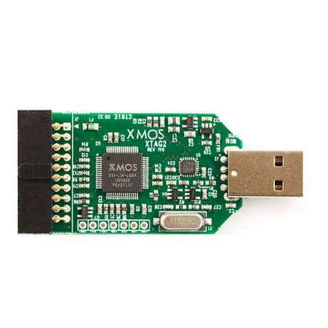
An ETRX2 USB stick
A Development Kit board
An ETRX2HW ZigBee module, to plug on to the Development Kit board
An ETRX2HRHW-PA module, to plug on to the Development Kit board
Two ETRX2MCB module carrier boards
One ETRX2MCB-PA module carrier board
Three battery holders for the module carrier boards
One USB cable
One half-wave antenna with adaptor cable
The ETRX2DVKA-Plus Development Kit has been designed to allow quick
evaluation and prototyping using the ETRX2 wireless mesh networking
modules. The Power Amplifier modules will allow you to test their greater
outdoor range and within-building penetration.

Before you start, go to our website software page at
www.telegesis.com/ZigBee/Dsoftware.htm and download the ETRX2USB
drivers and the Telegesis Terminal software. Install them on your computer.
Also, we recommend you to go to www.telegesis.com/ZigBee/Dmanuals.htm
and get the AT Command Manual, the User Guide, the Development Kit
Technical Manual and the USB Product Manual.
In addition, the Telegesis website has an introductory video -
How to set up and use your Development Kit.
See www.telegesis.com/support/suppt.htm
1 Connecting your Development Kit board
After you have installed the USB drivers, connect the Development Kit board to
the computer and load the drivers as prompted, then repeat for the USB stick.
Then right-click on “My Computer”, select “Manage” and “Device Manager”.
Under “Ports” you will see your Telegesis USB device(s); note the COM port
number that it is attached to (here, COM5). Now you can close the Device
Manager.
2 Application Software
If you do not wish to use the Telegesis Terminal Application program, the
command line of the ETRX2 can be accessed using any terminal software
program such as HyperTerminal®. Simply set up HyperTerminal® to connect
to the appropriate com port at 19200bps, Data bits - 8, Parity - none, Stop bits -
1, Flow Control –none (ETRX2 factory default).

However the Telegesis Terminal Application Software program allows
enhanced functionality especially suited to the ETRX2 modules. The AT-Style
commands can be issued by clicking on customisable „Command‟ buttons and
all of the 64 bit serial numbers which are reporting in are listed in a separate
window. This means you will not need to input any of the 64 bit serial numbers.
For instructions on how to use the AT-Commands read the AT Command
Manual and the ETRX2 wireless meshing module user guide.
After installing the Telegesis Terminal Application program the command
buttons for firmware R2xx based on EmberZnet2.x or R3xx based on
EmberZnet3.x will be shown at the bottom of the window. Use File -> Open
Layout to select the correct set of buttons. In order to use the Telegesis
Terminal software, select the correct COM port and the connection parameters
(ETRX2 default 19200, 8 bits, no parity, no flow control) and press the
“Connect” button. These settings are automatically retained each time the
software is re-started.
To get started quickly, power up one node connected to the PC and type AT
followed by <enter>. If the communication to the module is working the module
will prompt OK, if not check power and serial connections and make sure you
have connected to the correct COM port.
3 Network Set-up with Telegesis AT commands
To start a PAN network issue the AT+EN command, or alternatively press the
„Establish PAN‟ button. The local unit will now scan all available 16 channels
and establish a PAN with a random PAN ID on the quietest one. This may take
up to 16 seconds and leads to the node becoming the network‟s coordinator.
When successful the module will prompt „JPAN:cc,PPPP‟1, where cc is the
channel number and PPPP is the PAN ID of the newly created PAN.
If you get an error message instead it is likely that the module was already part
of a PAN, so you need to issue the AT+DASSL command or press the „Disas
Local‟ button to leave the PAN before going back to starting a new one. In
order to find the network status simply issue the AT+N command or press the
„NWK Info‟ button.
Once the network is established remote nodes can be powered up ready to join
in. If you have serial access to remote nodes simply issue the AT+JN
command or press the „Join any PAN‟ button to join the newly established
PAN. If you don‟t have serial access to the remote nodes (such as with the
three MCBs provided with the DVKA) you just need to wait for them to join the
network automatically.

By default all nodes (except coordinators) are set up to check once every
minute whether any neighbours on the same PAN are present, or whether they
are orphaned. If no neighbours have been found after a couple of minutes, the
unit will leave the (deserted) PAN and try to join into a new one once every
minute.
This initial network setup can take a few minutes, especially with no serial
access to remote nodes, but once the network is set up it will remain set even
after power cycles.
New nodes joining will cause a prompt „NEWNODE: <EUI64>‟1on the remote
side, where <EUI64> is the unique 64 bit identifier of the device joining in, and
display the JPAN message locally as described above.
To learn more about setting up and maintaining a PAN please refer to the User
Guide and the AT Command Dictionary.
4 Configuring Buttons for your set-up
After setting up the network, press the button labelled „Configure‟ which will
issue a command to scan the network causing all the nodes in the network to
report in. You will see that on discovery of a remote device its serial number is
added to the device list window. In addition to this, the configure functionality
will build additional buttons to allow toggling the LEDs („LED x ON‟ and „LED x
OFF‟) on a remote MCB as well as playing a tune on a remote devboard or
MCB („Ident Node x‟).
By looking at the actual commands behind these new buttons it is quite easy to
understand how the AT-Command interface operates. Also you can easily
discover the principle of mesh networking: simply move an MCB (or devboard)
out of range and then add an MCB or devboard between the local node and the
one which is out of range and you will find that the network has healed the
broken link and all three nodes are accessible again.
With a Development Board and a USB stick you can send messages between
two PCs using the Broadcast or Unicast buttons and by experimenting with
those buttons you will quickly get an understanding on how to integrate the
ETRX2 into your application.
The Telegesis Terminal Application also allows you to create custom command
buttons for your individual application, just click on Commands / Add
command button…
1R3xx firmware will also report Extended Pan ID and module‟s short address
Table of contents
Popular Computer Hardware manuals by other brands

Conrad
Conrad 97 19 46 operating instructions

Huananzhi
Huananzhi B760M-D4 user manual

Digital Equipment
Digital Equipment DECbridge 90FL owner's manual
Renesas
Renesas RL78 Series user manual
Alphacool
Alphacool Eisblock Aurora Acryl GPX-A Radeon RX 6800 Strix incl.... manual

MSI
MSI PCI-E 4.0 X16 RISER CABLE 180mm user guide
