teleorgin RB-MTX User manual

1

Index
1 Package..............................................................................................................................................5
1.1 Box..............................................................................................................................................5
1.2 Complete package contents........................................................................................................5
1.3 Modem version...........................................................................................................................6
2 General presentation..........................................................................................................................7
2.1 Front panel..................................................................................................................................7
2.2 Back panel...................................................................................................................................7
2.3 xternal connections...................................................................................................................8
2.3.1 Interfaces and connectors.....................................................................................................8
2.3.1.1 GSM antenna connector................................................................................................8
2.3.1.2 Modem serial port, either full RS232/RS485................................................................8
2.3.1.3 RJ-45 connector ............................................................................................................8
2.3.1.4 Power supply connector.................................................................................................9
2.3.1.5 Audio I/O.......................................................................................................................9
2.3.1.6 20-pin connector............................................................................................................9
2.3.2 SIM card holders................................................................................................................10
2.4 Product sticker..........................................................................................................................10
3 Basic features and services..............................................................................................................11
4 Using the modem.............................................................................................................................12
4.1 Setting up the modem...............................................................................................................12
4.1.1 Inserting SIM card(s).........................................................................................................12
4.1.2 Connecting antenna............................................................................................................12
4.1.3 Connecting power supply cable.........................................................................................14
4.1.4 Connecting UTP cable with RJ-45.....................................................................................14
4.2 Modem configuration...............................................................................................................15
4.2.1 Setting up the connection...................................................................................................15
4.2.2 Modem status page.............................................................................................................15
4.2.3 Local network.....................................................................................................................16
4.2.4 GSM network.....................................................................................................................19
4.2.5 Connection control.............................................................................................................20
4.2.6 Ports configuration.............................................................................................................21
4.2.7 TCP/IP forwarding.............................................................................................................22
4.2.8 VLAN.................................................................................................................................23
2

4.2.9 Static routes........................................................................................................................24
4.2.10 Dynamic DNS..................................................................................................................25
4.2.11 Access control..................................................................................................................26
4.2.12 Open VPN........................................................................................................................28
4.2.13 Ipsec static/Ipsec mobile..................................................................................................30
4.2.14 Generating SSL certificates..............................................................................................33
4.2.15 N2N..................................................................................................................................35
4.2.16 CARP...............................................................................................................................36
4.2.17 NTRIP configuration page...............................................................................................37
4.2.18 SMS Actions.....................................................................................................................38
4.2.19 GPIO................................................................................................................................39
4.2.20 CAN.................................................................................................................................41
4.2.21 Time..................................................................................................................................42
4.2.22 Syslog...............................................................................................................................43
4.2.23 User files..........................................................................................................................44
4.2.24 Backup and restore...........................................................................................................45
4.2.25 Discard changes...............................................................................................................45
4.2.26 Save settings ...................................................................................................................45
4.3 System logs description............................................................................................................46
4.4 Firmware update.......................................................................................................................48
4.5 lproma Device Manager.........................................................................................................49
5 Troubleshooting...............................................................................................................................51
5.1 No communication with the modem.........................................................................................51
5.2 Modem answers but there is no internet connection.................................................................51
6 Technical characteristics..................................................................................................................52
6.1 Mechanical characteristic.........................................................................................................52
6.2 Housing (dimension diagram)..................................................................................................52
6.3 lectrical characteristic.............................................................................................................53
6.3.1 Power supply......................................................................................................................53
6.3.2 RF characteristics...............................................................................................................53
6.3.2.1 Frequency ranges.........................................................................................................53
6.3.2.2 RF performance...........................................................................................................54
6.3.2.3 xternal antenna..........................................................................................................54
6.4 nvironmental characteristic....................................................................................................54
3

7 Terminal architecture.......................................................................................................................55
8 Safety recommendations.................................................................................................................56
8.1 General Safety...........................................................................................................................56
8.2 Care and Maintenance .............................................................................................................56
8.3 Responsibility ..........................................................................................................................56
9 Accessories......................................................................................................................................57
9.1 Accessories critical for using modem.......................................................................................57
9.2 Additional accessories...............................................................................................................57
9.2.1 Directional antennas ..........................................................................................................57
9.2.2 Omnidirectional antennas...................................................................................................60
9.2.3 Powr cable – open end......................................................................................................61
9.2.4 IO cable.............................................................................................................................61
9.2.5 RS232/486 cable...............................................................................................................62
9.2.6 DIN rail holder..................................................................................................................62
9.2.7 Bur holder..........................................................................................................................62
10 Conformity Assessment Issues......................................................................................................63
11 Safety Recommendations..............................................................................................................64
12 List of Acronyms...........................................................................................................................65
13 On-line support..............................................................................................................................67
4

1 Package
1.1 Box
Original box of the product is shown in the picture below.
We can find product sticker on the box. It matches modems sticker that is placed on the
device. This proves that your modem is original product. More information about stickers in
chapter Product sticker.
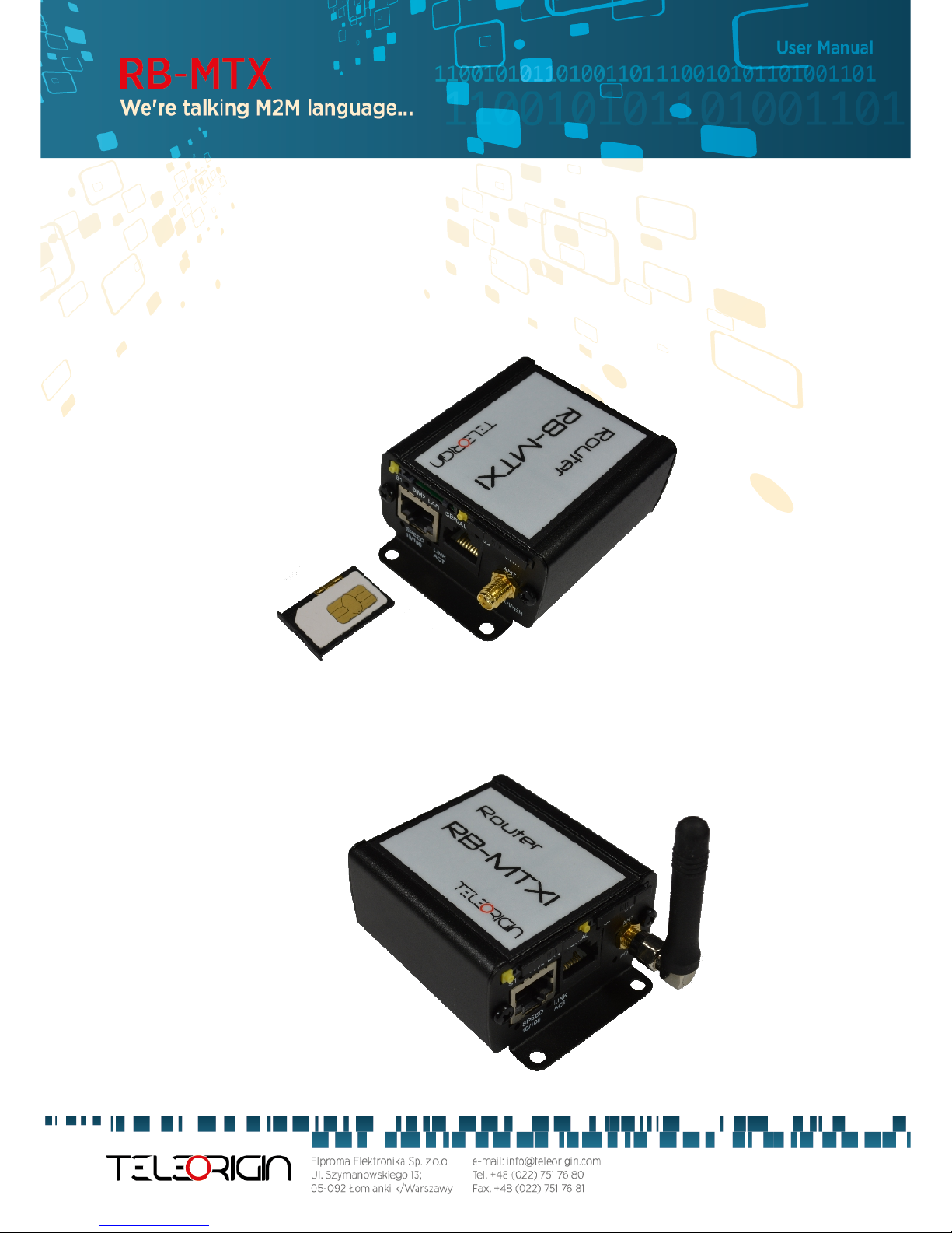
1.2 Complete package contents
omplete package contains:
A) RB-MTX modem
B) Antenna GSM (via SMA)
) Power supply adapter
5

1.3 Modem version
There are many ways to upgrade your RB-MTX modem. List below shows typical
configuration and different combinations (versions) of this terminal.
Option Typical Option
Power supply 6…30V 5V
PU LP 3130, ARM9 180MHz LP 3141, ARM9 270MHz
Memory
32MB RAM, 256MB MicroSD card
(part used for Linux system, the size of
SD card can be changed in the future)
NAND FLASH or DATAFLASH
RS232 Systems console (if AN, then RTS/ TS
unavailable) RS485
I/O connectors -
4 digital inputs, 4 digital outputs, AD
output, 2 analog inputs, I2, AN
interface, 3.3V output power supply,
audio I/O, miniUSB 2.0 (only without
WiFi modem)
onnection GPRS or EDGE UMTS or DMA
SIM Extractable Built-in
Dual SIM - Option unavailable in DMA version
Audio codec -
Mono microphone. Stereo input LINE IN,
Stereo output LINE OUT, or Speaker
output SPK OUT
LAN Ethernet 10/100Mbps WiFi modem (only without miniUSB)
Modem port configuration depends on central module used. Available modules with
described interfaces are shown in the table below.
G24 H24 DMA HE910
USB /dev/ttyA M0
/dev/ttyA M0
&
/dev/ttyUSB0
/dev/ttyUSB0
/dev/ttyA M0
&
/dev/ttyA M3
UART
/dev/ttyS1
Modem info or
Not refer
Modem info or
GPS Not refer Not refer
6

2 General presentation
2.1 Front panel
2.2 Back panel
7

2.3 External connections
2.3.1 Interfaces and connectors
2.3.1.1 G M antenna connector
SMA antenna connector placed on front panel is used to connect external GSM. To
establish connection with GSM network an external antenna must be used. Type of antenna
depends on GSM coverage. In good circumstances (level of received signal is high) use antenna
which is attached in the package. If range of GSM is low or none, an outdoor
directional/omnidirectional or indoor (for instance in place where GSM range is sufficient)
antenna should be used.
Note: If there is no antenna connected to SMA connector, the connection with GSM
network is impossible.
2.3.1.2 Modem serial port, either full R 232/R 485
Serial RS232/RS485 (through RJ-45 connector) is placed on front panel of modem and
it can be configured for special use as an option for customer.
R 485 line termination
In case a long RS485 line, the line should be terminated on both ends. It can
be realized by using an external terminator or by RT signals short-circuit (pins 1 and 3 of RJ45
connector for RS485 device option). The build-in terminator assumes 120Ω line impedance.
2.3.1.3 RJ-45 connector
RJ-45 connector is placed on front panel of RB-MTX modem and used for
communication with P or laptop to plug cable for Ethernet. In order to start configuration
pages of modem plug UTP cable between RJ-45 of modem and RJ-45 of your computer.
onfiguration pages are available in the web browser under IP address specified on the
modem (default address is 192.168.1.234).
8

2.3.1.4 Power supply connector
In the RB-MTX modem power supply 6V..30V care must be taken to ensure “clean”
power supply input and especially to avoid short transients on power supply lines originating
from inductive load switching. Otherwise internal module (G24, H24 or HE910) may be
permanently damaged.
2.3.1.5 Audio I/O
Audio Input and Output lines are available as option. There are three lines available:
SPK/LINE OUT – external speaker or line out
LINE IN
MI IN –microphone plug
2.3.1.6 20-pin connector
RB-MTX is available with 20pin connector as an option. Detailed description is shown
below.
PIN*
Upper row
F nction PIN*
Lower row
F nction
1 ADC IN1 2 ADC IN2
3 DAC OUT 4 NC
5 GND (not main supply input) 6 NC
7 IN1 8 IN2
9 IN3 10 IN4
11 OUT1 12 OUT2
13 OUT3 14 OUT4
15 I2C SDA 16 I2C SCL
17 CAN L 18 CAN H
19 GND (not main supply input) 20 +3.3V output, 75mA max.
GND – ground. Do not connect directly with minus of power supply input.
N – not connected
9

2.3.2 IM card holders
SIM card holders are placed in front panel of RB-MTX. To insert SIM card into the
extractable holder push yellow button and take holder out. Place SIM card as show in the
picture. To operate the module in a GSM network, it is necessary to insert at least one SIM card
obtained from the network operator.
2.4 Product sticker
A production sticker includes the following information:
●Product serial number
●the E marking
●the 15-digit bar code
●the model signature (RB-MTX)
Device sticker Box Sticker
10

3 Basic features and services
Basic features and available services are contained in table below.
Feature/service Description
tandard Supported bands:
Quad band 850/900/1800/1900/2100 MHz
800/1800/2600 MHz in LTE variant
E-GSM compliant
TX power:
850/900 MHz lass 4 (2W)
1800/1900 MHz lass 1 (1W)
LTE lass 3 (0.2W)
UMTS 2100 MHz lass 3 (0.25W)
EDGE 850/900 MHz lass E2 (0.5W)
EDGE 1800/1900 MHz lass E2 (0.4W)
Physical size:
Max. Dimensions: 83 x 60 x 34 mm (w/ connectors)
Enviromental temperature:
Min. 0° Max. 60°
Data features LTE (downlink 100 Mbit/s, uplink 50 Mbit/s)
HSPA+ (downlink 21 Mbit/s, uplink 5,76 Mbit/s)
UMTS (HSDPA 7,2 Mbit/s)
EDGE (Multi-slot class 10, max BR downlink 236,8 Kb/s)
GPRS (Multi-slot class 10, max BR downlink 85,6 Kb/s)
SD (Max BR 14,4 Kb/s)
Embedded protocols: T P/IP, UDP/IP, SSL, HTTP, HTTPS, FTP,
SMTP, POP3, IBM MQTT
lass B GSM 07.10 multiplexing protocol
Interfaces
(typical
version)
GSM antenna connector: SMA
2x SIM ard: 3V standard
RS232 or RS485 via RJ-45 (DB9 for special use*)
RJ-45 connector (x2)
power supply connector
Options* Dual SIM (not in DMA)
I/O interfaces ( AN, 3.3V output, miniUSB)
Audio I/O
*options, depending on clients needs
11
4 Using the modem
4.1 etting up the modem
To set the modem, do the following steps:
4.1.1 Inserting IM card(s)
Push yellow button place on front panel and take SIM holder drawer out.
Place SIM card(s) in the holder(s) as shown in the picture:
*modems are available with one or two SIM cards
4.1.2 Connecting antenna
onnect the GSM antenna to the SMA connector, or both GSM and GPS/ZigBee in optional versions of
the modem.
12

4.1.3 Connecting power supply cable
Connect power supply cable into power supply connector
4.1.4 Connecting UTP cable with RJ-45
Plug UTP or similar cable to RJ-45 plug.
13

4.2 Modem configuration
Modem is configured via web browser making it portable and easy to use. Modem
configuration is described below in following sections. Modem settings are divided into
sections which allows user to easily find option needed. When switching tabs settings are
automatically saved in modem cache, to save settings permanently and apply them click Save
Settings in menu. You can also discard changes by choosing appropriate option from the
bottom of the menu.
WARNING: ache is cleared on modem reset or pulling the power cable out.
WARNING: Not all tabs are available on every modem version.
4.2.1 etting up the connection
After you connect all necessary cables (see Setting up the modem Setting up the
modem) you can set up connection. onnect UTP cable to your computer and go to Internet
protocol T P/IP properties (Network connections -> Local Area Connection ->Internet
protocol TCP/IP-> Properties) and set your IP address as 192.168.1.x. Now modem will
connect your computer and its configuration page can be seen by going to default IP address
in your browser 192.168.1.234.
4.2.2 Modem status page
Go to your web browser and put IP address 192.168.1.234. You will be asked for
username and password. By default it is:
Username: admin
Password: 12345
If everything is configured correctly you should see following screen:
This is Status page of your modem. Here
you can see if modem is
connected/disconnected from net and its
parameters and parameters of PPP connection.
14

4.2.3 Local network
On LAN configuration page you can find essential parameters needed for LAN
connection. Here you can set IP Address (or set it to be downloaded via DH P), mask, default
gateway, DNS addresses. Last two options can be entered manually or downloaded
automatically via GSM or DH P. Modem can also work as DH P server-you can define its range
and set list of IP-MA binds.
15

4.2.4 G M network
On ISP Master page you can define internet connection parameters (APN, username,
password, SD, ISP IP and Modem band) for one or two SIM cards (depending on modem
version). To use internet you should know those parameters - they are essential for getting
access to internet. The parameters should be ensured by your mobile network provider. You
can find them by contacting your GSM network provider or visiting its website.
To enter the PIN for SIM card you need to mark “Enable” field and then fill the field
below with correct PIN. Outgoing calls are made always on MASTER SIM card.
16

4.2.5 Connection control
Here you can set parameters of switching between two SIM cards. You can define time
for ping and ping counter for 4 IP addresses you choose. In example (picture) here after 3
pings that take 10 seconds each card will change from Master to Slave or opposite.
17

4.2.6 Ports configuration
You are able to set port settings under RS232 Port page. There are 3 configurable ports:
/dev/ttyS0, /dev/ttyA M0 and /dev/ttyS1 or /dev/ttyUSB0 (depending on modem version).
Every port can be set to different mode. On /dev/ttyS0 you can set terminal, ModBus
gateway or NTRIP mode. Two other ports can work as modem port (modem control and
modem data) or SMS receiving port (see also: SMS Actions section).
Every port can also be set to forwarding mode that allows user to forward it to
T P/UDP port (as server or client). Port /dev/ttyS0 can also be forwarded to modem control
or modem data port-in that case no other mode can be set on that port.
Setting certain modes on /dev/ttyS0 and /dev/ttyS1 enables setting port parameters:
baud rate, data bits, parity checking and protocol. If parameter is inactive that means that user
can't control it in currently set mode.
4.2.7 TCP/IP forwarding
You can forward single port or port ranges onto certain IP address To add new rule for
single port, enter T P/IP Forwarding tab. In Single port rules section click button New and
enter all necessary information: identifier, check Enabled field, enter external and internal
18

port, choose protocol (T P or UDP) and enter IP address. When adding new rule or switching
tab, currently edited rule is automatically saved. You can delete it (or any other rule) by
pressing Delete button. After changes click Save Settings to save whole configuration. You can
edit port range rules in the same way in Port range rules section. You can also set IP address of
demilitarized zone in DMZ section.
4.2.8 VLAN
VLAN tab enables user to create virtual IP addresses. You can define IP, netmask and
identifier from range 0-4095. If you enable IEEE 802.1Q tagging Virtual IP becomes part of
19

VLAN.
4.2.9 tatic routes
Under static routes tab you can define your own routings. Please click Add new button
to add new routing. Enter identifier (used only to distinguish routings in www configuration),
choose interface, enter destination network, netmask and gateway.
20
Table of contents
Popular Network Router manuals by other brands


Alcatel
Alcatel SPEED TOUCH PRO user manual

H3C
H3C SR8800 IM-FW-II Command reference

ZyXEL Communications
ZyXEL Communications Prestige 652 user guide

D-Link
D-Link DES-2218 user guide

Tyco Electronics
Tyco Electronics 8 Port 10/100Mbit/s Ethernet Smart Switch with Fibre... Product user guide

NETGEAR
NETGEAR DG834v2 - ADSL Modem Router Specifications

TP-Link
TP-Link Deco X20-4g user guide

Linksys
Linksys BEFSX41 - Instant Broadband EtherFast Cable/DSL Firewall... Product data

EnGenius
EnGenius ECB9500 user manual

Nortel
Nortel Secure Router 2330 installation instructions

Avocent
Avocent DSR Series DSR1010 Quick installation guide

Robustel
Robustel GoRugged R2000 Installation and configuration quick guide