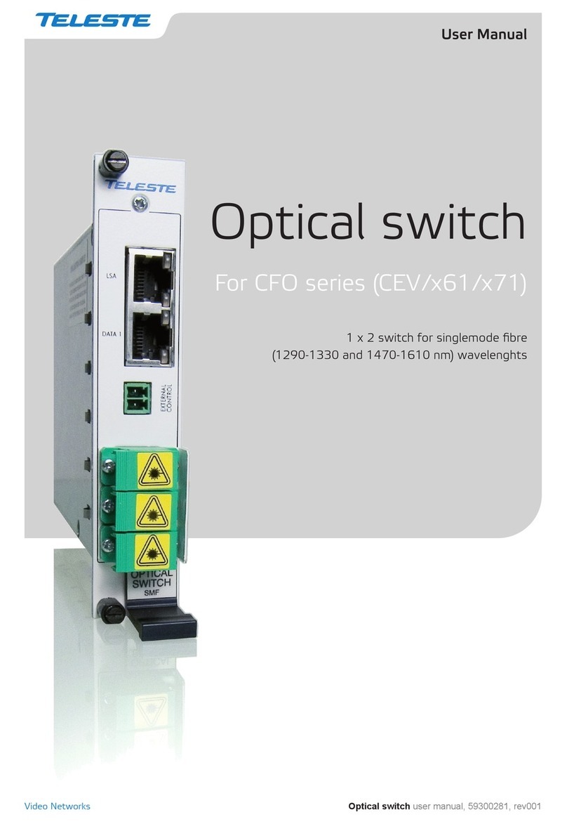
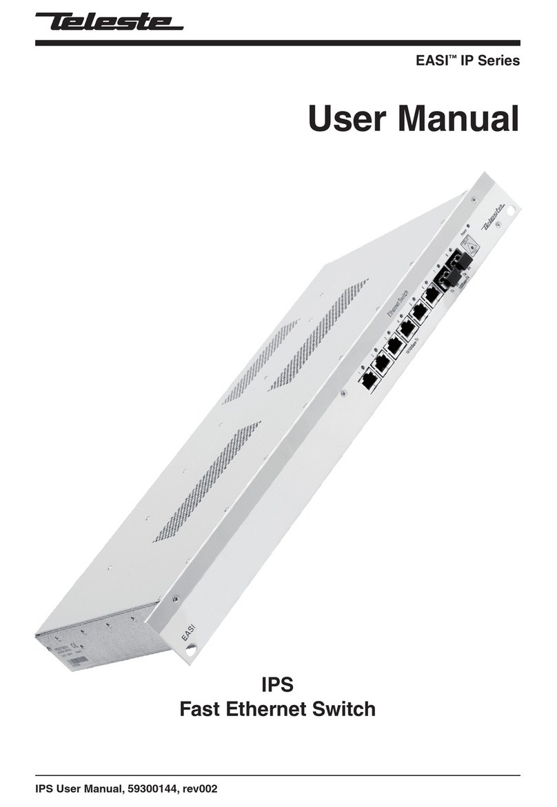
Teleste CFO OP-X series User manual

CFO OP-X Series
User Manual
CES User Manual, 59300180, rev002
CES
Unmanaged Fast Ethernet Switch

CES Series User Manual rev002
CES Fast Ethernet Switch Introduction......................................................................................................1
General ...................................................................................................................................................1
Switching Methods..................................................................................................................................1
CAT5 Cable Connection..........................................................................................................................2
Simple Network management Connection (SNMP)................................................................................2
Installation .....................................................................................................................................................3
Quick Instructions ...................................................................................................................................3
CES Front Panel ............................................................................................................................................4
CES Switch Mechanical Connections.....................................................................................................4
How to Unplug or Plug-in the SFP Transceiver Module..........................................................................5
Connections ..................................................................................................................................................6
Up-link Port Connections .......................................................................................................................6
Local Port Connections ..........................................................................................................................6
Management Connection .......................................................................................................................7
Fibre Connection ....................................................................................................................................7
IP Config Tool ...............................................................................................................................................8
Introduction .............................................................................................................................................8
System Requirements.............................................................................................................................8
How to Get the IP Config Tool.................................................................................................................8
How to Install the IP Config Tool.............................................................................................................8
Operating ................................................................................................................................................8
Device List Page....................................................................................................................................9
How to Configure the Switch...................................................................................................................9
Selected Device Page.........................................................................................................................10
Port Configuration Page.....................................................................................................................11
Notes on the IP Configuration Tool .......................................................................................................12
Trouble Shooting ...................................................................................................................................12
Firmware Upgrade via IP Config Tool ...................................................................................................12
IP Config Tool and Firmware Versions..................................................................................................12
Glossary................................................................................................................................................. 13-15
Technical Specifications ........................................................................................................................... 16
Copyright Acknowledgements ..................................................................................................................17
Contents

Welcome, and thank you for purchasing Teleste’s CFO OP-X Products.
General
CES is an unmanaged (supports limited management) field hardened
stand-alone Fast Ethernet Switch for video networking applications.
The CES supports SNMP management, port configuration, port alarms,
QoS (layer 2 and 3) and port mirroring.
Switching Methods
The Switch stores every incoming packet and scans this for errors,
usually by checking the frame CRC (cyclic redundancy check sum).
If any errors are found or detected the packet is discarded. In addi-
tion each frame is checked for size. Undersized packets (less than 64
Bytes) and oversized packets (more than 1518 bytes (*)) are also
discarded. Once these basic checks have been carried out the
Switch can then start learning packet source and destination informa-
tion. (*) When implementing Ethernet MAC tagging maximum Ether-
net packet length is increased to 1522 bytes.
The Switch needs to make a decision regarding which port(s)
the packet is to be forwarded to. This decision is based upon
the MAC tables that are maintained and updated automatically by
the Switch. The process is known as Layer 2 Switching. When first
powered on the MAC tables within the Switch are empty. When
a packet is received on a port the Switch does not know where
the destination MAC address is located. The Switch learns
the address by ‘flooding’ the packet out to all ports. Eventually,
the destination node responds, the address is located and the Switch
remembers the destination port. In simplistic terms; when a Switch
receives a packet on a port it stores the source MAC address in
the MAC table that corresponds to that Port. The flooding technique
is always used with Broadcast and Multicast packets. If the Switch is
equipped with multicast management then multicast packets will not
be flooded.
A MAC table can hold up to 2 K entries; and with a total packet
memory of 1 Mbit this is adequate for normal networks. Naturally,
devices will be disconnected from Ports during the life of a network.
If the MAC table did not automatically monitor for idle nodes the table
would become full. If a node has been idle for more than a few
seconds the source and destination information for that node will be
deleted from the table. This is commonly known as the ‘age time’.
MAC table size is normally always large enough for industrial net-
works. Packet memory size on the other hand can affect perform-
ance and ability to handle short high load/overload situations when
an event occurs in a control network or similar industrial network.
Stand-alone 8 port Fast Ethernet switch with 6 x 10/100Base-
Tx Local ports and 2 x 100Base-Fx Up-link ports, multimode or
singlemode devices
CES Fast Ethernet Switch Introduction
E
x6
M
gmt
CES Series User Manual rev002 1

CAT5 Cable Connection
All CAT5 ports support extended 150 m distances when using high
quality CAT5e or better cables. Both straight and cross connected
RJ-45 cables can be used for CAT5 connection. All CAT5 ports
support MDI/MDIX by automatically accepting both straight and
crossover Ethernet UTP cables. All CAT5 ports support also auto-
negotiation protocol, detects the various modes that exist in the
device on the other end of the wire and advertises it own abilities to
automatically configure the highest performance mode of interopera-
tion. The Switch also automatically corrects polarity errors. Further-
more the CAT5 UTP ports have isolation barriers between the signal
lines and the internal electronics withstanding 1500 Vrms (1 minute).
Simple Network Management Protocol (SNMP)
The CES switch supports SNMPv2c. SNMP enables network
administrators and control engineers to manage network perfor-
mance, find and solve network problems, and plan for network
growth. One feature of SNMP is that the SNMP agent (in this case
a CES switch) can send SNMP traps to one or more SNMP Hosts.
SNMP traps mean system alarms such as a port link loss or a port
enabled for port alarms or the switch temperature exceeding
a predefined threshold.
2 CES Series User Manual rev002

Quick instructions
Install the field hardened stand-alone CES device
(3U high, 10HP wide) to the CMA module adapter. A 12 V
supply voltage is provided by a CPS23x mains adapter.
Alternatively, install the rack mount CES device into a CSR-
installation frame equipped with a CPS power supply.
Switch on the power and see that all indicator LEDs on the
front panel are going thru a routine checking cycle.
Connect all necessary Ethernet cables.
Note! Management connection to the device can be created
via any of local port, although port 1 is the recommended.
Open IP Config tool on the computer connected to the
Switch and configure all necessary settings.
Make sure that the port indicator led on the front panel is lit
green on the ports where cables are connected. If the
indicator led is dark, the Ethernet connection does not
operate at that port.
Default network addresses for the devices are are
the following:
10.9.96.30 (IP address)
255.255.255.0 (Netmask address)
Installation
1
3
4
5
6
2
Picture 1. CPS23x series power supply with connector.
CES Series User Manual rev002 3

CES Switch Mechanical Connections
1. Locking screws (4 pcs).
2.
6 x Fast Ethernet (10/100Base-Tx) local ports (RJ-45 female)
and indicator leds
.
3. 2 x Fast (100Base) up-link ports. Up-link ports are equipped with
small form-factor pluggable (SFP) plug-in optical transceivers
(LC connector). If only one up-link port is required, the second
port can be left unused.
4. Handle
CES Front Panel
1
2
3
4
1
ETHERNET SWITCH
POWER
2
3
4
5
6
7
8
4 CES Series User Manual rev002

How to Unplug or Plug-in the SFP Transceiver Module
If your up-link port requirements change, simply unplug the existing
SFP module, and plug-in the new module. The SFP transceiver
modules must be installed before the switch is powered on. There is
no support for hot-swap. The SFP transceiver module has a bale-
clasp latch that makes easier to install or remove the module. Protect
the SFP module by inserting a clean dustplug into the module after
you remove the fiber cable. Be sure to clean the optic surfaces of
the fiber cable before you plug the cable into another module. Check
which connector plug is send (Tx) and which is receive (Rx).
hinge pin
latch
Bail clasp
Picture 2. SFP module’s locking release points.
To unplug and plug-in the SFP module, follow these steps
1. Open the bale clasp on the SFP module by pressing the clasp
downward until it is in a horizontal position.
2.
Use a small flat-blade screwdriver or
other long, narrow instrument
to push on the hinge pin to unlock the SFP cage latch.
3. Grasp the SFP module by the bale clasp and gently pull it out of
the
SFP cage
.
To plug-in the module:
4. Orient the transceiver with the bale clasp on the bottom, close
the bale clasp by pushing it up over the transceiver, then gently
insert the transceiver into the port until it clicks into place.
CES Series User Manual rev002 5

Connections
Picture 3. Ethernet connector (CAT5).
Table 1. Ethernet connector’s pinout
(CAT5 electrical).
Pin Signal
1 Tx +
2 Tx -
3 Rx +
4
5
6 Rx -
7
8
Table 3. Local port’s leds / indicator lights. * Port alarm can be enabled
from Selected Devide window, see page 14.
Picture 5. CES local and Up-link port connections.
Up-Link Port Connections (up to 2 pcs)
For Up-link network connections the switch has up to two (2)
100Base-FX Ethernet interfaces. The Ethernet connector is type LC
connector (see picture 4). See table 2 for explanation of up-link port
indicator led’s lights.
Table 2. Up-link port’s leds / indicator lights. Port alarm can be enabled
from Selected Devide window, see page 10. When an alarm is enabled and
the link is missing, this will be indicated by an orange light in the port led and
a red light in the Status led.
Local Port Connections (6 pcs)
A standard CES Switch comes with six (6) – 10/100Base-Tx local ports
(CAT5). All local port connectors are type of RJ-45 female (see picture 3
and table 1).
See table 3 for explanation of local port indicator led’s
lights.
All local ports support full wire speed. This equates to 100 Mbps
full duplex on every port. 100 Mbps in each direction on all ports equals
200 Mbps per port.
Led Colour Port mode
Led 2
Green
Connection to port is established
(left) Blinking green
Indicates the status of in/outgoing data stream
Dark Port is not in use
Led 1
Yellow
Link missing alarm (requires that port alarm is activated)
(right) Dark Port alarm is not activated
Led Colour Port mode
POWER
Green
Power ON
Blinking green
The switch is selected in the IP Config Tool
Red At least one port is generating a link missing alarm
(requires that port alarm is activated)
Port 8
Green
Connection to port is established
Blinking green
Indicates the status of in/outgoing data stream
Dark Port is not in use
Port 7 Green
Connection to port is established
Blinking green
Indicates the status of in/outgoing data stream
Dark Port is not in use
Local port 5
10/100Base-Tx
Up-link port 7
100Base-Fx
Up-link port 8
100Base-Fx
Local port 3
10/100Base-Tx
Local port 1
10/100Base-Tx
Local port 6
10/100Base-Tx
Local port 4
10/100Base-Tx
Local port 2
10/100Base-Tx
1
POWER
2
3
4
5
6
7
8
Picture 4a.
SFP plug-in optical
transceiver module.
Picture 4b. The optical connector
is the type of LC.
2 fibre version 1 fibre version
Tx Rx Tx/Rx
6 CES Series User Manual rev002

Management Connection
The CES Switch can be configured locally and/or remotely via any of
the Ethernet ports. However, port 1 is recommended for management
connection. The CES switches are configured with IP Config Tool
(see page 8).
Fibre Connection
Auto-MDIO is not supported on the fibre ports. Thus, the user must
make sure that the fiber drop link used is cross-connected. This is
easily verified by checking if the fiber port LED is on or not, when
the fiber drop link is connected between two switches or the switch
and a fiber enabled end node. Manual swooping of the TX/RX drop
link on one of the fiber devices is required in case the LED is off on
both devices. This can be done either directly on the switch fiber port
or on a fiber patch panel if this is available (preferably).
The optical Ethernet up-link interface is a small form-factor pluggable
(SFP, see picture 4). The small form-factor pluggable is a specifica-
tion for a new generation of optical modular transceivers. The optics
is not hot-swappable. The optical output level is constant and cannot
be adjusted.
When installing the fibre optic cable, do not exceed the minimum
bending radius when connecting cable to the system.
Note! For correct optical operation ensure that all optical connec-
tors are cleaned immediately before mating. Connectors should
always be cleaned using high purity alcohol (e.g. methyl or isopro-
pyl alcohol). Dry the surfaces using clean compressed air or other
equivalent pressurised gas. The optical connectors on the equip-
ment should always be protected with dustcaps when there is no
fibre inserted.
Optical Ethernet connection meets class 1 laser safety requirements
of IEC 825-2: 1993 and US department of health services 21 CFR
1040.10 and 1040.11 (1990) when operated within the specified
temperature, power supply and duty cycle ranges.
RADIATION
INVISIBLE LASER
CLASS 1
CES Series User Manual rev002 7

IP Config Tool
Introduction
This chapter introduces how the IP Config Tool is used to configure
and manage the CES switches. The IP Config Tool is used to config-
ure the network settings such as IP address, subnet mask and
default gateway of the CES switches. This Tool is also used to
configure the redundant ring and time server parameters.
Port 1 is always advised to be used as a local management port.
In case a device is connected to the Port 1, only remote management
is available.
System Requirements
• The CES Fast Ethernet switch (SW ver 2.06 or newer)
• The X86 based PC computer running Windows 2000 or XP
• Ethernet network card
• Administrative rights are required during installation
• The IP Config Tool (TelesteIPConfig.exe, ver 9.7.1 or newer).
• The interconnection Ethernet cable
How to Get the IP Config Tool
You can download the latest version of IP Config Tool from Teleste’s
web site at: www.teleste.com.
How to Install the IP Config Tool
Unzip the file IP_Config_Tool.zip by using e.g. WinZip and extract
all the files to the folder you want. Ensure that all files reside in the
same folder and that you can find the folder after you extract them
there. Start the program by running TelesteIPConfigxxx.exe.
Operating
The IP Config Tool consists principally of several windows. On the
Selected Device page you can configure the chosen device.
The IP Config Tool has the following configuration display pages that
are introduced in this document:
- IP Configuration / Device list
- Selected Device
- Port configuration
The information on configuration sheets is shown in data fields or
boxes. You can change settings in data fields or boxes whose back-
ground is white. Place your cursor in the desired data field or box and
enter the new setting. Some settings are entered by ticking a checkbox
or clicking on a radio button, by selecting from a pull-down list or by
scrolling digits with the help of spin buttons. Information without
datafield or box is read only parameter and can not be change.
8 CES Series User Manual rev002

Picture 7. Device list (with one Switch) page view.
How to configure the switch
1.
Connect the PC into the Ethernet port 1 of the CES switch via
Ethernet cable and open the IP configure tool by running the Teleste-
IPConfig.exe program. The following “IP configuration” window
appears on the screen (picture 6).
2. Assign a free IP address, which is in the same subnet as the PC, to
the “Default IP” and click Scan for button until the Switch appears
on the device list. Now all Switches in the same network will appear
on the device list (like e.g. in picture 7).
3. Click on the Switch that you want to configure --> “Selected Device”
window will appear on the screen (picture 8). From this window you
can modify the Switch settings.
Device list page
Picture 6. Empty device list page view.
Type L400 is managed and
L100 is unmanaged CES switch.
Press the “Scan for switches”
button to view all switches in the
same network.
CES Series User Manual rev002 9

Selected Device page
Picture 8. Selected device configuration page view.
Click on the Switch in the IP Configuration page window’s device list.
“Selected Device” configuration page will appear on the screen
(picture 8). On this page you can modify the Switch configuration:
IP address: Device IP address
Subnet mask: Mask for subnet definition
MAC address: Device MAC address
Host name: User definable alias name for the device
Location: User definable location name for the device
Enable port alarm: Enables port alarm
Port config: Opens port configuration window
To activate the settings restart the Switch at the Selected Device Page
by pressing RE button.
Press the “Get” button to view the
device’s current settings.
Press first the “Set” button and
then the “Restart” button to
activate the settings. Reboots the device
Press the “Save as” button to save
the current configuration to the disk.
Press the “Open” button to get any
saved configuration from the disk.
10 CES Series User Manual rev002

Port Configuration page
Picture 9. Selected device port configuration page view.
Click on the port button in the Selected Device page window
--> “Port configuration” window appears on the screen (picture
9). On this page you can modify the Switch’s port configuration:
Port: Port number
Link: Shows which link is operating
Auto-neg: Auto negotiation on/off
Half Duplex: Half duplex setting*
Full Duplex: Full duplex setting*
*Note! Forced selection when Auto-neg. is set off.
10 Mbps: Port speed setting
100 Mbps: Port speed setting
Scrambling: Allows the switch to code the traffic flowing through
the selected port. This setting is only available for the trunk ports
and must be the same on both sides of the link. This parameter
is important for backward compatibility: In older firmware ver-
sions (0.5x or 1.0x) scrambling is always enabled (and cannot
be changed)
Sniff port & Mirror port:
This feature allows to sniff the traffic
on a given port. The “Sniffed port” should be selected and all the
traffic will be redirected to the selected “Mirror port”
Press the “Get” button to view
the device’s current settings.
Press the ‘Set’ button after any
changes. Any changes will
have immediate effect (switch
restart is not required).
These settings will be selected
automatically when Auto-neg
is enabled.
Not In use
These settings are user-editable if the auto-
neg tick box for the port is not ticked.
Note! The auto-negotiation, duplex
connectivity and speed settings for an Fx
port are not user-editable.
The fiber configuration is not compatible with
older firmware releases of the switch
(versions before 2.06). The releases 2.06
and after can handle both scrambled and
non scrambled fiber communication. This
feature is configurable via IPConfig or SNMP.
CES Series User Manual rev002 11

Notes on the IP Config Tool
1. IP Config Tool’s subnet mask has to be same as PC’s.
2. IP Config Tool must have temporary IP address in the same subnet
as the PC (for example if PC has 10.9.96.5 the temporary IP can be
10.9.96.1).
Note! DO NOT USE SPACE BUTTON when typing default IP
address for IP Config Tool!
3. No reboot is required when changing IP and subnet mask settings.
4. If a switch is configured in the wrong way you may have to connect
the PC directly into this switch in order to correct the settings.
Trouble Shooting
1. In case Switches are not be found, check that there is no spaces
used in IP Config Tool’s default IP address field.
Firmware Upgrade via IP Config Tool
Upgrading an old switch firmware (like 0.50 – 1.06) to version 2.x
requires that version 1.08 is first installed.
1. Make sure that the PC, the IP Config Tool and the switches that are
to be upgraded are in the same IP subnet
2.
Unzip the zip file containing the new image to the FTP server directory
3.
Select the switch in the IP Config Tool that you want to upgrade
4.
Disable SNMP before upgrading the switch firmware
5. Write upgrade in “Host name” field and the name of the unzipped
filename (e.g. lx206.bin) in the “Location” field
6. Click “Set” button. A progress bar will appear in the bottom of the
dialog box, and the switches will restart (the upgrade time is less
than 2 minutes for the firmware versions 2.00 and newer)
Note! Make sure that you have waited at least 5 minutes after the
upgrade procedure is started (pushed the Set button) before you
remove power, or you have verified that the switch has restarted.
Removing power during the upgrade procedure might damage the file
system and the switch will not restart.
IP Config Tool and Switch Firmware Versions
The IP Config Tool version 9.7.1 or newer is recommended for switch
fi r m w a r e v e r s i o n 2.06. Switch control options for a switch will be enabled
based on the version of IP Config Tool and the firmware version running
on the switch. Older versions of the IP Config Tool can be used with the
latest firmware, but then the user might not be able to configure the new
switch features.
12 CES Series User Manual rev002

Glossary 13
Auto-Negotiation
A Protocol defined in the Ethernet standard that allows
devices at either end of a link segment to advertise
and negotiate modes of operation such as the speed
of the link, half- or full-duplex operation and full-duplex
flow control.
CSMA/CD (Carrier Sense Multiple Access /
Collision Detection)
A set of rules determining how network devices
respond when two devices attempt to use a data
channel simultaneously (called a collision). The
CSMA/CD method is internationally standardized in
IEEE 802.3 and ISO 8802.3.
DHCP (Dynamic Host Configuration Protocol)
Internet standard (RFC 1541) protocol for distributing
configuration information to network and allows a
computer to obtain its own IP address automatically
rather than having it entered manually.
Fast Ethernet (100Base-T and 100Base-X)
Uses CSMA/CD access method at 100 Mbps; IEEE
802.3u. Can use full duplex (200 Mbps).
Full Duplex
The ability to transmit and receive signals
simultaneously.
Gateway
Gateways are points of entrance to and exit from a
communications network. Viewed as a physical entity,
a gateway is that node that translates between two
otherwise incompatible networks or network segments.
Gigabit Ethernet (1000Base-T and 1000Base-X)
Informal name for standard IEEE 802.3z. CSMA/CD
technology designed to provide 1 Gbps network
connectivity. Based on existing and evolving 802.3
standards, Gigabit Ethernet is expected to incorporate
both half and full-duplex operation, link-level flow
control, VLAN support, and systems management.
Support for one repeater per collision domain, back-
ward compatibility with 10Base-T and 100Base-Tx.
Half Duplex
The ability to transmit and receive signals in both
directions, but only in one direction at a time.
Host
Any device on the network that implements communi-
cation above the Data Link Layer.
Hostname
A synonym for IP domain name, which typically takes
the form host.
Hub
A physical layer device, generally used to serve at
the center of a star-topology network. Hubs accept
Glossary
host, internetworking, and network management
modules; and provide re-timing/repeater, bridging,
and/or network management functionality. A hub is
an Ethernet multi-port repeater, which sometimes
referred to as a concentrator.
IEEE 802.3
Defines carrier sense multiple access with collision
detection (CSMA/CD) access method and physical
layer specifications.
IEEE 802.3u
Defines CSMA/CD access method and physical
layer specifications for 100BASE-TX Fast Ethernet.
IEEE 802.3ab
Defines CSMA/CD access method and physical layer
specifications for 1000BASE-T Gigabit Ethernet.
IEEE 802.3z
Defines CSMA/CD access method and physical
layer specifications for 1000BASE Gigabit Ethernet.
IEEE 802.1q
VLAN Tagging - Defines Ethernet frame tags which
carry VLAN information. It allows switches to assign
endstations to different virtual LANs, and defines a
standard way for VLANs to communicate across
switched networks.
IEEE 802.1d
Spanning Tree Protocol controls redundant links
between Layer 2 switches and ensures there’s only
one active path any two devices and no loops; does
not allow for load sharing, only redundancy.
IEEE 802.1p
Provides traffic class expediting and dynamic
multicast filtering. Essentially, it provides a mecha-
nism for implementing Quality of Service (QoS) at
the MAC level. 802.1p is part of the IEEE 802.1d
standard along with IEEE 802.1q.
IEEE 802.1w
Rapid Spanning Tree is an update of the original
Spanning Tree Protocol that improves Layer 2
convergence from 30 seconds or more to a few
seconds or less.
IEEE 802.3p
Provides QoS. Traffic is classified and prioritized
attending to Layer 2 class of service field.
IEEE 802.3x
Defines Ethernet frame start/stop requests and
timers used for flow control on full-duplex links.
IGMP (Internet Group Multicast Protocol)
The Internet standard (RFC 1112) extensions to IP
that support IP datagram multicasting to a “host

14 Glossary
group.” Membership in a host group is dynamic and
there are no topological restrictions to participating in
a host group. Hosts groups may be either permanent
or transient. Host groups are identified by Class D IP
addresses. There are three levels of conformance: 0:
no support; 1: support for sending but not receiving;
2: full support.
IGMP Querier
The device which manages IGMP service. IGMP
Querier asks all the devices in a network for possible
multicast groups of interest. In a IGMP enabled
network where multicast traffic is being delivered,
multicast receivers must join multicast groups,
advertise periodically their membership to the groups
and finally, leave the groups. There must be only one
IGMP Querier in a given network.
IP (Internet Protocol)
The most important protocol of the Internet suite. IP
allows information to traverse multiple networks
worldwide. The network layer protocol (RFCs 760, 791)
for the Internet protocol suite.
Local Area Network (LAN)
A local area network is generally a private network. It
is under the control of the owner and used by a set of
related individuals and/or workgroups, typically within
a single building or over a group of neighboring
buildings. LANs are a group of computers and associ-
ated devices that share a common communications
line and typically share the resources of a single
processor or server within a small geographic area
(for example, within an office building). A local area
network may serve as few as two or three users (for
example, in a home network) or many as thousands of
users (for example, in an FDDI network).
MAC (Media Access Control)
The protocol level that describes network management
frames sent on the 802.5 token ring. Most MAC frames
are handled transparently by the network adapter.
MAC Address
The unique physical (data link layer) address of an
individual network interface. The standard specifies
both 16- and 48-bit addresses. The 802.1 standards
committee has defined a canonical format for writing
and transmitting a MAC address. It is expressed as six
octets separated by hyphens, each octet represented
as twohexadecimal digits, least-significant bit first
(littleendian). (As a matter of custom, non-canonical,
most-significant bit first representation is given using
colons as the octet separator.) For example, 08-00-20-
85-e6-8d is a typical canonical MAC address. Within
the MAC address are a number of fields of interest.
The most significant (first) bit, known as the I/G bit (for
Individual or Group) is 0 if the address represents an
individual station; it is 1 if the address is a multicast
(group or broadcast) address. The second bit, known
as the U/L (for Universal or Local) bit is 0 if the ad-
dress is globally administered and registered with the
IEEE; it is 1 if it is a locally administered address.
MAC sublayer
Media Access Control sublayer. As defined by the
IEEE, the lower portion of the OSI reference model
data link layer. The MAC sublayer is concerned with
media access issues, such as whether token passing
or contention will be used.
Metropolitan Area Network (MAN)
A network that interconnects users with computer
resources in a geographic area or region larger than
that covered by even a large local area network
(LAN) but smaller than the area covered by a wide
area network (WAN). The term is applied to the
interconnection of networks in a city into a single
larger network (which may then also offer efficient
connection to a wide area network). It is also used to
mean the interconnection of several local area
networks by bridging them with backbone lines. The
latter usage is also sometimes referred to as a
campus network.
MIB (Management Information Base)
A collection of objects (database) that can be ac-
cessed via a network management protocol. See
SNMP and RFC 1066.
MIB-II (Management Information Base, Version 2)
The revised object definitions for Internet standard
network management. Objects are defined using a
subset of the Abstract Syntax Notation One (ASN.1).
See SNMP and RFC 1213.
Multicast
Communication between a single sender and multiple
receivers on a network. Streaming content can be
sent multicast from one server to many users.
Multicast Address
An address that refers to multiple network devices.
Synonymous with group address.
Netmask
A bit mask used to select bits from an Internet
address for subnet addressing. The mask is 32 bits
long and selects the network portion of the Internet
address and one or more bits of the local portion.
This is also sometimes referred to as the address
mask or subnet mask.
Network Address
The hostid 0 of an IP address is reserved; an IP
address with the hostid zero is used to refer to the
network itself.

Glossary 15
Network Layer: OSI Layer 3
Provides upper layers with independence from the
data transmission and switching technologies used to
connect systems; responsible for establishing,
maintaining, and terminating connections. Respon-
sible for routing, switching, and subnetwork access
across the entire OSI environment.
Ping (Packet InterNet Groper)
Ping is a program that “bounces” a request off of
another computer over a network to see if the remote
computer is still responding. If the ping comes back,
the remote computer is still alive.
QoS (Quality of Service)
Interactive video conferencing requires a high QoS.
QOS is important as it determines the quality of your
video call. Low quality of service results in latency and
a jerky picture with poor and inconsistent audio quality.
Ring
A network topology in which all nodes are connected
in a closed loop. Transmission is permitted by passing
a token around the ring; a node copies out messages
addressed to it and copies in messages addressed to
others. Message receipt verification can also be
performed with the token.
Router
On the Internet, a router is a device or, in some
cases, software in a computer, that determines the
next network point to which a packet should be
forwarded toward its destination. The router is
connected to at least two networks and decides which
way to send each information packet based on its
current understanding of the state of the networks it is
connected to. A router is located at any gateway
(where one network meets another), including each
Internet point-of-presence. A router is often included
as part of a network switch.
Server
A networked computer that contains public resources
or services that can be accessed using software
applications called “clients.”
SNMP (Simple Network Management Protocol)
A set of protocols for managing complex networks.
SNMP works by sending messages, called protocol
data units (PDUs), to different parts of a network.
SNMP-compliant devices, called agents, store data
about themselves in Management Information Bases
(MIBs) and return this data to the SNMP requesters.
SNMPv2 is
a proposed update of version 1, that
provides additional administrative structure, authen-
tication, and privacy.
Spanning Tree Protocol (STP)
A standard bridge protocol (IEEE 802.1d). This
protocol allows bridges to dynamically discover a
subset of the LAN topology that is loop-free and
provides connectivity to all LAN segments.
Switch
An internetworking device (multiport bridge) that
intelligently segments networks to increase overall
bandwidth, isolate traffic and provides an interface to
high-speed networks. The switch selects a path or
circuit for sending a unit of data to its next destina-
tion. A switch may also include some functions of the
router, a device or program that can determine the
route and specifically what adjacent network point
the data should be sent to. In general, a switch is a
simpler and faster mechanism than a router, which
requires knowledge about the network and how to
determine the route.
Type of Service (ToS)
A byte in the IPv4 header (RFC 1349). it is represented
in an 8-bit (1 byte) field in the header which is used by
a variety of QoS methods, including IP Precedence,
Differentiated Services Code Point, and ToS field.
Unicast
Communication between a single sender and a single
receiver on a network. Compare with Multicast.
VLAN (Virtual LAN)
Network configuration, emulating a broadcast do-
main, where stations communicate using LAN
protocols as if they were on the same LAN, but where
they are actually on multiple segments connected
through layers 1, 2, and/or 3.
Wide Area Network (WAN)
A geographically dispersed telecommunications
network. The term distinguishes a broader telecom-
munication structure from a local area network (LAN).
A wide area network connects local area networks to
one another, generally using public infrastructure or
services. The connections are made using the shared
public infrastructure, public infrastructure leased for
private use, and sometimes, private infrastructure
(e.g., fiber) with public services.

Technical Specifications
Parameter Specification Note
Optical
m/m 1310 nm 2 km 2 fibres
s/m 1310 nm 30 / 60 km 2 fibres
s/m 1550 nm 20 / 100 / 120 km 2 fibres
CWDM (ITU G.694.2) 100 km 2 fibres
s/m 1310/1550 nm 20 / 60 km 1 fibre
Ethernet
Local ports
Number of ports 6 full duplex
Standard 10/100Base-TX CAT-5 / CAT-5e
Up-link ports
Number of ports 1 or 2 full duplex
Standard 100Base-FX m/m & s/m fibre
Protocols
802.3 10Base-T
802.3u 100Base-TX, -FX
802.1p QoS layer 2
802.3p QoS layer 3 (IP ToS)
802.3x flow control
SNMP version 2c
DHCP IP address adquisition
FLHP proprietary protocol
Performance
Switching fabric Non-blocking layer 2
MAC address table size 2048 kB
QoS (Quality of Service) High-speed non blocking QoS switch fabric with
4 traffic classes. 1Mbit shared frame buffer
Parameter Specification Note
Management
IP config tool local via ethernet port
SNMP remote via network
General
Supply voltage 10.5...14 V DC
Power consumption 5 W no fiber version
5,7 W one FX transceiver
6,4 W two FX transceivers
Dimensions (H x W x D) 3U • 10HP • 190 mm
Weight 0.7 kg
Connectors RJ-45 CAT-5 (UTP)
LC optical m/m & s/m
Operating temperature -34...+74 °C field-hardened
Storage temperature -40...+80 °C
Humidity 95 % non condensing
Emissions EN61000-6-3
Susceptibility EN50130-4
Switching Fabric
CES Fast Ethernet Switch
6 x
10/100Base-TX Ports 2 x
100Base-FX Ports
Fast Ethernet
Network
Traffic
System
Controller
IP
Camera Weather
Station
PCVoIP Etc.
Local
Port 1
Local
Port 2
Local
Port 3
Local
Port 5
Local
Port 6
Uplink
Port 1
Uplink
Port 2
Local
Port 4
16 CES Series User Manual rev002

Copyright acknowledgements
Information in this document is subject to change without notice and does not
represent a commitment on the part of Teleste Corporation.
Copyright © Teleste Corporation. All Rights Reserved.
No part of this document may be reproduced, transmitted, stored in a retrieval
system, or translated into any other language without the express permission
of Teleste Corporation.
Teleste Corporation
Video Networks
P.O. Box 323
FIN-20101 Turku
FINLAND
www.teleste.com
WEEE directive
Directive 2002/96/EC of the European Parliament and of the Council on waste
electrical and electronic equipment (WEEE) obliges that producers appropriately
mark electrical and electronic equipment with the symbol indicating separate
collection. This obligation applies to the equipment put on the market in EU after
13 August 2005.
Teleste devices which belong to the scope of the directive have been marked with
the separate collection symbol shown below. The marking is according to the
standard EN 50419. The symbol indicates that the device has to be collected and
treated separately from unsorted municipal waste.
User manual revision history note:
The latest version is always available in pdf-format on our web site:
www.teleste.com
CES Series User Manual rev002 17

www.teleste.com
Other manuals for CFO OP-X series
1
Table of contents
Other Teleste Network Router manuals
