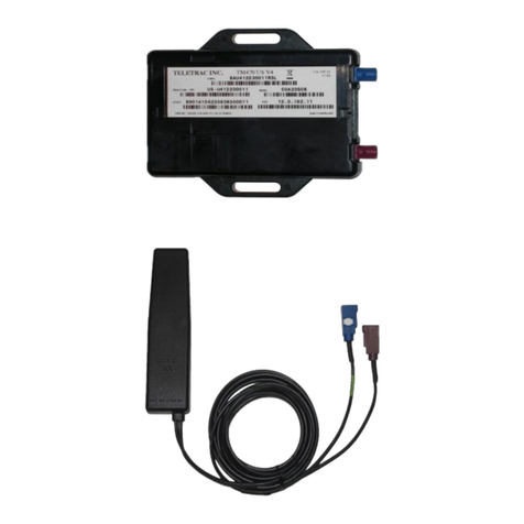
Teletrac Color Touch Screen User manual

Color Touch Screen Installation Guide
for the Prism TM2 and TM2J Units
Document Number: 1557-0300 00
Date: June 29, 2009

TableofContents
Overview...............................................................................................................1
KitComponents.....................................................................................................1
Pre‐InstallationVehicleInspection.......................................................................1
PreparationInstallationForm...............................................................................1
InstallationInstructions........................................................................................2
CableandFunction...............................................................................................3
WiringforaCTO....................................................................................................3
SuitableLocationsforPrismMounting................................................................4
SuitableLocationsfortheCTO.............................................................................5
CTOMount............................................................................................................5
SteelBracket...................................................................................................5
InstallingthebrackettotheCTO....................................................................6
MountingBracketOptions.............................................................................6
ProtectingtheSDCardSlot...................................................................................7

ColorTouchScreenInstallationGuide
Teletrac, Inc 1557-0300 00 Page 1
OVERVIEW
ThepurposeofthisdocumentistoprovidetheVSRswithinstructionsonhowtoinstallthe
ColorTouchScreen(CTO)devicewithboththePrismTM2andPrismTM2Jhardware.
KITCOMPONENTS
ThefollowingisalistofcomponentsnecessaryfortheinstallationoftheCTO.
•PrismUnit
oTM2with2.0.130.12firmware
OR
oTM2Junitwithxxxxxfirmware(attimeofpublicationaproductionfirmware
buildhasnotbeencompiled.
•Comboantenna
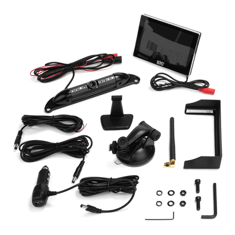
•CTOandmountinghardware
•CTOcable
•MainPowercableforTM2/TM2J
•GPSAntenna–through‐holeormagneticmountoracomboglassmountantenna
•Wiringharness–StandardTM2/TM2Jharnesswith8‐pinconnectororVLUtoPrism
adapter
PRE‐INSTALLATIONVEHICLEINSPECTION
Ensurethatallmajorelectricalandmechanicalcomponentsareinworkingorder.Thiswill
include:
•Headlamps
•Airconditioner
•Domelights
•Turnsignals
•Radio
•Windshieldwipers
•Startvehicleengineifpossible
•Identifywarninglightsonthedash
PREPARATIONINSTALLATIONFORM
Priortoinstallationthefollowinginformationmustbecompleted:
•Recordtheunit’sIPandvehicleIDontotheinstallationform.
•Affixthepre‐printedlabelontotheinstallationform.
Aftertheinstallationiscompleteacopyoftheinstallationformisgiventothecustomer.
TheothercopymustbereturnedtoTeletracCustomerCareCentertobeplacedinthe
customer’sfolder.

ColorTouchScreenInstallationGuide
Teletrac, Inc 1557-0300 00 Page 2
INSTALLATIONINSTRUCTIONS
AllVSRswillreceiveaCTOprogrammingkitthatincludesthefollowing;
•InstallationInstructions
•SDCardreaderforUSBconnection
•Onepackageof20SDSlotLabels
Note:Duetotheimportanceoftheconnections,itisMANDATORYthatallconnections
mustbeeitherSOLDEREDorCRIMPEDwiththepropercrimpingtool.UnderNO
circumstancesshouldtape,Scotch‐Loc,orT‐Tapconnectionsbeusedforwrapping.TheCTO
feedsfromtheIgnitionOn‐Lineforpower;therefore,itisimportanttohaveasolidsourceof
ignition.Withoutasufficient“IgnitionOn‐Line”power,theCTOdevicemaybehave
erratically.
LocatesuitablelocationsforthePrismTM2/TM2JandGPS/GPRScomboantenna.
1. ConnecttheantennasandroutethecabletotheTM2/TM2J’slocation.Placeitat
leastfourfeetawayfromanyotherantennas.
oNote:Ifplacingonthebottom,thecablemustalwaysberoutedawayfrom
theantennaandthecableshouldNEVERberoutedALONGit.
2. IfaWEDGEantennaisused,besuretoplaceitonthepassengersideofthe
windshield.
3. IfaRoofMountedantennaisused,theinstallationrequiresaholebedrilledonthe
vehicle.
oNote:
Theexactsizeonthedrilledholeis7/8inchindiameter.
Thecoaxmustberunbehindthepanels.
AvoidanyblockageoroverheadracksthatmayhinderGPSsignal.
Besurenottodrillintoadoublemetalsegmentoftheroof.
Applyalayerofsiliconearoundbothoftheantennabases.
Applytamper‐proofingtoallconnectors(nailpolish,paint,etc.)
4. ConnectthePrismTM1/TM2wiringharnessasrecommendedbelow.
oForSafetypurpose:
Removethefusefromthefuseboxuntilinstallationiscomplete.
Nevertapintoexistingpowerorignitionwiresusebyother
aftermarketdevices.
oGround–LocatechassisgroundwithinonefootoftheTM2placement.
Ifthechassishassoundabsorbentmaterials,besuretoscrapeoffthe
materials.
Alwaysuseastarwasherwhenattachingtochassisground.
oRunConstant+12VoltWire–Attachoneendofthefuseholderto
determinethepowersource.
Recommendtohavethestartersolenoid(main+12volt)terminal
placebehindthefuseboxorbatterydistributionblockoftheend
compartmentbehinddash.

ColorTouchScreenInstallationGuide
Teletrac, Inc 1557-0300 00 Page 3
DONOTusetheexistingfactorywiresattachedforgrounding.This
maycauseinterference.
oRunIgnitionWire‐Attachoneendofthefuseholdertodeterminea+12volt
(usingaMulti‐meter)ignitionswitchsourcethatwillbesetasground.
Recommendtohaveitplacesbehindtheignitioncylinder,fuseboxor
thestartersolenoidintheenginecompartment.
**TIP:UseavoltmetertomakesurethevoltageoftheattachedlineDOESNOTget
droppedtozerowhiletheengineisstarting(Cranking).Thislinewillbereferredas
the“TrueIgnition”.
5. MounttheTM2/TM2Jtovehicle’schassiswithmountingbracket.
6. Securetheunitwithfourscrewsorfourcableties.
7. Zip‐tieanyexcesswireslackaroundthefuseholdertopreventtampering.
8. AttachPrismwiringharnesstothePrismTM2/TM2J.
9. Verifyallwiresaresolderedorcrimped.
10. ConnecttheGPRSandGPSconnectorstothePrismTM2/TM2J.
11. Attachthemainpowerandinsertthefuseyouremovedinstep#5.
12. ConfirmtheunitreceivesGPSandGPRSsignals.
13. TurnthevehiclekeytotheONpositionandverifytheCTOisactive.
14. ProperlysecuretheCTObyusingthesupplieddouble‐sidetape.
15. Securethebracketwithscrews.
*Besuretohavecustomerapprovalbeforesecuringthebracketwithscrews.
CABLEANDFUNCTION
ItisimportanttodetermineiftheCTOwillbe“MessagingEnabled”.IftheCTOwillbeused
asamessagedisplayterminal(MDT)youmustusethecorrectcable.Themessagingcable
willbetaggedindicatingitis“messageready”.Ifmessagingwillnotbeused,pleaseusethe
cablewithoutatag.
WIRINGFORACTO
BecausetheCTOhasitsownpowerconnectorinordertofacilitateitswiring,thefollowingstepsare
tobefollowed;
1) InstalltheTM2/TM2Jasnormal,ensuringthatalltherulesarefollowedandmake
surethattheTM2/TM2Jcomesonanditregisterswiththenetwork.
2) Disconnectthe6pinpowerplugfromtheTM2/TM2Jandconnectitintothe3pin
femaleplugcomingfromtheCTOpigtailloom.Makesurethatthelockofthe6pin
powerMolexlocksontothetabofthe3socket.
3) Connectthe6pinsideofthepigtailfromtheCTOintotheTM2/TM2J.Seethe
followingpictures.

ColorTouchScreenInstallationGuide
Teletrac, Inc 1557-0300 00 Page 4
4) ConfirmtheCTOconfiguration.IttheCTOwilldomessagingtheGREENCableon
PLUG3mustbeconnectedtotheREDwire.IftheCTOwillnotdomessaging,then
theGreenwiremustbeconnectedtotheBLUEwire.
5) Basedonpicturebelow,performthefollowingsteps:
a)RemovePlug1fromtheTM2/TM2J.
b)ConnectPlug1intoPlug2.
c)ConnectPlug3intotheTM2/TM2J.ThiswillensurethattheCTOwillreceive
Power/Groundandcontrolsignal.Note;theexistingDB9willnolongerbeusable,if
youneedtoperformdiagnosticsorrepairssimplyreconnectPlug1intothe
TM2/TM2J.
Thepowerconnector(6‐Pin)isthesameforboththeTM2andTM2J.Thesame
connectionprocedurewillapply.
ConnectionDetail
SUITABLELOCATIONSFORPRISMMOUNTING
Note:ThePrismwillNOTbeplacedonthedriversidearea.Usethesystemlayoutas
referencetowherethewiringharnessesroutingandconnectionpoints.Avoidplaceswith
extremevibration,heat,moistureanddust.Allinstalledequipmentswillbeconcealed.
•Aflatsurface.
•Underdashboard(AlwaysonthePassengerside).

ColorTouchScreenInstallationGuide
Teletrac, Inc 1557-0300 00 Page 5
•Invehicletrunkwhereluggageandotheritemswillnotcomeintocontactwiththe
unit.
•Behindpassengerseat.
•Theconsoleorbehindtheglovecompartment.
•Insidetheoverheadconsole.
•Thecoaxfortheantennasmustberunbehindthepanelsandinpillars.
•ObtaincustomerapprovalfortheMDTandantennasmountedlocations.
SUITABLELOCATIONSFORTHECTO
ThesamerulesandprecautionsthatapplyfortheinstallationofMDTswillapplyforthe
CTO.
•PlacetheCTOwithineasyreachofthedriver.
•Avoidthetopofthedashboard.Itisillegalinsomestatesandifanyholesaredrilled
theycannotbeeasilyrepaired.
•Avoidangleswheretoomuchglarewillbeaproblem.
CTOMOUNT
WhenattachingtheCTOutilizingthestandard“AdhesiveLargeFlangeMount”itis
importantthatthesurfacebefreeofdust,greaseoranyothercontaminantthatwill
impedetheproperbondofthetapetothedashboardorglass.
STEELBRACKET
Ifutilizingthesteelbracket(screwontype),itisdesignedtobeadheredtothevehicleusing
thesupplieddoublesidedtapeorsimplybyrunningtwoscrewsthruthesuppliedholes.If

ColorTouchScreenInstallationGuide
Teletrac, Inc 1557-0300 00 Page 6
usingscrewsbesuretoobtaincustomerauthorizationpriortodrillingintoadashboard.
MDTinstallationrulesapply.
INSTALLINGTHEBRACKETTOTHECTO
RemovethebottomscrewsoftheCTOmounttogainaccesstothesilverPhillipsscrew
insidethemount.RemoveandreplaceitwiththeSteelBracketutilizingthelongscrew‐
provided‐.SecurethescrewandaligntheCTOmount.
MOUNTINGBRACKETOPTIONS
AnoptionalSuctionCupTypeMountforglasssurfacesisavailablebyspecialorder.
PartNumber:331‐0124

ColorTouchScreenInstallationGuide
Teletrac, Inc 1557-0300 00 Page 7
PROTECTINGTHESDCARDSLOT
AlwaysusetheSDCardSlottapetoprotecttheSDcardfrommoisture,dirtandtampering.
IfreprogrammingtheSDcardbesuretoplaceanewstickerbeforeleavingthevehicle.The
stickersareavailablethroughDistributionanddonothaveapartnumber.Simplyorderthe
labelsaspartofthevanstockorder.
TheCTOwillalreadyarrivewithaprogrammedSDcard.IfyouneedtoreprogramtheSD
card,pleaserefertodocument1554‐050400‐CTOw/MessagingSoftwareUpdate
Instruction.
Table of contents
Other Teletrac Automobile Accessories manuals
