Teletrac TM470J User manual

Cassens Transport Company
Installation Specification Guide
Rev 1.1 11/14/2012
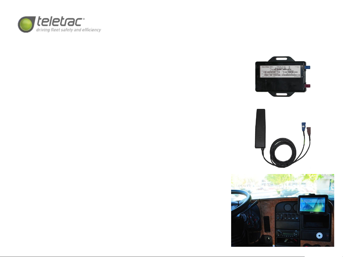
Equipment Overview
Cassens will be utilizing the following
equipment package:
•TM470J with diagnostics
•CTO7
•PTO
•HOS (FIL)
•Standard wedge antenna
All installations must be completed as
set forth in this installation specification
guide. Any deviation requires approval
from the National Vehicle Support
Manager or from the Director of Field
Service.

General Installation Requirements
•All power connections must be either soldered or made using the poke and wrap
(aka “lineman’s ties”) method. Wrap and tape, T-taps, Scotchlocks, or any other
power connection method is unacceptable.
•All cabling must be neatly routed and run, using zip-ties to secure the wiring.
•All connections made in the vehicle and all connections on the TM470J must be
tamper-sealed using the provided Torque Seal.
•The TM470J must be securely mounted , with screws being the preference, but
wire-ties being an acceptable alternative, if necessary.
•The removable sticker from the TM470 must be affixed to the doorjamb of the
passenger’s side of the vehicle.
•Prior to contacting Verification, use the diagnostics app on the CTO7 to verify the
IP, the GPS signal, the wireless signal, the PTO status (on/off), and the ignition
status (on/off).
•When installing a PTO sense, the default is the grey negative input. If a vehicle
has a positive PTO output, please follow the diagram on the next page that
details the use of a relay to invert polarity.
•Upon the completion of the installation, the technician must call for verification
at 714.934.8770. The verification code provided at the end of the call must be
notated, as it is a requirement for payment.

Using a Relay to Invert Polarity for PTO
Negative Input for Positive PTO
Relay Pin Description
87 Ground
87a Not Used
86 Ground
85 PTO (Positive output)
30 Prism (Gray Wire TM2 & TM450, Orange on TM2J)
Using the above table, wire the relay in-line, ensuring that all
connections are soldered or butt-connected and taped. Cut the
87a wire short and ensure that the blank end is securely taped.
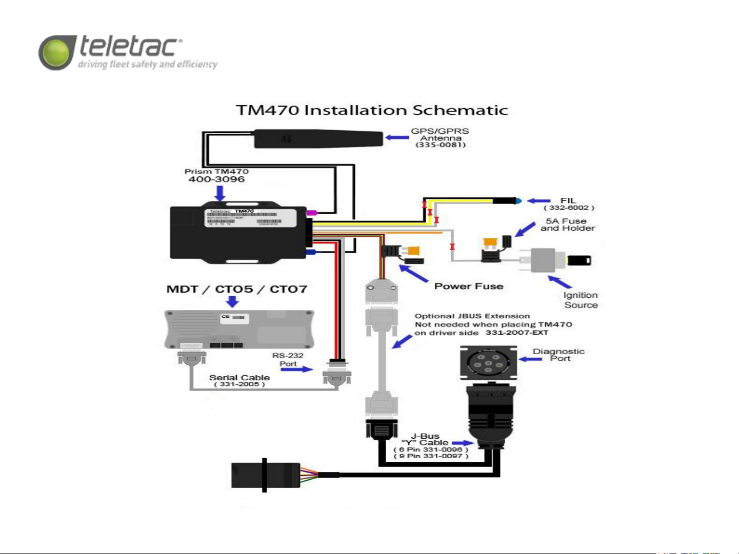
TM470J Installation Schematic

TM470J Cabling Pinout
Pin #
MicroPlug
Function Color
1Diag RX NA
2Input Positive Orange
3Ground (GND) Black
4Input Negative Gray
5Relay driver output (RELAY2) Blue
6TBD NA
7Relay driver output (RELAY1) –FIL- Yellow
8SAE J1708 bus A signal (J1708A) Yellow (twisted with Blue)
9CAN bus L signal (CANL) Brown (twisted with Red)
10 Diag TX NA
11 Info switch input (ISW) NA
12 Ignition Sense (IGN) White (twist 3/5/12)
13 DB9 RS232 Yellow
14 DB9 RS232 White
15 Ground (GND) Black
16 Battery supply rail (VBATT) Red
17 SAE J1708 bus B signal (J1708B) Blue (twisted with Yellow)
18 CAN bus H signal (CANH) Red (twisted with Brown)
CTO7 Installation Requirements
This is only an overview of the
CTO7 installation procedure. Please
refer to the “CTO7 Kit Instructions”
document for a greater level of
detail.
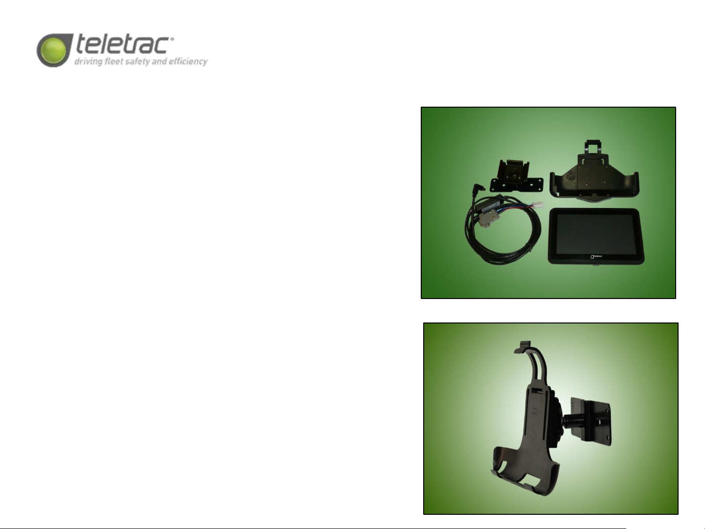
The CTO7 full kit is shown at top
right. The assembled standard
mounting bracket is shown at
bottom right.
The CTO7 installation must be
completed as set forth in this
installation specification guide. Any
deviation requires approval from
the National Vehicle Support
Manager or from the Director of
Field Service.

CTO7 Installation Requirements, con’t
CTO7 Testing: Prior to calling for verification, please ensure that the following testing
procedures have been completed on the CTO7:
•Log into HOS using “test” as the username and “1234” as the password. Ensure that
HOS field at bottom of screen changes from off duty to on duty. After 3-5 minutes, log
out and ensure that duty status changes to off. There is no need to sign the logs.
•In the navigation screen, input a route to ensure that the CTO7 can navigate to an
address.
•Send and receive a message from the messaging screen. This test will be repeated
during the verification call.
NOTES: Be sure to use the CTO7 MARKED CABLE. Using the CTO2 cable will damage the
cable and the CTO7 may not work properly.
Ensure that CTO7 snaps securely into the mounting bracket, and that the mounting
bracket and articulation is tight and secure.

Sterling LT Series

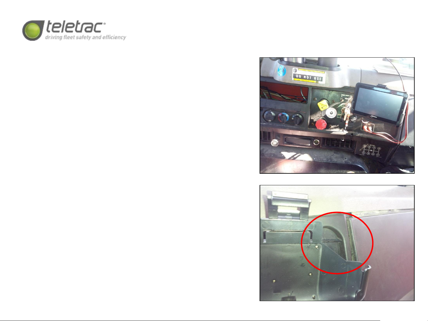
Sterling LT Series- CTO and FIL Location
The CTO7 is installed on the blank panel of
the center dash, as shown at top right. The
FIL is installed in the smaller blank panel
below the CTO7, to the left of the bank of
switches. A small relief notch is required to
be filed into the dash panel to allow passage
of the CTO7 data cable, as shown at bottom
right. Please ensure that adequate cable slack
is provided so that the driver may adjust the
CTO7 as needed.
Note: Please refer to the CTO7 mounting and
provisioning instructions for direction as to
how to mount and test the device’s
functionality. The CTO7 must be fully tested
prior to calling for verification.

Sterling LT Series- Power, Diagnostics,
and PTO Connections
Power Connections: As the 9-pin Deutsch connector provides
12 volt constant power, only the ignition sense requires an
external connection. The ignition feed is accessed from the
rear of the ignition switch, as show at top right. Many of the
wires are pink, thus a digital multimeter must be used to
verify the correct wire.
PTO Connection: While there is a PTO switch on the dash, it
does not provide an adequate output for the TM470J. The
best source for PTO is from the passenger’s side relay panel.
Carefully remove the panel and connect to the positive
output of relay #13, which is for the transmission. As nearly
all of the wires are pink, a digital multimeter must be used to
determine the correct wire. This wire will provide a positive
output, which must be inverted to a negative signal with the
provided relay, and then connected to the grey wire on the
TM470J wiring harness.
Diagnostic Connection: The 9-pin Deutsch plug is located on
the bottom of the dash, facing downwards, directly below
the ignition switch. Carefully remove the OEM port and
replace with the J-bus y-adaptor.

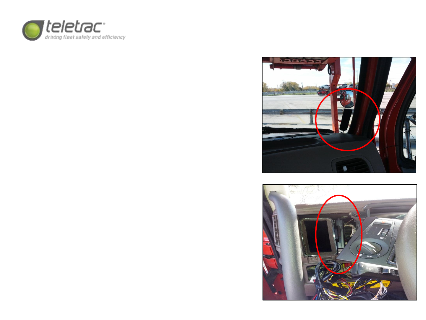
Sterling LT Series- Antenna
and Device Mounting
Antenna Location: The antenna will be mounted
to the lower passenger’s side corner of the
windshield, as shown at top right. Please ensure
that the antenna is oriented in the correct
direction, and that the windshield has been
thoroughly prepped with an alcohol wipe prior to
mounting the antenna.
Device Location: The TM470J is mounted directly
behind the keyswitch panel to the HVAC vent
using two screws, as shown at bottom right.
NOTE: After verification, please ensure that all
connections on the device and in the vehicle are
tamper-sealed using the provided Torque Seal.

Mack CH Series
Mack CH Series- CTO and FIL Location
The CTO7 is installed on the blank panel of
the center dash, as shown at top right, above
the CB radio power connection point. The FIL
is installed in the same panel, to the left of
the CTO7, centered between and slightly to
the right of the air switches. A small relief
notch is required to be filed into the dash
panel to allow passage of the CTO7 data
cable, as shown at bottom right. Please
ensure that adequate cable slack is provided
so that the driver may adjust the CTO7 as
needed.
Note: Please refer to the CTO7 mounting and
provisioning instructions for direction as to
how to mount and test the device’s
functionality. The CTO7 must be fully tested
prior to calling for verification.
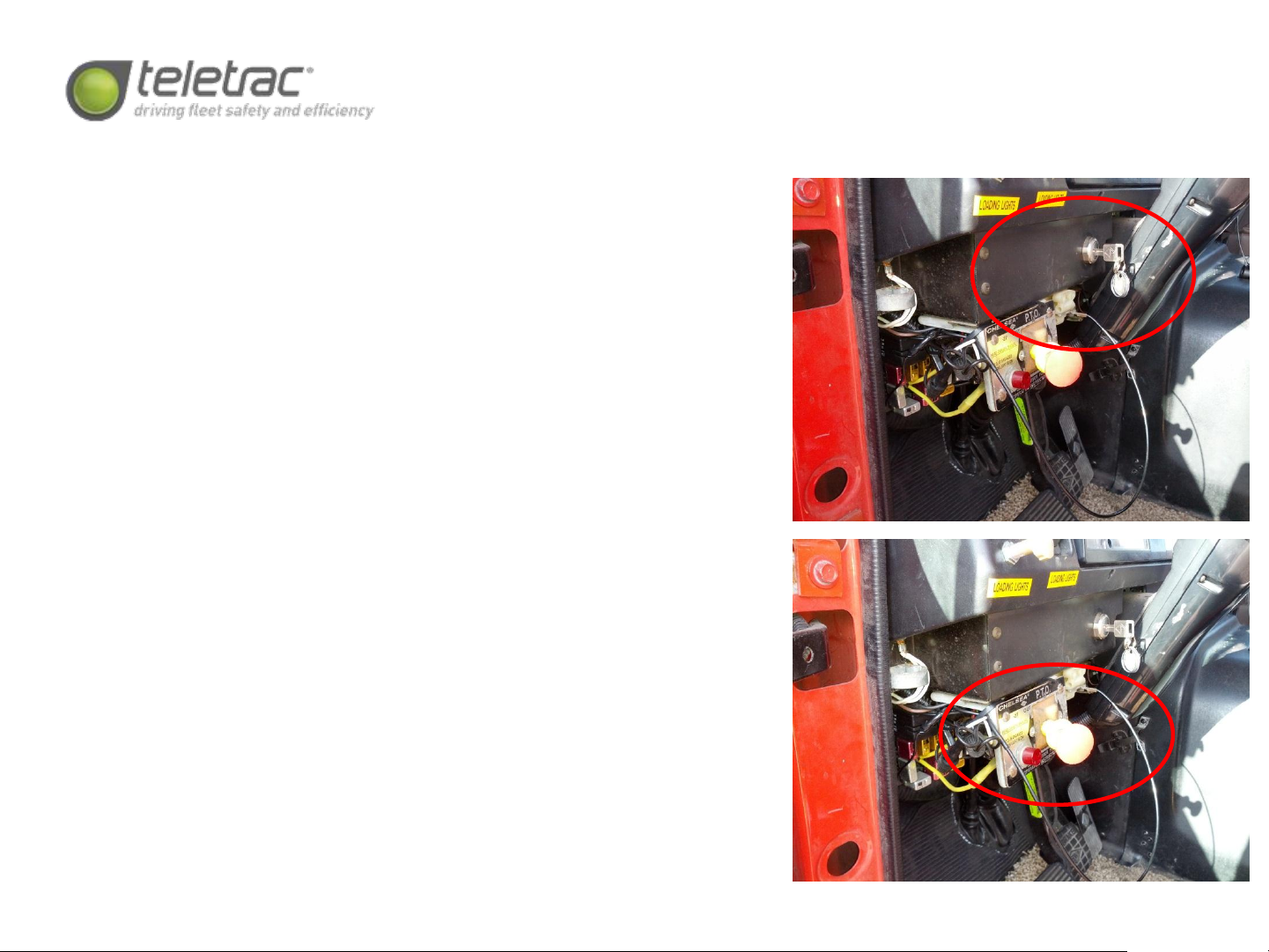
Mack CH Series- Power, Diagnostics,
and PTO Connections
Power Connections: As the 6 or 9-pin Deutsch connector
should provide 12 volt constant power, only the ignition
sense requires an external connection. The ignition feed is
accessed from the rear of the ignition switch, as shown at
top right. Many of the wires are white, thus a digital
multimeter must be used to verify the correct wire.
PTO Connection: The aftermarket PTO switch is located on
an L-bracket on the bottom of the driver’s side dash. Wire
colors vary, but the output signal is negative, which must
be verified with a digital multimeter. Once the correct
signal wire is determined, it will be connected to the grey
wire of the TM470J wiring harness.
Diagnostic Connection: The 9-pin Deutsch plug is located
on the bottom of the dash, facing downwards, directly
below the ignition switch or on the lower driver’s side
kickpanel. Carefully remove the OEM port and replace with
the J-bus y-adaptor.
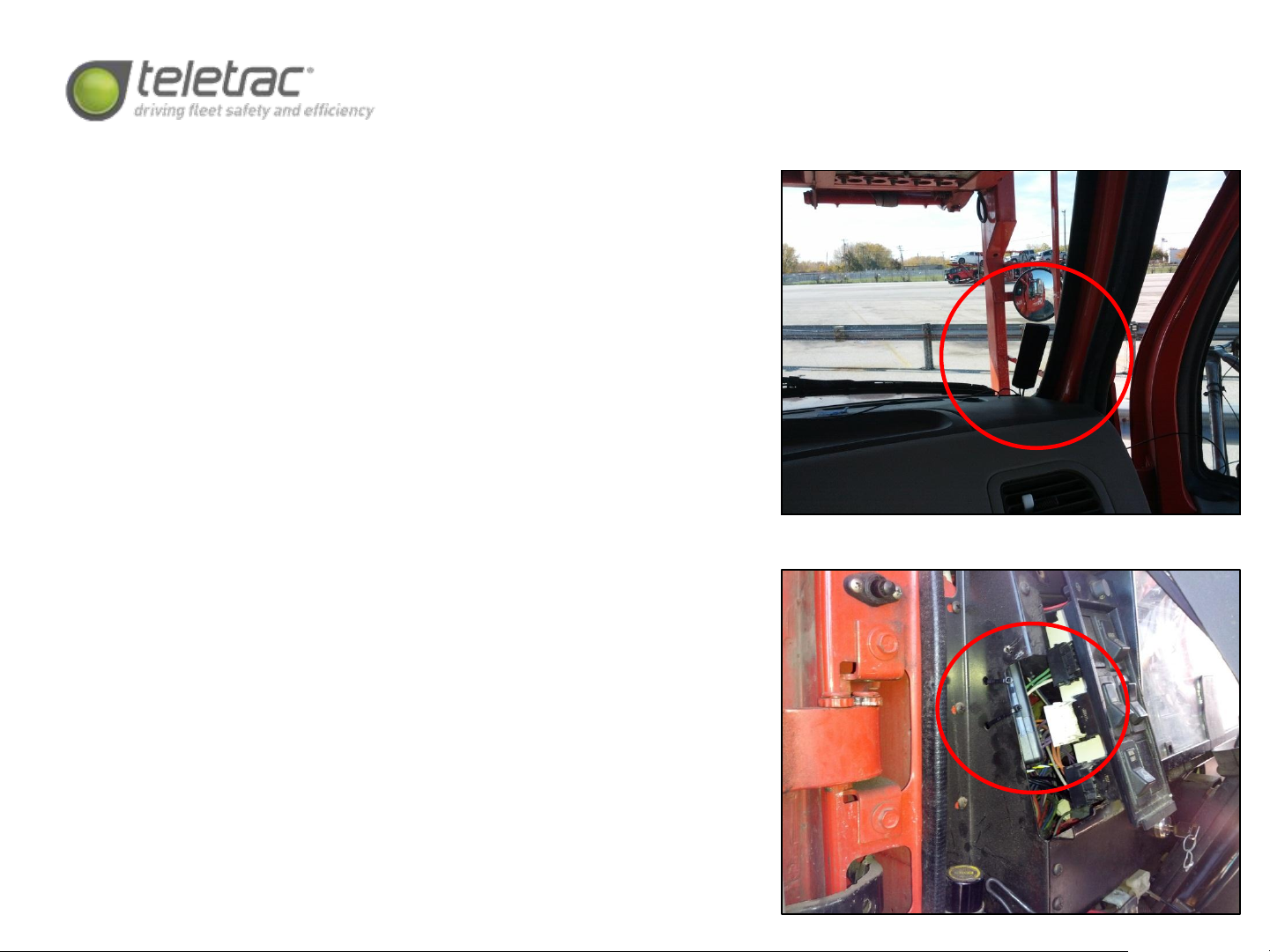
Mack CH Series- Antenna
and Device Mounting
Antenna Location: The antenna will be mounted
to the lower passenger’s side corner of the
windshield, as shown at top right. Please ensure
that the antenna is oriented in the correct
direction, and that the windshield has been
thoroughly prepped with an alcohol wipe prior to
mounting the antenna.
Device Location: The TM470J is mounted with
two zipties to the metal side panel behind the
lightswitch panel, as shown at bottom right.
NOTE: After verification, please ensure that all
connections on the device and in the vehicle are
tamper-sealed using the provided Torque Seal.

Volvo ISX Series
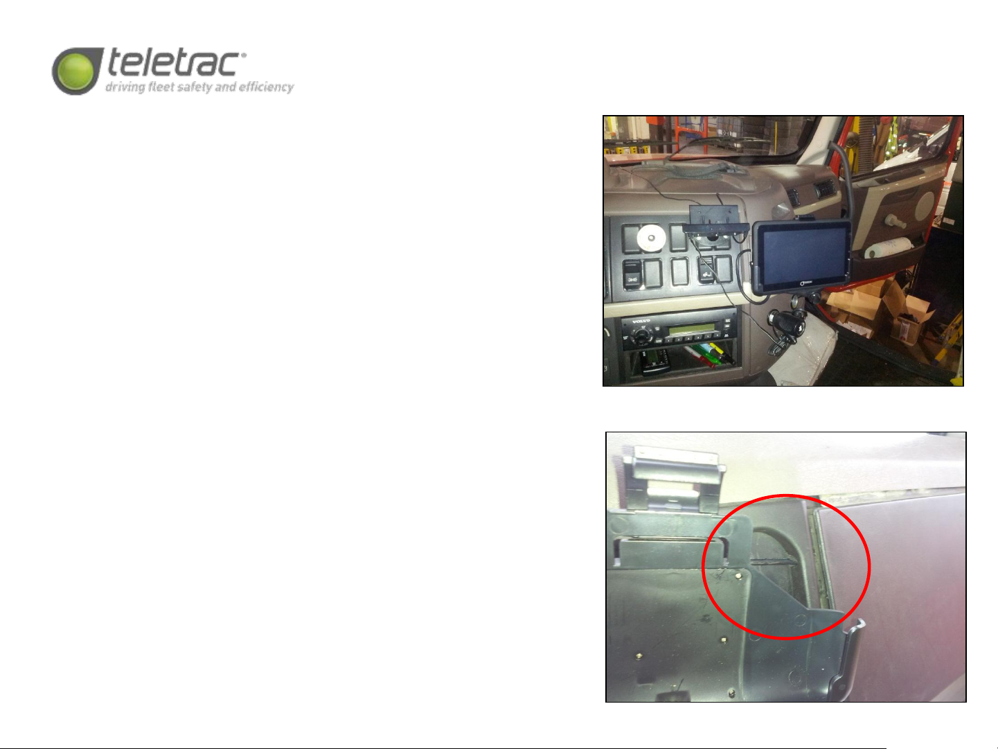
Volvo ISX Series- CTO and FIL Location
The CTO7 is installed on the blank panel, just
below the passenger’s side cupholder.
Please ensure that the CTO7 is installed just
low enough that it can be tilted forwards for
fusebox access. The FIL is installed into one of
the blank knock-outs, just above the radio
and to the left of the CTO7. A small relief
notch is required to be filed into the dash
panel to allow passage of the CTO7 data
cable, as shown at bottom right. Please
ensure that adequate cable slack is provided
so that the driver may adjust the CTO7 as
needed.
Note: Please refer to the CTO7 mounting and
provisioning instructions for direction as to
how to mount and test the device’s
functionality. The CTO7 must be fully tested
prior to calling for verification.
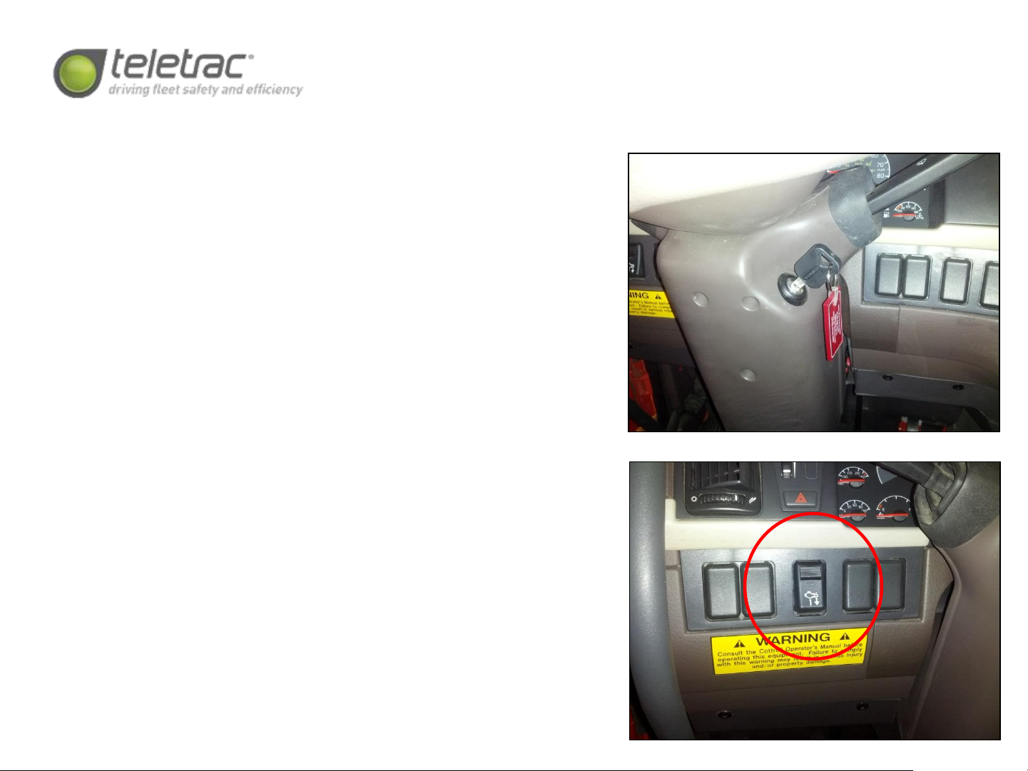
Volvo ISX Series- Power, Diagnostics,
and PTO Connections
Power Connections: As the 6 or 9-pin Deutsch connector
should provide 12 volt constant power, only the ignition
sense requires an external connection. The ignition feed is
accessed from the rear of the keyswitch on the steering
column. As many of the wires are the same color, a digital
multimeter must be used to verify the correct wire. It is also
acceptable to access ignition power from the bottom of the
relay panel, located at the top-centre of the dash.
PTO Connection: The OEM PTO switch is located on the
lower lefthand side of the driver’s dash. Wire colors vary,
but the output signal is positive, which must be verified with
a digital multimeter. This wire will provide a positive output,
which must be inverted to a negative signal with the
provided relay, and then connected to the grey wire on the
TM470J wiring harness.
Diagnostic Connection: The 9-pin Deutsch plug is located on
the bottom of the dash, facing downwards, adjacent to the
driver’s kickpanel. Carefully remove the OEM port and
replace with the J-bus y-adaptor.
Volvo ISX Series- Antenna
and Device Mounting
Antenna Location: The antenna will be mounted
to the lower passenger’s side corner of the
windshield, as shown at top right. Please ensure
that the antenna is oriented in the correct
direction, and that the windshield has been
thoroughly prepped with an alcohol wipe prior to
mounting the antenna.
Device Location: The TM470J is mounted to the
HVAC vent behind the headlight panel with two
12” zipties, as shown at bottom right.
NOTE: After verification, please ensure that all
connections on the device and in the vehicle are
tamper-sealed using the provided Torque Seal.
This manual suits for next models
3
Table of contents
Other Teletrac Automobile Accessories manuals


Popular Automobile Accessories manuals by other brands

Mishimoto
Mishimoto MMRAD-NEO-01 install guide

Dakota Digital
Dakota Digital LED Tail Lights for 1969 Mustang LAT-NR372 installation instructions

BASETech
BASETech Head Up Display X5 operating instructions

ACV
ACV 381094-22 installation manual

Front Runner
Front Runner TRCA008 manual

Thule
Thule Rapid System 1846 instructions


