Page 2of 3
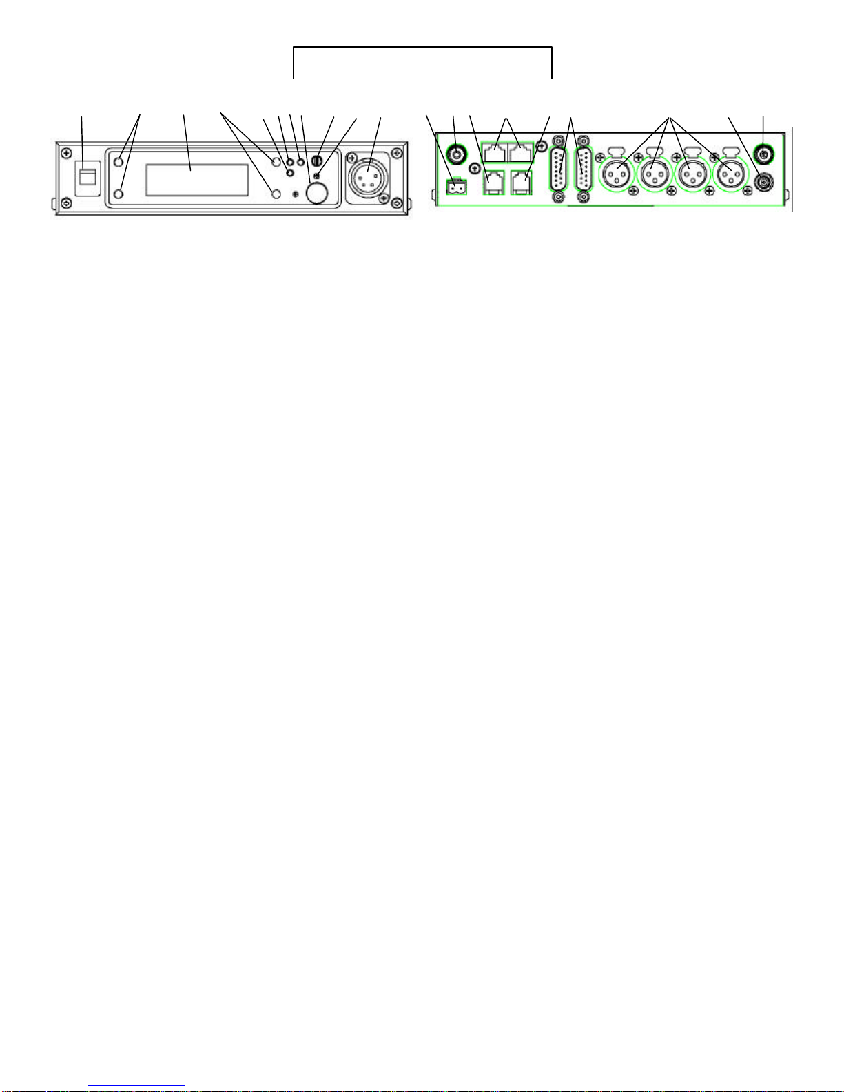
1. On/Off Switch –Turns the base station on/off.
2. [MENU] and [SET] buttons –Used to select menus and set options on the
LCD.
3. Backlit LCD.
4. [UP] and [DOWN] buttons -Used to select menus and set options on the
LCD.
5. Peak Aux Level Light –Will flash red when the auxiliary input level into
the base station is too high.
6. Peak Intercom Level Light –Will flash red when the intercom input levels
into the base station are too high.
7. Talk Light –Green when the talk button is active. Will turn red when the
microphone level into local headset is too high.
8. Talk Button –Press to enable the audio path from the headset.
9. Headphone Volume –Used to adjust the volume level out to a headphone.
10. Microphone Gain –Adjusts the audio gain from the local headset
microphone.
11. Local Headset Jack
Pin 1 = Ground
Pin 2 = Microphone (Hot)
Pin 3 = Audio Out +
Pin 4 = Audio Out -
12. Relay Contacts –Normally Open. When activated they close.
13. Receive Antenna Connector –TNC Female connector. The color dot
near the connector must match the color of the antenna.
14. Auxiliary Connector –RJ-11 connector used to connect auxiliary
audio into and out of a base station.
15. CAN bus –RJ-45 connectors used to connect a base station to a CAN
type of bus.
16. Matrix Connector –RJ-11 connector used to connect balance 4-W
audio into and out of the base station.
17. Intercom Loop Thru –Two DB15 connectors used to loop intercom
audio thru a base station.
18. Intercom Jack –XLR intercom jack to allow audio into the base via
XLR connectors instead of DB15 connectors.
19. Power Connector –Input power jack which requires 12 to 15 Volts
AC or DC at 1000 mA.
20. Transmit Antenna Connector –TNC Female connector. The color
dot near the connector must match the color of the antenna.
Controls and Connections
1
2
3
4
7
8
6
5
9
10 11 13
12 15
14
16 17 18 19 20


