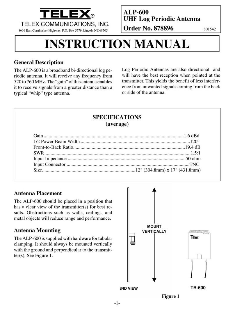
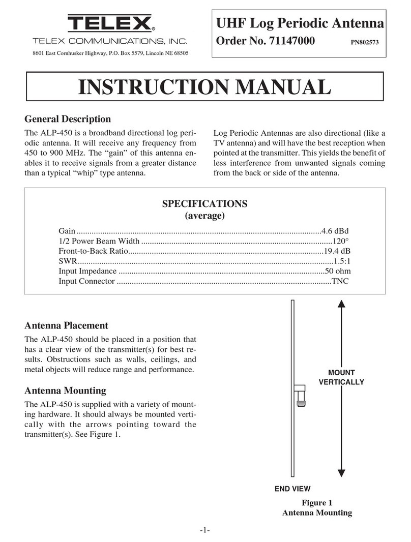
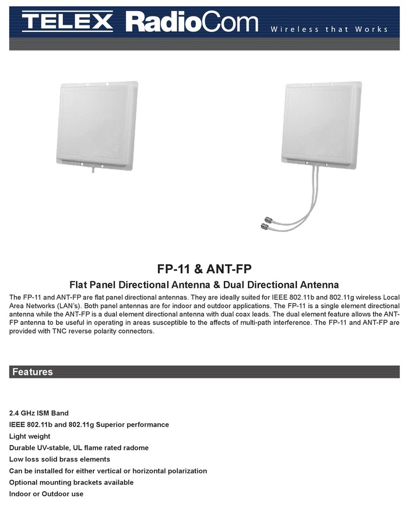
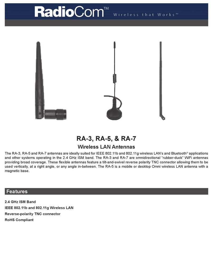
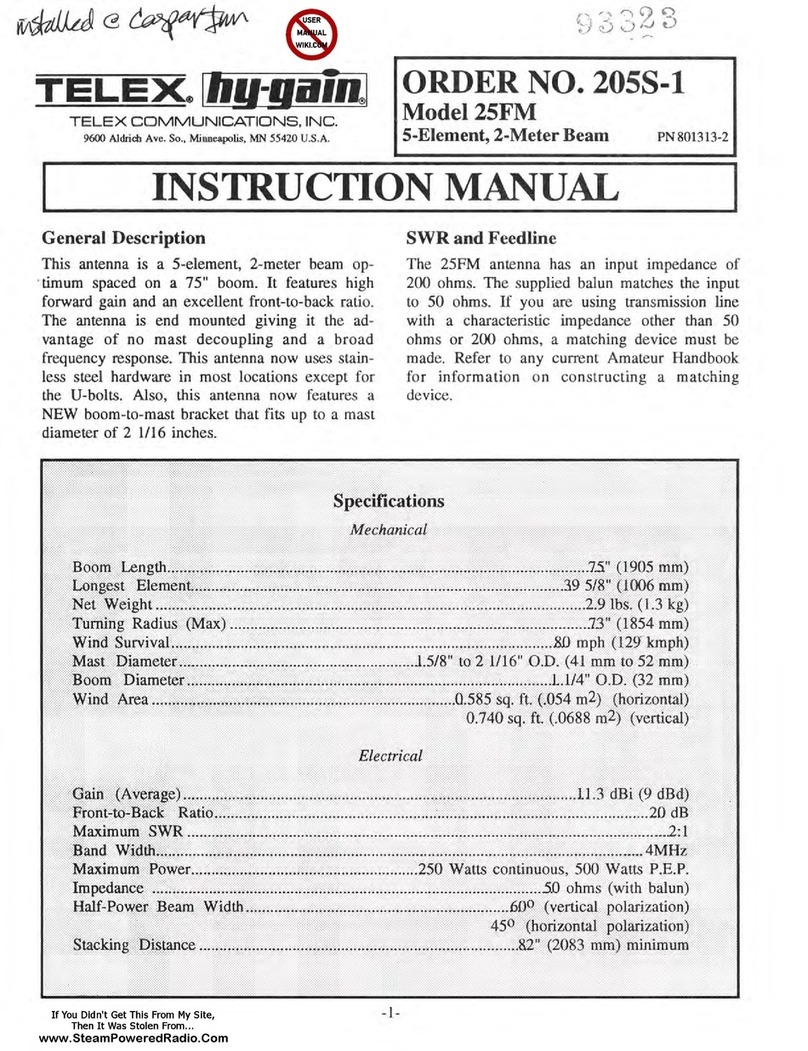
Telex hy-gain 214FM User manual

www.SteamPoweredRadio.Com
TELEX®
llig-gaipJ
TELEX
COMMUNICATIONS.
INC.
9600AldrichAvc.
So.i
Minneapolist
MN
55420U.S.A.
ORDER NO. 214S-1
Model214FM
14
..
Element,
2-Meter
Beam
PN
801316-3
INSTRUCTION MANUAL
!.t,
..
07
,
34
N
II
l1.,;
03,
4
11.!
w
l/11~
I
,,
Figure
I
Overall
View
GENERAL
DESCRIPTION
This
antenna
is
a 14-e
lement
, clo e-spaced,
two
m
ter
beam.
It
features
high
forward
gain
associa
ed
with
a
narrow
beam
w·
dth.
It
has
an
excellent
front-to-back
rati
and
is
especially
suited
for DX
ontacts
where
maximum
gain
and
a
narrow
beam
width
is
required.
The 214FM antenna now features stainless
steel hardware for all electrical and most
mechanical connections, and a
NEW
boom-to-
mast bracket that
will
fit
mast
diameters up
to
2
1/16 inches.
SPECIFICATIONS
Mechanical
Boom
Length
. .
..............
15'6" (4.72
m)
Longest
Element
........
. . 39½"
(1003
mm)
Turning
Radius (maximum) . . . . . . 95"
(2.41
m)
Wind
Survival
..
.
........
80
mph
(129 kmph)
Mast
Diameter
........
, . . . 15
/s"
to
2½6'
1
0 .D.
(41
mm
to
52
mm)
Boom
Diameter
..........
I¼"
O.D. (32
mm)
Wind
Area
....
........
1.65 sq. ft. (vertical),
1.28
sq
ft.
(horizontal)
Net
Weight
.............
5.5
pounds
(2.5 kg)
Electrical
Gain
..................
~
.15.2
dBi
13.0
dBd)
Front-to-Back
Ratio
..................
.
20
dB
Maximum
SWR
.......................
2:1
Band
Width
.......
.
............
.
..
.
4
MHz
Maximum
Power.
. . . . . . 250
watts
continuousJ
500
watts
P.E.P.
Impedance
......
.
..
.
.....
50
ohms
(with balun)
Half-Power Beam Width
.......
. ..
&5°
(vertical,
horizontal polarization)
Broadside Stacking Distance. . . . . . .. . 12' max.,
6'10''
min.

www.SteamPoweredRadio.Com
TELEX
®
llig-gainJ
TELEX
COMMUNICATIONS,
INC
.
9600 Aldrich Ave. So., Minneapolis,
MN
55420U.S.A.
ORDER NO. 214S-1
Model214FM
14-Element,2-MeterBeam PN
801316-3
INSTRUCTION MANUAL
~
012,33S.,,,"
,:,,,,.
·
\\\
\
010,
3::;.-.
:::;··
.,,,
..
09,
33
....
•I,,,,
..
08,
33
....
.•
.....
·
07,
3
4•,
.,,,.·
06,
34
1
/o"
I "f,o"
I
,,
Figure
1
Overall
View
GENERAL
DESCRIPTION
This
antenna
is
a 14-element, close-spaced,
two
meter
beam.
It
features
high
forward
gain
associated
with
a
narrow
beam
width.
It
ha
s
an
excellent
front-to-
back
ratio
and
is
especially
suited
for DX
contacts
where
maximum
gain
and
a
narrow
beam
width
is
required.
The
214FM antenna now features stainless
steel hardware for all electrical and most
mechanical connections, and a
NEW
boom-to-
mastbracketthatwill
fit
mastdiameters up to 2
1/16
inches.
SPECIFICATIONS
Mechani
c
al
Boom
Length
................
15'6" (4.72
m)
Longest
Element
..........
39W'
(1003
mm)
Turning
Radius (
maximum
) . . . . . . 95"
(2.41
m)
Wind Survival
...........
80
mph
(129
kmph
)
-1-
Mast
Diameter
............
1¾"
to
21/16"
O.D.
(41
mm
to
52
mm)
Boom
Diameter
..........
1
¼" O.D.
(32
mm)
Wind
Area
............
1.65
sq.
ft. (vertical
),
1.28
sq.
ft.
(horizontal)
Net
Weight
.............
5.5
pounds
(2.5 kg)
Electrical
Gain
......
..
..........
. . 15.2
dBi
(13.0 dBd)
Front-to-Back
Ratio
..................
20
dB
Maximum
SWR
.............
...
.....
...
2:1
Band
Width
........................
4
MHz
Maximum Power. .. . . . . 250
watts
continuous,
500 watts P.E.P.
Impedance
..............
50
ohms
(with balun)
Half-Power Beam Width
.........
35° (vertical,
horizontal polarization)
Broadside Stacking Distance. . . . . . . . . 12'
max.,
6'10'' min.

www.SteamPoweredRadio.Com
on
011
D10
09
oe
01
06
FRONT
BO
OM
RI
REAR
BOO
M
Figure
2
Element
Spacing
on
Booms
SWR
AND
FEED
LINE
The 214FM antenna bas
an
inputimpedance
of
200 ohms.
The
supplied balun matches the
input to 50 ohms.
If
you are using transmission
linewith a characteristics impedance
other
than
50 ohms
or
200 ohms, a matching device must
be made. Refer to any current Amateur Hand-
book for information
on
constructing a
matching device.
TUNING
NOTE:
The
Driven
and
Parasitic
Elements
are
adjusted
independently
in
the
following
manner:
Parasitic
Elements:
This
antenna
is
pretuned
for
maximum
gain
and
best
radiation
pattern
at
146
MHz.
This
setting
will give
optimum
performance
over
the
entire
144-148
MHz
band.
If
you
wish
to
optimize
the
antenna
for a
frequency
higher
than
146
MHz,
cut¼"
off
of
the
total
element
lengths
for
each
MHz
higher
than
146.
Driven
Element:
SWR
can
be
lowered
to
less
than
1.2:1
at
a
desired
frequency
by
carefully
trimming
the
driven
element. Keep
the
element
symmetrical
by
cutting
the
same
amount
from
each
side.
Typical
SWR
curves
are
shown
in
Figure
3A
and
a
cutting
chart
is
shown
in
Figure
3B.
Each
installation
is
slightly
different,
so
cut
the
driven
element
for
the
lower
SWR
at
your
particular
location
.
Measure
the
SWR
as
close
to
the
antenna
as
you
can
for
accurate
results
.
-2-
"
LO
a:
,...
~
..
I-
I-
...-
....
I OMI
•••
MM1
-----
..
,
...
lltlol1--
Mt•,-
·- -
IT
i::i:
!ff
±ill
w
UM
!lH
1:
,,1,
·-
.t".
t:.
;._.
P-
-'
I/ -·
---
~
•-
-~
,..,
--,-+
I-
. 1---
·••
~
--i---.
1-r
>-
•
,___
...
,-
......
--
...
~
~
t
w;.!1
~
1
-=::~
r:;:
1
i rr
r-
T -
-
Figure
3A
VSWR
for
Horizontal
Polarization
Only
j
-~
.£
17
..
j
l
E
.;
161
,lz
C:
•
·!
..,
'15
16
t
..J
...
AO
·
0214
·
.l-006
....
r-,
....
....
-
r--
-
,..
144 145 146
147
148
FREQUENCY
IN
MHz
Figure
3B
Driven
Element
Cutting
Chart

www.SteamPoweredRadio.Com
AO-OltC,C.·001
Figure
4
Vertically
Polarized
Broadside
Stacking
Configuration
for
FM
Operation
STACKING
This
antenna
can
be
easily
stacked
for
approximately
3
dB
more
gain
each
time
the
number
of
yagi
is
doubled. Refer
to
Figure
4
for
stacking
and
phasing
harness
cutting
information.
The
two
phasing
lines
coming
from
the
two
antennas
to
the
"T"
connector
can
be
any
odd
multiple
of
one-quarter
wavelength
in
the
75-
ohm
transmission
line
. See
Figure
5.
NOTE:
When
phasing
two
antennas
,
the
Driven
Element
halves
that
are
connected
directly
to
the
phasing
lines
should
be
on
the
same
side
of
the
array
.
The
feedline
impedance
is
for
50-ohm
coax
(RG-213
/
u).
For
detailedinformation
on
stacking
more
than
two
yagis,
please
consult
any
current
Amateur
Handbook.
A0-0214
· A-
005
ANTENNA
END
RG-1I/U
OR
ANY 7
5-OHM
COAX
ll.
120
'
4
I~\
• 146~'4°
'3/ •
173'ti
"'
15
A •
200'14
"
4
Figure
5
Coaxial
Cable
Length
for
Phasing
-3-

www.SteamPoweredRadio.Com
INSTALLATION
This antenna fits a 2
11
O.D
. mast. A 2
11
O.
D.
gal-
vanizedpipeis recommendedfor a sturdymast.
Mount the
antenna
in
the
clear. Surrounding
objects-particularly power lines and
other
ob-
jects
of
considerable mass
or
length-are
detrimental
to
the
performance
of
the antenna.
WARNING
Do
not
allow any part
of
the antenna to
touch power lines. This could cause severe
bums
or
fatal injuries.
When mounting
the
214FM with an
HF
beam
antenna
on
the
same
mast,
the
214FM should
be
on
top.
If
the
214FM is to
be
vertically
polarized, separation of
the
two antennas
should
be
at
least 2 feet.
If
the
214FM is
to
be
horizontally polarized, separation should
be
at
least6feet.
The
mast,
if
metallic, should never
be
run
com-
pletely through
the
plane
of
the
elements.
Slightly reduced performance will
be
noticed if
a vertically polarized 214FM is mounted
at
the
top
of a metallic mast as shown
in
Figure
1.
Horizontally polarized mountingwill
not
be
af
-
fected.
For
optimum performance with a
vertically polarized 214FM, a wooden mast
should be used, and
the
coax routed past the
reflector
then
dropped
to
the
mast.
The
antenna can
be
mounted either vertically
or
horizontally for
FM
or
SSB/CW operation
respectively. Circular polarization can
be
ob-
tained
by
using two yagis.
For
information
about which polarization
to
use, consult local
Amateurs who
use
the frequencies you desire.
-4-
STEP-BY-STEP
ASSEMBLY
Remove
the
parts
from
the
carton
and
check
them
against
the
Parts
List
and
the
illustrations
.
Select
the
boom-to-
mast
backup
plate
(Item
No. 6),
the
boom
-
to
-
mast
clamp
(Item
No
. 5)
and
the
four
(4
) ¼"-20 x
¾"
bolts,
¼"
lockwashers
and
nuts
(Item
Nos.32, 33
&
34).
Place
the
boom-to-
mast
clamp
on
the
boom
as
shown
in
Figure
6.
The
front
and
rear
boom
sections
should
meet
in
the
middle
of
the
boom-to-
mast
clamp.
Use
the
¼"-20 x ¾"
bolts
in
the
outside
holes
.
Leave
the
inside
holesfor
the
two
(2) U-bolts,
which
willbeused
later
for
mounting
the
mast.
Select
either
the
vertical
or
horizontal
mounting
position.
Adjust
the
boom
accordingly
before
tightening
the
bolts
securely.
Select
3
/i6"
x
39
½"
Rl
aluminum
tubing
(Item
No. 7).
Use
a pencil
to
place
a
mark
at
the
center
of
the
tubing
(19¾" from
either
end).
Pla
ce
two
more
marks
5
/s
" from
each
side
of
the
cent
er
mark.
Place
a #10-24x 1½"
eyebolt(Item
No.27)
into
the
Rl
slot
as
shown
in
Figure
6, Detail A.
Slide
the
Rl
through
the
holes
and
the
eye
bolt
until
the
outer
two
marks
on
theRl
are
visible
on
each
side
of
the
boom. Slip
on
an
aluminum
half
washer
(Item
No
. 23), a
lockwasher
(Item
No. 30)
and
a #10
nut
(Item
No. 31).
Tighten
it
just
enough
to
hold
the
rod
securely. DO
NOT
OVERTIGHTEN.

www.SteamPoweredRadio.Com
25
Item
No.
1
2
5
6
25
32
·---
---
..
___
~--
~
--
------
1~
..
~;---
SEE
DETAIL 8
-----
/
2 /
/__
I
SEE DETAIL A
--..
"
ll.;:;.-=-=--
-
De
s
cription
Boom,
Rear
, 1¼'' x 93"
Boom,
Front
, 1¼" x 93"
Cla
mp
, Boom-to-Maet
Backup
Plate
, Boom-to-Mast
Ca
plug
,
I¼",
bl
ack
B
olt,
h
ex
head,
l/4''-20
x %"
Item
No
.
33
34
35
36
37
D
esc
ript
io
n
Loc
kwasher
.
internal,
¼''
Nut
,
hex,
¼"-20
U-
Bolt
,
~/16'
1-18 x 3%"
Lockwash
er,
split,
5
/16"
Nut,
hex,
5
/15
11
-18
Figure
6
Boom-to-Mast
Clamp
Assembly
'
I
I
I I
A0-0214
-A-00
8
Item
No.
De
scription
A0
-
0214-8
-
009
11
3
1.
"
ELEMENT
LJ/
16
23
Half
Wash
er,
aluminum
27
Eyebolt,
5
/1~",
#10-24 x 1
½"
30
Lockwa
she
r,
internal,
#10
•
I I
Figure
6 -
Detail
A
Element
Assembly
-5-
31
Nut,
hex
,
1110-24

www.SteamPoweredRadio.Com
Item
No.
3
4
20
21
22
24
28
TIIP
E ( 3
PL
ACES)
Description
Driven
Element
,
7
/ 1
&"
x 1
71/4''
Beta
Rod, 2
1/2''
Balu
n
Assembly
Insulator
(
Driven
Element-to-Boom)
B
eta
Clip
Caplug
,
'/
16"
,
with
hole,
black
Item
No.
26
28
29
30
31
Description
AO
·
0214
·B
·OIO
I>-
(j
-
- BRAID
Screw,
pan
head,
#10 x
%",
Type
A
Bolt,
hex
head
, #10-24 x l
1
fl'
Bolt,
hex
head
, #10-24 x 2½"
Lockwasher,
internal
, #10
Nut
, hex, #10-24
F
igur
e 6 -
Detail
B
Driven
Element
Assembly
Select
the
element-to-boom
insulator
(Item
No. 21), two sections
of
the
ifis"
x 17¼''
Driven
Element
(DE)
(Item
No.
3)
and
the
beta
rod
(
Item
No.
4).
See
Figure
6,
Detail
B.
NOTE:
If
50
ohm
coaxial
cable
is
used
to
feed
the
antenna,
select
the
supplied
balun
at
this
time.
Use
the
#10-24 x 2½"
bolt
(Ite
m No. 29)
to
faste
n
the
element-to-
boom
insulator
to
the
boom. Refer
to
Figure
6,
Detail
B.
Use
the
two
(2) #10-24x 1½''
bolts
(Item
No.
28)
to
assemble
the
Driven
Element
as
shown
in
Figure
6,
Detail
B.
Pay
particular
attention
to
the
connections
of
the
beta
rod,
balun
and
feedl
in
e.
Waterproof
the
coax
connection
with
Coax-
Seal
®
or
some
similar
substance.
Install
capl
ug
s
on
the
ends
of
the
boom
and
the
Driven
Element.
Use
the
#10 x
3/s
"
screw
(Item
No. 26)
to
fasten
the
b
eta
rod
shorting
clip
(Item
No. 22)
over
th
e
beta
rod
as
shown
in
Figure
6,
Detail
B.
Coax
-
Seal
®
i.s
a
registered
trademark
of
Universal
Ele
c
tronics
,
In
c.
-
6-

www.SteamPoweredRadio.Com
Select
the
following rods: D1 (34¾"
long
,
Item
No. 8), D2 (34%" long,
Item
No. 9), D3 (34½"
long
,
Item
No. 10),
D4
(343/s"
long,
Item
No.
11),
D5
(34¼"
long,
Item
No. 12), D6
(341/s''
long,
Item
No. 13),
D7
(34" long,
Item
No. 14),
D8
(333/s"
long,
Item
No. 15), D9 (33¾"
long,
Item
No. 16), D10 (33%" long,
Item
No. 17),
D11 (33½" long,
Item
No. 18),
and
D12
(333/s"
long,
Item
No. 19).
Mark
the
center
point
on
each
rod,
then
make
two
more
marks
%"
on
either
side
of
the
center
mark.
Secure
the
elements
to
the
boom
as
shown
in
Figure
6
and
Detail
B.
Be
sure
they
are
oriented
as
shown.
Slip
the
two
U-bolts
(Item
No. 35)
into
the
boom
-to
-mast
bracket
and
fasten
it
to
the
mast
securely.
Tape
the
coax
feedline
and
balun
to
the
boom
and
to
the
mast.
Be
sure
to
insulate
any
connections
from
the
boom
or
the
mast.
This
completes
your
installation.
FOR
OUR
OVERSEAS CUSTOMERS:
The
United
States
uses
Ametican
units
of
measurement.
Please
see
the
information
belowfor assistancei~identify:
thi
:
hardware
~nd
components suppliedwith
the
product.
CONVERTING
AMERICAN
MEASUREMENTS
T~i~ETklc
. ' ,•: . .
..:
:::->.
Use
this scale
to
identify lengths
of
bolts, diameters
of
ti.lb~s, etc.
The
Arneri9aninch (1'')
and
foot (1')
can
be
converted
to
centimeters
in
this way: ·
··
·
1 inch
(1
11
) = 2.54
cm
1 foot (1') = 30.48
cm
Example: 42" x 2.54 = 106.7
cm
1 2 3 4 5 6
I~
l,1
!
1\
,,I
11,1
\,,,,~ii
11,,
,,,
l
,,11,\
~,
,i
1,,
,\
,!
'11
ii
11
l,1
I,
IA
1',!
I,
I!
I,
I
!1
I,,
,I
11
I
hi
I
I,,,,,
1,,1,,,
,,
'1
l,1
\1J
11h
111
l,1
/
1A1
,l
1,
1,
I
METRIC
I 2 3 4 5 6 7 8 9
10
11
12
13
14
15
-7-

www.SteamPoweredRadio.Com
Item
No.
1
2
3
4
5
6
7
8
9
10
11
12
13
14
15
16
17
18
19
20
21
22
23
24
25
26
27
28
29
30
31
32
33
34
35
36
37
Part
No.
170390
17
03
87
175157
170389
385
142-1
385
144
-1
160037
160024
16
0025
160026
1600
27
160028
160029
160030
160031
160032
160033
160034
160035
871704
46
5420
872072-1
163266
1
70
37
6
475639
455630
5
1067
0
5400
65
500
159
500
164
565
697
554071
505266
562961
5540
99
54
0067
564792
5557
47
PRJNrED
IN U.S.A.
Copyright101989
by
Telex
TELEX
COMMUNICA
TI
ONS, INC.
All rights resetved.
16MA
Y 1989
PARTS
LIST
Desc
r
iption
Qty
Boom
,
Re
ar, 11
/4"
x
93
" .
..
. . . . . .
..
.
...
..
.
...
. . .
..
..
. _
..
....
..
. . 1
Boom
,
Front
, 1¼" x
93"
.
...
....
...
. . .
..
...
. . . .
............
..
. . 1
Dr
i
ven
Element,
7
/16'' x
17
¼"
...
..
............
.
..........
.
....
..
2
Beta
Rod
, 2 1
/2
11
••••
••
• • • • • • •
•••
••
•••
•
••••
• • •
••••••
•
••
•••
• • •
••
••
1
Clamp,
Boom-to-Mast
..
.
....
.
...
.
..
.
.....
.....
........
...
.....
1
Backup
Pl
ate,
Boom
-
to
-
Mast
....
. . . . .
..
.
\'.~
.
....
.
....
.
.....
1
T b.
Rl
al
. 3'
//
39
1L
//
-,
,,.
/4- 1
u
mg
, ,
um1num
,
n6
x 12
.•••
.
?';:
.. .
.........
........
.
Tubing
,
Dl
,
alumin
u
m,
3/is11 x
34
¾"
..
...
?1
•
1
•••••••••••••••••••
• • 1
T b. D2 1 .
31
If
34
5
1."
~)::\/<)
I 1
u
1-ng,
, a
um1num
,
716
x
1a
..
. .
..................
..
..•.
T b. D3 1 . 3' "
34
1
.1."
.2.J?
; 1
u 1ng, , a
um1num,
n6
x
12
..
. . . ( . .
i--:
..
. .
...
...
..
. . . . . .
T b.
D4
1 . 3'
''
34
¾"
~)
.,..~
1
u 1ng, , a
um1num,
116
x a
.....
:
...
~
...
...
......
..
...
.
Tb
. D 1 .
a"
3
v11
?.)·,2-'
u
mg,
5,
a
um
1
num
,
½s
x 4
,4
......
...
. .
................
. 1
T b.
D6
1 .
31
II
34
1
/,1/
1:,'3 5' 1
u
1ng
, , a
um
1
num
,
116
x 18
....................•....•..
Tb
. D7 l .
31
" 34"
~:>'l"f'
1
u
1ng
, , a
um
1
num,
716
x
..................
.
......
..
..
.
T b. D8 l . 3 "
33
7
,,
2-.)
',,,'
u 1
ng
, , a
um1num
,
Vi6
x
1/s
......
,
...................
..
1
T b. D9 1 . 31
II
33
31
"
~)I
1
u 1ng, , a
um1num
,
116
x
14
•••.•
• •
•••••••••.•••..••••••
,:. :;;1 '
Tubing
,
Dl0
,
alumin
um, 3
/i6" x 33%"
.....
~-'
·.
~-
........
........
1
' • 3 " 1
If
~
~
2,/
'1
1
Tubmg
,
Dll,
al
ummum,
1/!6
x 33/2 .
....
-:-
.1
• • ' •
••••••
• • •
••
• • • • • • 1
• ' "
II
3
II
2.
...
":)'"C,>
Tubmg
,
D12
, al
ummum,
"/
1s
x
33
Vs
..•
....
1. •
...
.
..
. . . .
....
.
...
1
Ba
l
un
Assembl
y . .
....
.
...
...
..
. . .
....
.
......
.
...
. .
..
.....
.. ..
1
In
s
ulator
(Dr
iven
Ele
ment-to-Boom)
..
.
...
...
..
...
. .
.........
. . 1
Parts
Pa
ck 214S-1,
Stainl
e
ss
St
ee
l
.......
.
........
.
............
1
Beta
C
lip
....
.
.....
......
............
.
............
.
.........
1
Ha
lf
Washer
,
aluminum
..............
.
..
.....
......
. .
..
...
13
C
aplug,
7
/iG",
with
ho
le
, black
................................
2
Ca
plug
, 1
¼",
black
. .
...
...
. .
..
...
....
...
..
...
. . . . .
..
..
. . .
...
2
Screw,
pan
head
, #
10
x %'',
Type
A
.....
..
.....
..
......
....
..
1
Eye
bolt
, 5
/i611,
#10
-2
4 x 1½"
..
.
....
. .
....
...
.
...........
. .
..
..
13
Bolt,
hex
bead
, #10-24 x 1½"
..
...
........
..
.
....
...
..
. .
..
. . . 2
Bolt,
h
ex
head,
#10-24 x 2½
11
•••••••••
•••
••••••••
•
••••
•
••
•••
• 1
Lockwash
er, i
nternal
, #10
..
.
.........
....
.......
. .
.........
21
Nut
, hex, #10-24
................................
.
......
..
. .
20
Bolt,
hex
head
,
¼"
-20 x
¾"
.
..........
.
......................
4
Lockwasher
,
internal,
¼"
....
. . .
....
.
....
. .
.....
.
........
.
..
5
Nut
,
hex
, ¼"-20
.......
. . . . .
........
. .
...
.
....
.
..............
4
U-bolt,
5
/iG"-
18 x
35/s"
......
..
........................
.
....
. .
..
2
Lockwasher,
split
, 5/is"
..
...
....
.
..
. .
..
...
...................
4
Nut,
hex, 5/1611-18
...
..
....
.........
.......
............
.
......
4
-8
-
This manual suits for next models
1
Table of contents
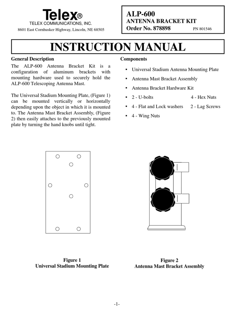
Other Telex Antenna manuals

Telex
Telex ALP-600 User manual

Telex
Telex ALP-600 User manual

Telex
Telex ALP-600 User manual

Telex
Telex ALP-600 User manual

Telex
Telex hy-gain 25FM User manual

Telex
Telex RadioCom RA-3 User manual

Telex
Telex ALP-600 User manual

Telex
Telex RadioCom ANT-FP User manual

Telex
Telex ALP-450 User manual

Telex
Telex 26012-20V-N Instruction manual