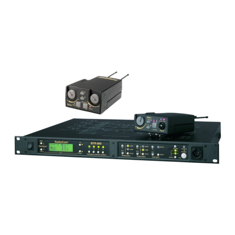
SPECIFICATIONS
TR-200
Overall
PowerRequirements
.........................................................
6
AA
cells (Alkaline,
NEDA,
MN
1500)
Nickel Cadmium Optional
CurrentDrain
................................................................................................................
typc 65
mA
TemperatureRange
.............................................................................
4
to 130'~(-20'~to 55'~)
Dimensions
...........................................................................................
4.25" W
x
4.125" H x 2.0" D
(108mm
x
105mmx 51mm)
Weight
........................................................................................................
1302(369g)with batteries
TransmitAntenna
.........................................................................................
114-wavewire (attached)
ReceiveAntenna
..........................................................................................
114-wavewire (attached)
Transmit
-
RF
Frequency Range
.....................................................................................................
150-216MHz
RF
Frequency Stability
............................................................................
C Controlled,0.005%
RF
Power Output
........................................................................................................
50mW Typical
~.
Modulation
.........................................................
..........................................
FM,
5000
Hz
deviation,
115micro-seconds Pre-emphasis
.
.
ModulationLimter
.............................................................................................
InternalCompressor
Modulation Frequency Range
...........................................................................
300
to 5000Hz =dB
MicrophoneAudioInput
...........................................................................................
30 to 3500ohms
...
MicrophoneInput Sensluvlty
..............................................................
2 mV Dynamic,4 mV Electret
.
.
Radiated Harmonics and Spurious Emissions
.......................................................................
-45 dBC,
Exceeds FCC Specifications
FCC
.......................................................................................
Type Accepted Under Parts90and 74
%
Receive
RF
Frequency Range
.....................................................................................................
150-216MHz
RF
Frequency Stabiltiy
....................................................................
stControlled, O.QOS%Type
DualConversion Superheterodyne,
FM
...
RF
Sensihvity
..............................................................................
Lessthan 0.5 pV for 12dB SINAB
IF
Selectivity
.....................................................................................
3 dB at 30kHz (CeramicFilter)
. .
Image
Rejection
..........................................................................................................
70 dB or better
.
.
Squelch Quietmg
........................................................................................................................
90dB
SquelchThreshold
......................................................................................................
1.OpV (Internal)
cp-~~~~
~
.
~
~~~-
~~
~~~~~~~
-
--
~~
~
.................................................................................................................
I
Signal:io-No~seRaao 90dB
Audio Output
..................................................................................
32 mW into
600
ohms(Headset)
Distortion
.............................................................................................
Less than 1% at Rated Output
FCC
..........................................................................................................
Notification Under
Part
15
