Telguard TG-7 Series User manual
24 HOUR ZONE (N.C.)
TELCO DIALER
ANTENNA
T
R
www.Telguard.com
REFER TO INSTALLATION AND
OPERATING INSTRUCTIONS
MANUAL. THIS DEVICE COMPLIES
WITH FCC RULE PART 15.
SIM
1
2
3
4
5
Power LED
CAUTION: INCORRECT
CONNECTIONS MAY RESULT
IN DAMAGE TO UNIT.
EARTH
GROUND
LED Mode
Toggle Button
4
LEDs 2-5
Signal (dBm) NO
SVC < -110 > -110 > -100 > -90 > -80 > -70 > -60
RSSI (bars) NONE 1½1 2 2½ 3 3½
System Status LEDs (RSSI Mode)
OFF
BLINKING
ON
System Status
LEDs
Alarm Panel
1 FLASH = AC LOW/MISSING
2 FLASH = LBC LOW BATTERY
3 FLASH = LFC LINE FAULT
4 FLASH = NSC NO SERVICE
5 FLASH = RFC RADIO FAILURE
6 FLASH = DTF DIAL TONE FAIL
7 FLASH = PPF PNL PRES FAIL
LED 1
OFF NOT ACTIVATED
ACTIVATEDON
System Status LEDs (Normal Mode)
ACTIVATION DENIEDFLASHING
ACTIVATION
LED 2
OFF
FLASHING
SYSTEM
TROUBLE
NO TROUBLE
TROUBLE:
LED 3
OFF
ON
PANEL COMM PANEL ON-HOOK (PRIMARY)
PANEL ON-HOOK (BACKUP)
LED 4
OFF IDLE
WAITING FOR RESPONSE
FROM TMC
ON
ACTIVATION DENIEDFLASHING
TMC COMM
LED 5
OFF IDLE
RADIO INITIALIZINGON
RADIO COMMUNICATINGFLASHING
RADIO STATUS
Battery
Connector
Acceptable RSSI Range
AC
(12V 800MA)
Battery wire should
be at least ¼ inch
apart from AC wires
24 HOUR ZONE (N.O.)
2
345
7
GREEN
R
1
T
RED
INCOMING
TELCO
RJ31X
WARNING:
HIGH VOLTAGE
PRESENT ON PHONE
LINES.
DISCONNECT PRIOR
TO SERVICING.
TO EXTERNAL
TRIP INPUT
PANEL OFF-HOOKFLASHING
BATTERY
6
8
LED 6
LED 7LED 8
OFF NOT USED
OFF NOT ACTIVATED OR
RESTORED
NOT USED
TRIP INPUT
AC NOT CONNECTED TO UNIT
AC CONNECTED TO UNIT
OFF
ON
POWER LED
FLASHING LINK SUPERVISION ENABLED
(2 FLASHES EVERY 6 SECONDS)
TELGUARD
Digital TG-7
STC2
(N.C.)
STC1
(N.O.)
123 5 6 1 2
1 2 1 32
4
Optional
Battery
+
-
ACTIVATEDON
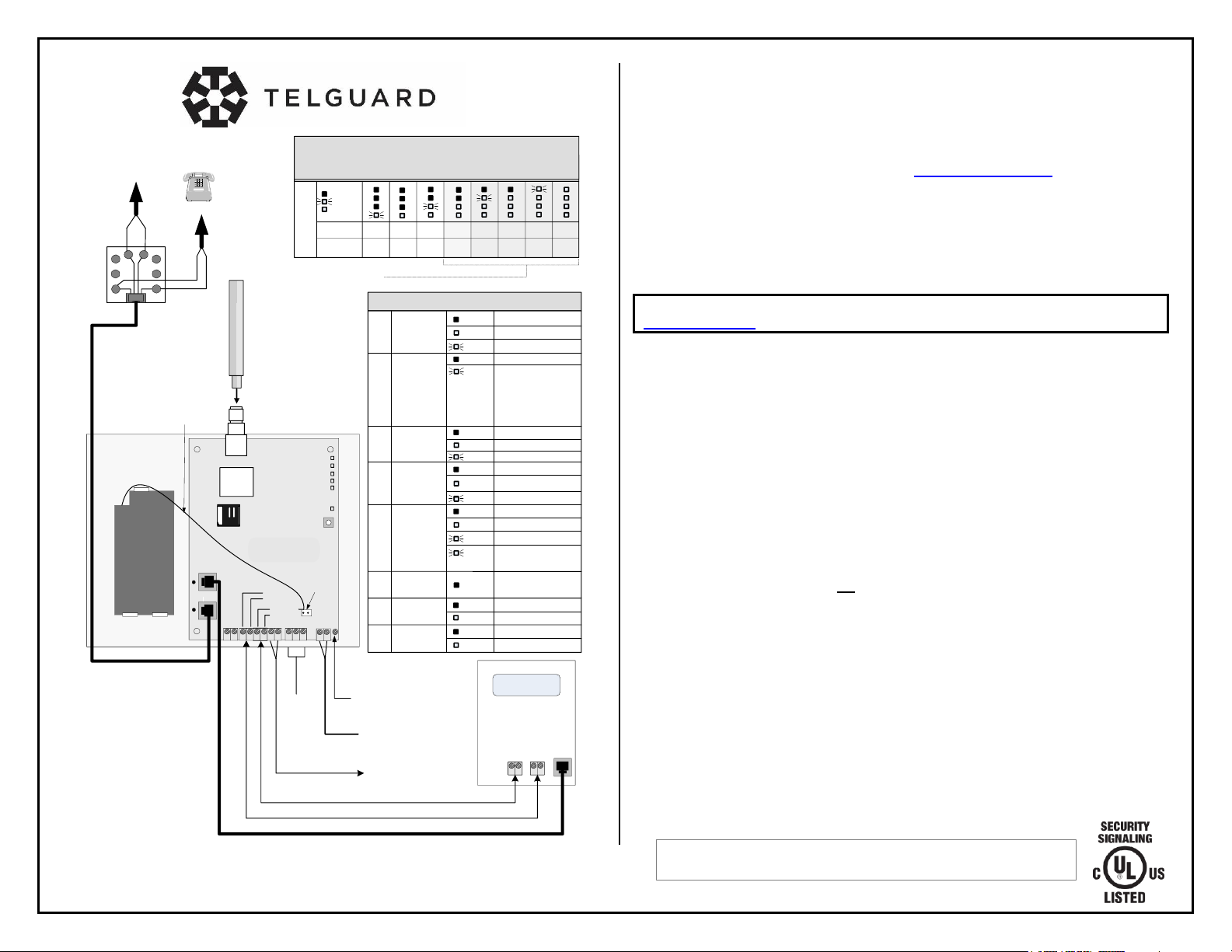
Telguard TG-7 Series
QUICK INSTALLATION GUIDE [BACKUP MODE]
NOTE: If a TG-PEM Power and Expansion Module accessory is part of your installation, referto the
full Installation and Operation Guide available from www.telguard.com/7install.
Installation Summary
There are seven steps in installing Telguard properly. IF YOU DO NOT
PROCEED IN THE ORDER AND MANNER PRESCRIBED, YOU MAY
NOT COMPLETE THE INSTALLATION IN THE TIME ALLOCATED.
STEP 1: REGISTER FOR CELLULAR SERVICE
The registration form may be completed online through our 24/7 dealer portal
www.telguard.com.
STEP 2: LOCATE UNIT AND MEASURE SIGNAL STRENGTH (RSSI)
First, you will be confirming that Telguard has adequate cellular signal strength. Press the
LED/RSSI Mode Toggle button one time, LEDs will now indicate signal strength. Minimum
recommended is 2 (2 on solid). Press the LED/RSSI Mode Toggle button a second time to exit
RSSI mode.
STEP 3: TRANSMIT PANEL ALARMS OVER THE TELCO CONNECTION
Next, you will verify that the alarm panel is programmed properly. This step is importantto verify
that the alarm panel is programmed with valid account code andcentralstation information
before transmitting signals through the cellular network.
STEP 4: PROGRAM,ACTIVATE &TRANSMIT PANEL ALARMS OVER THE
CELLULAR RADIO NETWORK
Next, you will be connecting the alarm panel's digital dialer output to Telguard and verifying that
alarm signalscan be reliably sent through Telguard over cellular to the central station digital
receiver. The incoming Telco line is not connected to Telguard during this step. A minimum of
two alarm signalsmust be transmitted. Activation is confirmed when LED 1 is illuminated.
(NOTE: THE FIRST ALARM WILL ACTIVATE THE UNIT AT THE TELGUARD COMMUNICATION
CENTER,IT WILL NOT GO TO THE CENTRAL STATION,ALL SIGNALS AFTER THE FIRST ARE
SENT TO THE CENTRAL STATION)
STEP 5: CONNECT SUPERVISORY TRIP OUTPUTS
Next, you will wire Telguard's supervisory trip outputs to the alarm panel and then test.
STEP 6: CONNECT TRIP INPUT (OPTIONAL)
Optionally, you can wire an external relay input to the trip input lead and ground, and test.
STEP 7: COMPLETE THE INSTALLATION
Your last step will be to attach earth ground, reconnect Telco, and permanently mount the unit.
ULC Note: To maintain compliance in Canada, the radio frequency warning
label (supplied) must be affixed to the cover of the TG-7 series device.
56050603
ANTENNA
T
R
www.Telguard.com
REFER TO INSTALLATION AND
OPERATING INSTRUCTIONS
MANUAL. THISDEVICE COMPLIES
WITH FCC RULE PART 15.
SIM
1
2
3
4
5
Power LED
CAUTION: INCORRECT
CONNECTIONS MAY RESULT
IN DAMAGE TO UNIT.
LED Mode
Toggle Button
4
LEDs 2-5
Signal(dBm) NO
SVC < -110 > -110 > -100 > -90 > -80 > -70 > -60
RSSI(bars) NONE 1½1 2 2½ 33½
System StatusLEDs (RSSI Mode)
OFF
BLINKING
ON
SystemStatus
LEDs
Alarm Panel
1 FLASH = AC LOW/MISSING
2 FLASH = LBCLOW BATTERY
3 FLASH = LFC
4 FLASH = NSC NOSERVICE
5 FLASH = RFCRADIO FAILURE
6 FLASH = DTFDIALTONEFAIL
7 FLASH = PPFPNLPRESFAIL
LED 1
OFF NOT ACTIVATED
ACTIVATEDON
System StatusLEDs (Normal Mode)
ACTIVATION DENIEDFLASHING
ACTIVATION
LED 2
OFF
FLASHING
SYSTEM
TROUBLE
NO TROUBLE
TROUBLE:
LED 3
OFF
ON
PANEL COMM PANELON-HOOK (PRIMARY)
PANELON-HOOK (BACKUP)
LED 4
OFF IDLE
WAITING FOR RESPONSE
FROMTMC
ON
ACTIVATION DENIEDFLASHING
TMC COMM
LED 5
OFF IDLE
RADIO INITIALIZINGON
RADIO COMMUNICATING
FLASHING
RADIO STATUS
Battery
Connector
Acceptable RSSI Range
Battery wire should
be at least ¼ inch
apart from AC wires
WARNING:
HIGH VOLTAGE
PRESENT ON PHONE
LINES.
DISCONNECT PRIOR
TO SERVICING.
PANELOFF-HOOKFLASHING
BATTERY
LED 6
LED 7
LED 8
OFF NOT USED
NOT USED
NOT USED
ACNOT CONNECTEDTO UNIT
ACCONNECTED TO UNIT
OFF
ON
POWER LED
FLASHING 5-MIN. SUPERVISIONENABLED
(2 FLASHES EVERY6 SECONDS)
Alarm Panel
TELCO
HOUSE
TELCO
HOUSE
T
R
TG-7
TIP
RING
TIP1
RING1
TIP
RING
TIP1
RING1
OPTIONAL CONNECTION:
(TWO TELCO CONNECTIONS FROM THE
ALARM PANEL SPLICED INTO THE TG-7)
TELGUARD
Digital TG-7
EARTH
GROUND
AC
(12V 800MA)
TO EXTERNAL
TRIP INPUT
STC2
(N.C.)
STC1
(N.O.)
123 5 6 1 2
1 2 1 32
4
Optional
Battery
+
-
NOT ACTIVATED OR
RESTORED
ACTIVATED
OFF
ON
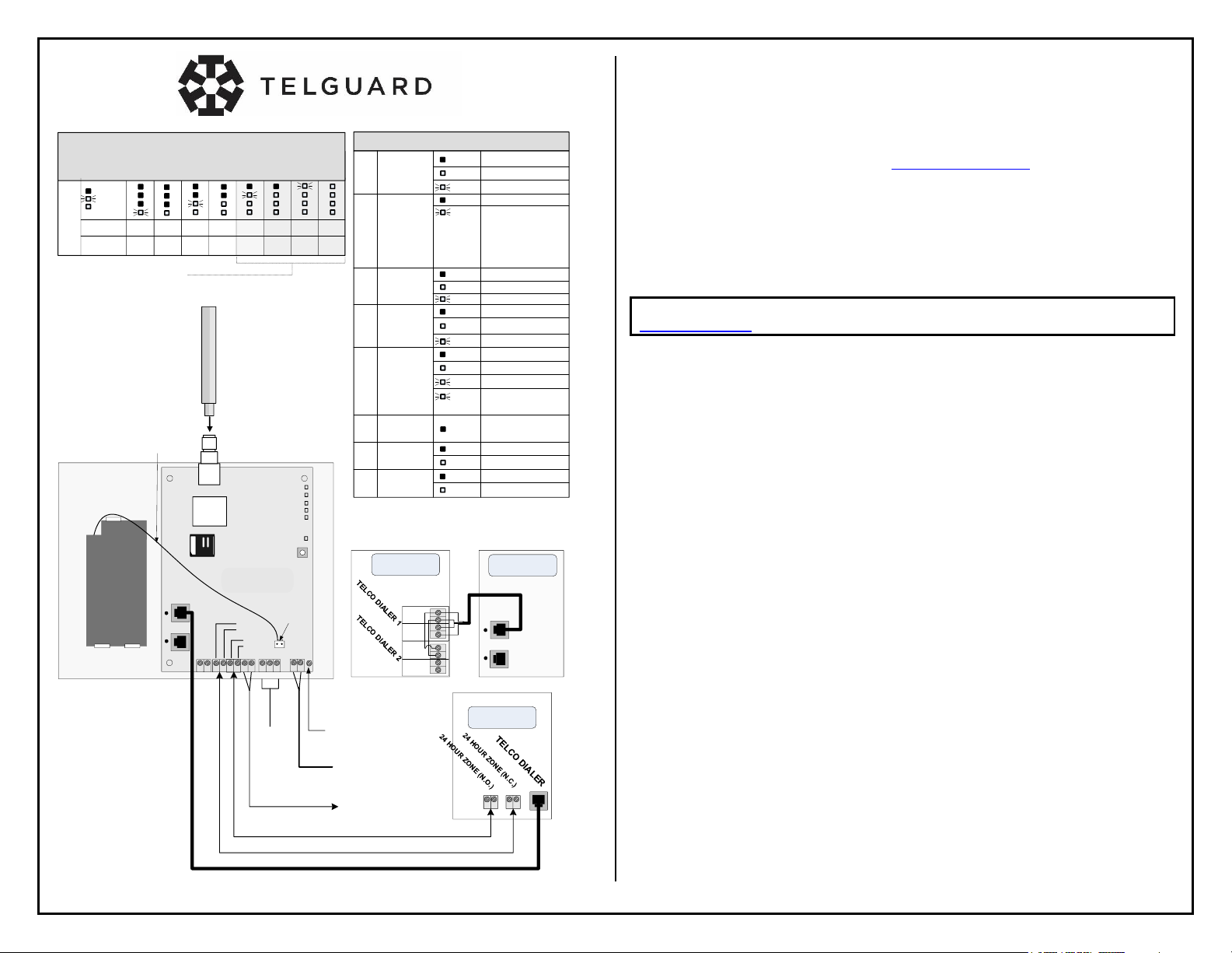
Telguard TG-7 Series
QUICK INSTALLATION GUIDE [SOLE PATH]
NOTE: If a TG-PEM Power and Expansion Module accessory is part of your installation, referto the full
Installation and Operation Guide available from www.telguard.com/7install.
Installation Summary
There are seven steps in installing Telguard properly. IF YOU DO NOT
PROCEED IN THE ORDER AND MANNER PRESCRIBED, YOU MAY NOT
COMPLETE THE INSTALLATION IN THE TIME ALLOCATED.
STEP 1: REGISTER FOR CELLULAR SERVICE
The registration form may be completed online through our 24/7 dealer portal
www.telguard.com.
STEP 2: LOCATE UNIT AND MEASURE SIGNAL STRENGTH (RSSI)
First, you will be confirming that Telguard has adequatecellular signalstrength. Press the LED/RSSI
Mode Toggle button one time, LEDs will now indicate signalstrength. Minimum recommended is 2.5
(2 on solid and the third flashing). Press the LED/RSSI Mode Toggle button a second time to exit
RSSI mode.
STEP 3: CONFIGURE ALARM PANEL FOR SOLE PATH CONNECTION
Fire panels are typically provided with two Telco connections. Becausethe TG-7 provides a single
connection, the panel must be set up accordingly. The first method of installationis toconfigurethe
panel to disable the second Telcoconnection. If this is not an option due to panel limitations, it is
possible tosplice both TIP and RING connections from the panel into the singlejack ofthe
Telguard. The TG-7 is capable of providing dial toneto both Telcoconnections.
STEP 4: PROGRAM,ACTIVATE &TRANSMIT PANEL ALARMS OVER THE
CELLULAR RADIO NETWORK
Program the TG-7 forSole Pathcommunication. You may do this by setting Memory Location 831
to a value of 3, using a butt-set. (See programming guide on reverse). LED 3 will be off when idle,
if successful. Next, connect the alarm panel's digital dialer output to Telguard and verify that alarm
signals can be reliably sent through Telguard over cellular to the central station digital receiver. A
minimum of two alarm signals must be transmitted. Activation is confirmed when LED 1 is
illuminated.
(NOTE: THE FIRST ALARM WILL ACTIVATE THE UNIT AT THE TELGUARD COMMUNICATION
CENTER,IT WILL NOT GO TO THE CENTRAL STATION,ALL SIGNALS AFTER THE FIRST ARE
SENT TO THE CENTRAL STATION)
STEP 5: CONNECT SUPERVISORY TRIP OUTPUTS
Next, you will wire Telguard's supervisory trip outputs to the alarm panel and then test.
STEP 6: CONNECT TRIP INPUT (OPTIONAL)
Optionally, you can wire an external relay input to the trip input lead and ground, and test.
STEP 7: COMPLETE THE INSTALLATION
Your last step will be to attach earth ground, and permanently mount the unit.
Other manuals for TG-7 Series
5
Popular Fire Alarm manuals by other brands


Notifier
Notifier VGM NION UniNet 2000 instruction manual

Hosiden Besson
Hosiden Besson Tri-Tone Sounder Installation details

Tyco
Tyco TIS-BG12LX manual

Autronica
Autronica BS-310 Operator's handbook

System Sensor
System Sensor PS12/24ADA Series Installation and maintenance instructions

Simplex
Simplex 4100-1314 installation instructions