NuAire XS User manual

XS-MFC Remote Switch Control
Designed to work in conjunction with the XS range of fans
and associated integral and remote sensors, the XS-MFC
Remote Switch Control offers the user the following:
a) On/Off.
b) Maximum or Economy performance.
c) Variable Speed Control.
d) Forward/Reverse airflow.
e) Auto/Manual operation.
Refer to the unit lift up lid for switch operating instructions.
The Remote Switch can control one fan or multiple fans,
depending on the fan and type of sensor being used.
Up to 5 fans (6 inch/9 inch) can be controlled by one XS-MFC.
Up to 2fans (size 12 inch) can be controlled by one XS-MFC.
Note: Do not mix fans of different sizes on the same control.
Siting position
Mount in a vertical plane with the grille at the bottom.
Mount the switch 1.5 metres from the floor (minimum).
Do not expose to excessive amounts of oil, grease or direct
water spray.
Do not subject switches to a direct heat source in excess
of 25oC.
Installation
Follow the pictorial sequence on this page.
Isolation - Before commencing work make sure
that the unit is electrically isolated from the mains supply.
13.04.23. Leaflet Number 671062
XS Fans Switches & Sensors
Remote Switch Control: XS-MFC
Integral Sensors: XS-PIR, XS-H, XS-AQ, XS-TH, XS-TA
Remote Sensors: XS-PIRR, XS-HR, XS-AQR
Installation Guide
The EMC Directive
2014/30/EU
The Low Voltage
Directive
2014/35/EU
1
Lift up panel and remove
two screws to dismantle
unit.
2
Push out backplate box
cable entry using a
screwdriver.
3
Spot through backplate
box and drill and plug
the wall. Fix backplate
box to the prepared wall.
4
Feed approx. 200mm of
supply cable into the box.
5
Connect the end of the
cable into the control
block. Connect wires as
shown in the appropriate
wiring diagram.
6
Hook lip of security
strap (if fitted) in hinge
socket. Fit the control
into the backplate box &
secure.
Test the installation.
200mm
Nuaire: A Trading Division of Polypipe Western Industrial Estate Caerphilly United Kingdom CF83 1NA
T: 029 2088 8911 E: [email protected] W: www.nuaire.co.uk
1

Isolation - Before commencing work make sure
that the unit is electrically isolated from the mains supply.
2
13.04.23. Leaflet Number 671062
Installation Guide XS Switches and Sensors
XS Integral Sensors
Designed to work in conjunction with and fit inside the XS
range of fans, the range of XS Integral Sensors offer the
user the following functions:-
XS-PIR
Passive Infra Red movement detector - senses body move-
ment, Run on Timer is adjustable between 2 and 40 minutes.
XS-H
Humidity Sensor - senses relative humidity. Adjustable
between 30% and 90% RH. Run on Timer is adjustable
between 2 and 40 minutes.
XS-AQ
Air Quality Sensor - detects odours and tobacco smoke.
Adjustable to suit size requirements. Run on Timer is adjustable
between 2 and 40 minutes.
XS-TH
Temperature Sensor - suitable for temperatures up to 25°C
(occasionally 35°C)
XS-TA
Run on Timer - adjustable between 2 and 40 minutes.
Siting
Mounted inside a fan.
Grille section adjacent to sensor must be changed to suit the
sensor being used (see fig 1).
Do not expose to excessive amounts of oil, grease or direct
water spray.
Do not subject sensors to a direct heat source in excess
of 25oC.
Installation
Follow the pictorial sequence on this page.
1
2
3
4
5
Push out the sensor
area cover from the
grille.
Remove the module plate.
Connect sensor to
fan using pre-wired
plug.
Screw the sensor
module into position
on the fan.
Fit new grille
insert into main
grille.

Isolation - Before commencing work make sure
that the unit is electrically isolated from the mains supply.
3
13.04.23. Leaflet Number 671062
Installation Guide XS Switches and Sensors
XS Remote Sensors
Designed to work in conjunction with the XS range of fans,
the range of XS Remote Sensors offer the user the following
functions:-
XS-PIRR
Passive Infra Red movement detector - senses body move-
ment, Run on Timer is adjustable between 2 and 40 minutes.
XS-HR
Humidity Sensor- senses relative humidity. Adjustable between
30% and 90% RH. Run on Timer is adjustable between 2 and
40 minutes.
XS-AQR
Air Quality Sensor- detects odours and tobacco smoke.
Adjustable to suit size requirements. Run on Timer is adjustable
between 2 and 40 minutes.
Note: Refer to the lift up lid for sensor operating
instructions.
Siting
Mount in a vertical plane.
The grille in sensor box should be at the bottom.
Mount the sensor 1.5 metres from the floor.
Do not expose to excessive amounts of oil, grease or direct
water spray.
Do not subject switches to a direct heat source in excess
of 25oC.
Installation
Follow the pictorial sequence on this page.
200mm
of cable
inside
box
1
2
3
4
5
1.5m
Remove screws
securing cover
to box.
Knock out cable entry
point and feed the
supply cable through
allowing approx.
200mm of cable to
protrude into box.
Drill & plug the
surface and fix the
back box to the wall.
If security strap
XS-SS is to be fitted:
Locate boss
centrally in slots.
Wire in the sensor
(see various wiring
options in the wiring
section),
Screw the sensor
module into position
on the wall. Hook lip
of security strap
(if fitted) in hinge
socket and secure
the boss using
the screw.

Isolation - Before commencing work make sure
that the unit is electrically isolated from the mains supply.
4
13.04.23. Leaflet Number 671062
Installation Guide XS Switches and Sensors
Electrical Wiring for One Fan

5
13.04.23. Leaflet Number 671062
Installation Guide XS Switches and Sensors
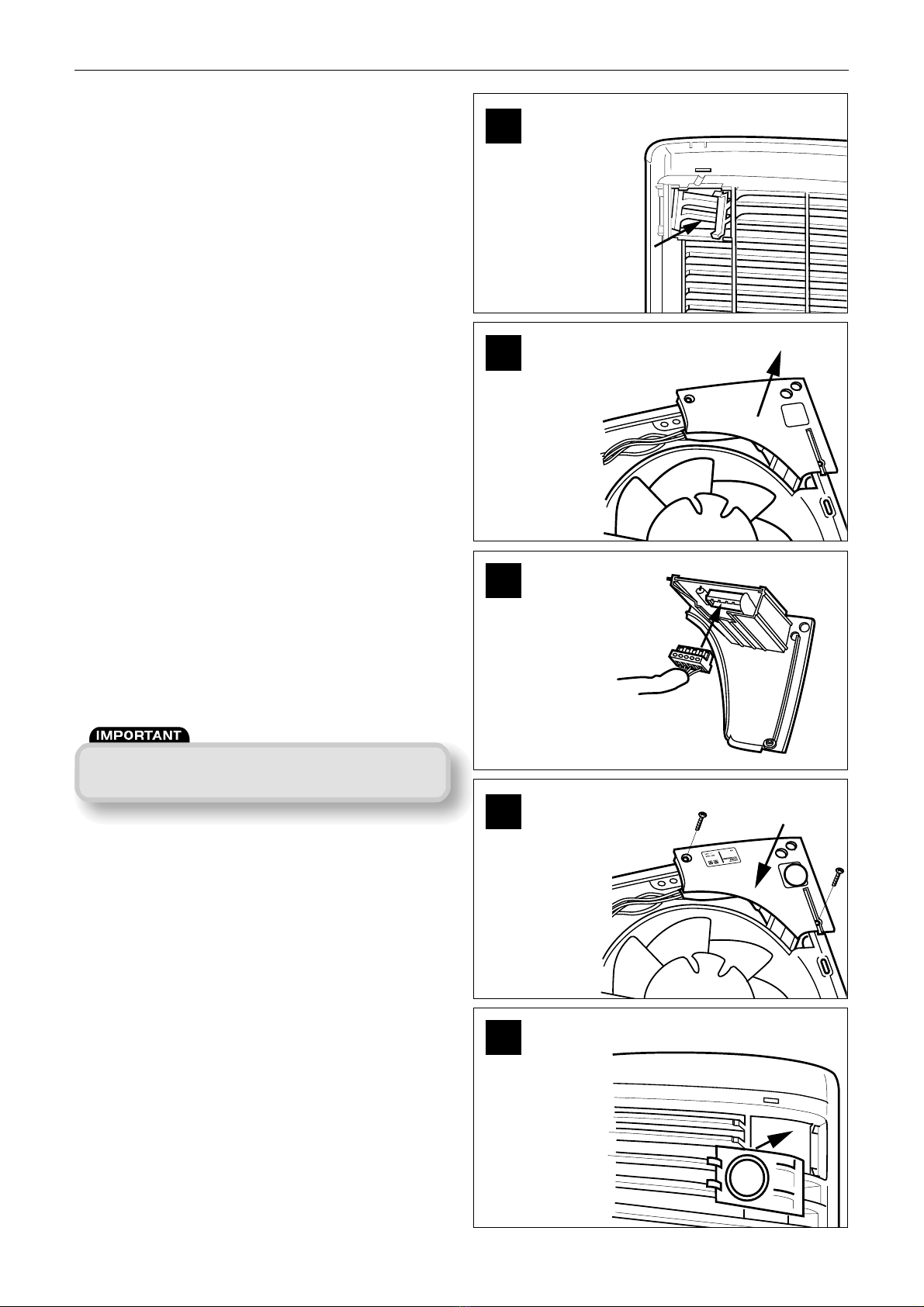
(Shutter Operation XS fans)
There will be a short delay on startup and shutdown of
approximately 40 seconds. This is normal.
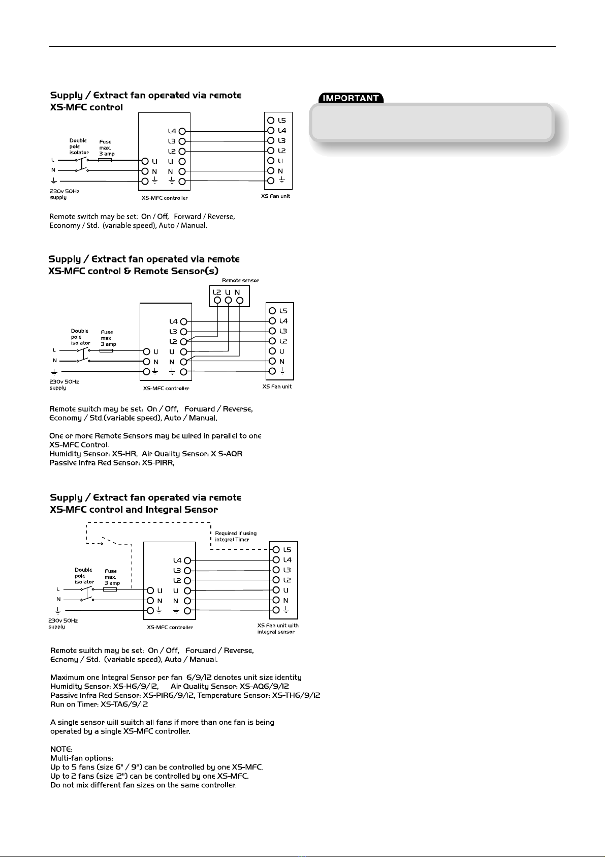
Wiring - Multiple Fans
Remote switch may be set:
On / Off, Forward / Reverse,
Economy / Std. (variable speed),
Auto / Manual.
Additional fans may be added
up to limit of control:
Up to 5 fans (size 6" / 9") can be
controlled by one XS-MFC.
Up to 2fans (size 12") can be
controlled by one XS-MFC.
Do not mix different fan sizes
on the same controller
XS-MFC controller
L5
L4
L3
L2
L1
N
L4
L3
L2
L1
N
L1
N
Double
pole
isolator
Fuse
max.
3 amp
L
N
XS Fan unit
230v 50Hz
supply
L5
L4
L3
L2
L1
N
XS Fan unit
L5
L4
L3
L2
L1
N
XS Fan unit
Multiple fans operated via remote XS-MFC control
XS-MFC controller
L5
L4
L3
L2
L1
N
L4
L3
L2
L1
N
L1
N
L
N
XS Fan unit
SENSOR
230v 50 H z
supply
L5
L4
L3
L2
L1
N
XS Fan unit
L2 L1 N
Remote switch may be set:
On / Off, Forward / Reverse,
Economy / Std. (variable speed),
Auto / Manual.
Additional fans may be added
up to limit of control:
Up to 5 fans (size 6" / 9") can be
controlled by one XS-MFC.
Up to 2fans (size 12") can be
controlled by one XS-MFC.
Do not mix different fan sizes
on the same contr.oller
L5
L4
L3
L2
L1
N
XS Fan unit
Double
pole
isolator
Fuse
max.
3 amp
Multiple fans operated via remote XS-MFC
control and a Remote Sensor
XS-MFC controller
(Required only when using Timer)
L5
L4
L3
L2
L1
N
L4
L3
L2
L1
N
L1
N
L
N
XS Fan unit
230v 50Hz
supply
L5
L4
L3
L2
L1
N
L5
L4
L3
L2
L1
N
Remote switch may be set:
On / Off, Forward / Reverse,
Economy / Std. (variable speed),
Auto / Manual.
Multiple fans operated via remote
XS-MFC control and one
Integral Sensor in Fan 1
Additional fans may be added
up to limit of control:
Up to 5 fans (size 6" / 9") can be
controlled by one XS-MFC.
Up to 2fans (size 12") can be
controlled by one XS-MFC.
Do not mix different fan sizes
on the same controller.
Double
pole
isolator
Fuse
max.
3 amp
XS Fan unit
XS Fan unit
Fan unit
(fitted with
integral
sensor)
Multiple fans operated via remote XS-MFC control and
one Integral Sensor in Fan 1
Remote switch may be set:
On / Off, Forward / Reverse,
Economy / Std. (variable speed),
Auto / Manual.
XS-MFC controller
SENSOR1
L5
L4
L3
L2
L1
N
L4
L3
L2
L1
N
L1
N
L
N
XS Fan unit
230v 50Hz
supply
L2 L1 N
SENSOR 2
L2 L1 N
Double
pole
isolator
Fuse
max.
3 amp
Fan operated using remote XS-MFC control
and a Multiple Remote Sensor
Note:
Note: If 2 x 12 nch fans or 3 x 6 or 9 nch fans are used n the
same operat ng mode n the same room they should all be
controlled from the same MFC speed control. Th s avo ds the
poss b l ty of one fan ( f speed controlled at a lower flow rate)
be ng stalled by the other fan(s).
Adequate make-up a r prov s on suff c ent to prov de vent lat on n
accordance w th bu ld ng regulat ons s requ red n all rooms. Th s
should be checked dur ng comm ss on ng w th all fans n the same
room runn ng together n all poss ble conf gurat ons.
The automat c shutters, motor bear ngs should be frequently
nspected and ma nta ned to ensure they open fully/operate
sat sfactor ly. Use of an RCD and fused spur w th 1A, Bussmann
TDC180, BS1362, fuse (Farnell order no: 1123029) for 1 fan or 2A,
Bussmann TDC180, BS1362 fuse (Farnell order no: 1123032) for 2
or 3 fans s recommended.
Always conf rm a rflow d rect on before comm ss on ng.
This manual suits for next models
9
Table of contents
Other NuAire Switch manuals
Popular Switch manuals by other brands

SMC Networks
SMC Networks SMC6224M Technical specifications

Aeotec
Aeotec ZWA003-S operating manual

TRENDnet
TRENDnet TK-209i Quick installation guide

Planet
Planet FGSW-2022VHP user manual

Avocent
Avocent AutoView 2000 AV2000BC AV2000BC Installer/user guide

Moxa Technologies
Moxa Technologies PT-7728 Series user manual

Intos Electronic
Intos Electronic inLine 35392I operating instructions

Cisco
Cisco Catalyst 3560-X-24T Technical specifications

Asante
Asante IntraCore IC3648 Specifications

Siemens
Siemens SIRIUS 3SE7310-1AE Series Original operating instructions

Edge-Core
Edge-Core DCS520 quick start guide

RGBLE
RGBLE S00203 user manual