Telsey Telecommunications MARTY User manual

USER MANUAL: MARTY
RESIDENTIAL ACCESS GATEWAY
THE MOST COMPLETE OFFER
MTMGCMRSIEN10
telecommunications

Installation Guide Marty W-Gate
2

Marty W-Gate Installation Guide
3
Index
1. PACKAGE CONTENT ..................................................................................................5
2. INTRODUCTION .......................................................................................................5
3. SAFETY INFORMATION ............................................................................................5
4. GENERAL ADVERTISEMENT......................................................................................6
5. ENVIRONMENTAL CONDITIONS ..............................................................................7
6. CONFORMITY DECLARATION...................................................................................7
7. FUNCTIONAL FEATURES...........................................................................................9
7.1. TECHNICAL FEATURES .................................................................................................................9
8. MARTY W-GATE FRONT AND BACK PANEL DESCRIPTION ....................................10
8.1. FRONT PANEL .........................................................................................................................10
LED description ..............................................................................................................................10
8.2. BACK PANEL ...........................................................................................................................11
Interfaces, Switch and Supply connector ..........................................................................................11
8.3. LATERAL SIDE .........................................................................................................................11
Smart Card side (for future use) and Reg switc (for future use).........................................................11
9. MARTY W-GATE PLACEMENT .................................................................................11
9.1. PLACEMENT ON A SURFACE .........................................................................................................12
9.2. WALL-MOUNTABLE PLACEMENT ....................................................................................................12
10. MARTY W-GATE INSTALLATION ............................................................................13
10.1. CONNECT THE MARTY W-GATE WITH THE POWER SUPPLY...................................................................13
10.2. ADSL ACTIVATION ...................................................................................................................13
11. COMPUTER CONNECTION ......................................................................................14
11.1. ETHERNET CONNECTION ............................................................................................................14
11.2. USB CONNECTION....................................................................................................................15
11.3. WI-FICONNECTION .................................................................................................................16
11.4. LOCAL AND INTERNET CONNECTION ..............................................................................................16
12. MINIMUM COMPUTER REQUIREMENTS.................................................................17
13. MARTY W-GATE CONFIGURATION.........................................................................18
13.1. WEB USER INTERFACE ..............................................................................................................18
13.2. QUICK SETUP .........................................................................................................................19
THE ISP is included in the list ..........................................................................................................19
THE ISP is NOT included in the list...................................................................................................21
13.3. DETAILED SETUP .....................................................................................................................25
14. TROUBLESHOOTING...............................................................................................26

Installation Guide Marty W-Gate
4
Marty W-Gate Installation Guide
5
1
1.
.P
Pa
ac
ck
ka
ag
ge
ec
co
on
nt
te
en
nt
t
The package includes the following devices:
x1 modem ADSL/ADSL2+
x1 power supply (240 Vac 50 Hz/12 Vdc 1200 mA, switching type)
x1 CD-ROM
x1 Installation and user guide
x1 RJ11 phone cable (length= 180 cm)
x1 RJ ADSL FILTER
x2 Ethernet cables UTP cat. 5 straight (length= 180 cm)
x1 USB cable (length= 100 cm)
x1 wall-mountable kit
2
2.
.I
In
nt
tr
ro
od
du
uc
ct
ti
io
on
n
This manual contains the information for the Marty W-Gate appropriate use. It contains also the installation
rules that have to be followed for the safety of the users and the correct use of the Marty W-Gate.
Meaning of the symbols:
It notifies important instructions regarding device installation and use.
It notifies the dangerous of electrical shock caused by not electrical isolation inside the
device.
This guide informs about the connection of the Marty W-Gate with other devices (computer, phone etc...)
and relative configurations in order to have the Internet connection in few minutes.
3
3.
.S
Sa
af
fe
et
ty
yi
in
nf
fo
or
rm
ma
at
ti
io
on
n
Warning: Do not work on equipments or cables during periods of lightning activity.
Warning: To prevent electric shock, do not remove the cover. No user-serviceable part inside. This
unit contains hazardous voltages and should only be opened by a trained and qualifies technician.
To avoid the possibility of electric shock, disconnect electric power to the product before
connecting or disconnecting the LAN cables. Power cord is used as a disconnection device. To de-energize
equipment, disconnect the power cord.
Do not connect more than the recommended amount of wire. Stripping more than the
recommended amount can create a safety hazard by leaving exposed wire on the terminal block
after installation
When installing this equipment, always ensure that the frame ground connection is installed first
and disconnected last. The power source for the router should be located near the unit and should
be easily accessible.
Check to see if there are any exposed copper strands coming from the installed wire. When this
installation is done correctly there should be no exposed copper wire strands extending from the
terminal block. Any exposed wiring can conduct harmful levels of electricity to persons touching

Installation Guide Marty W-Gate
6
the wires.
Warning: Only trained and qualified personnel are allowed to install or to replace this equipment.
Warning: To reduce risk of fire use only 18 AWG or larger wires, that should be provided by the
installer.
Warning: When using your Communication equipment, basic safety precautions should always be
followed to reduce the risk of fire, electronic shock, and injury to persons, including the following:
• Do not use this product near water, for example, near a bathtub, washbowl, kitchen sink, or
laundry tub in a wet basement or near a swimming pool.
• Avoid using a Communication equipment (other than a cordless type) during electrical storm. There may
be a remote risk of electric shock from lightning.
• Do not use the Communication equipment to report a gas leak in the vicinity of the leak.
Warning: To redue the risk of fire, use only 26 AWG or larger telecommunication line cords.
4
4.
.G
Ge
en
ne
er
ra
al
lA
Ad
dv
ve
er
rt
ti
is
se
em
me
en
nt
t
Don't damage the warranty label: if the warranty label is not intact the warranty conditions are not
valid.
Don't place the device on unsteady positions.
Caution: Air vents must not be blocked and must have free access to the room ambient air for
cooling. To allow proper cooling of the device, make sure that the air flow around the unit and
through its heat sink cooling fins on the base is not restricted.
Warning: Operating Temperature. This product is designed for a maximum ambient temperature of 35°
degrees C.
If the device is installed indoors, make sure that the site is a dust-free environment. The site should
provide for easy access to the ports of the gateway device. This will make it easy for you to connect
and disconnect cables, as well as view the LEDs.
Circuit Overloading: Consideration should be given to the connection of the equipment to the
supply circuit and the effect that overloading of circuits might have on overcurrent protection and
supply wiring.
Appropriate consideration of equipment nameplate ratings should be used when addressing this concern.
Warning: For centralized AC power connection, install only in a restricted access area.
Do not install in direct sunlight, or a damp or dusty place. Do not expose the device to
moisture or water.
Avoid long exposition of the human body to the Wi-Fi devices. Install the Wi-Fi devices at a
distance not inferior of 20 cm from the users.
WEEE DISPOSAL OF WASTE EQUIPMENT IN THE EUROPEAN
UNION
This symbol on the product or on its packaging indicates that this product must not be
disposed of with your other household waste. Instead, it is your responsibility to dispose
of your waste equipment by handing it over to a designated collection point for the
recycling of waste electrical and electronic equipment. The separate collection and
recycling of your waste equipment at the time of disposal will help to conserve natural resources and ensure
that it is recycled in a manner that protects human health and the environment. For more information about
where you can drop off your waste equipment for recycling, please contact your local city office, your
household waste disposal service or the shop where you purchased the product. For equipment used for
professional use, please contact your supplier to verify terms and conditions of the purchase contract. These
products must be disposed off separately from the other waste.

Marty W-Gate Installation Guide
7
5
5.
.E
En
nv
vi
ir
ro
on
nm
me
en
nt
ta
al
lC
Co
on
nd
di
it
ti
io
on
ns
s
Use the Marty W-Gate in these environmental conditions:
Storage Temperature: from -20 to 65 °C
Operating Temperature: from 0 to 35 °C
Humidity: 5% - 85% (without moisture)
6
6.
.C
Co
on
nf
fo
or
rm
mi
it
ty
yD
De
ec
cl
la
ar
ra
at
ti
io
on
n
This equipment is in compliance with the essential requirements and other relevant provisions of Directive
1999/5/EC.
We inform you that the use of the mentioned device is subject to:
1) D.Lgs 1.8.2003, n.259, paragraphs 104 (general authorization subjected activities) and 105 (free use), for
private use;
2) D.M. 28.5.03 and following modifications, for R-LAN access to networks and to telecommunication
services will be provided to the public.
Note: The full declaration of conformity for this product can be requested directly to Telsey
The following standards has been applied during the assessment of the product according to the
requirements of the Directive1999/5/EC:
Applied Standards
ETSI EN301 489-17:V1.2.1
ETSI EN301 489-01:V1.4.1
EN55022:1998 +A1:2000 +A2:2003
DT/El2 R10
EN55024:1998 +A1:2000 +A2:2003
EN61000-3-3:1995 +A1:2001
EN61000-4-2:1995 +A1:1998 +A2:2001
EN61000-4-3:1995 +A1:1998 +A2:2001
EN61000-4-4:1995 +A1:2001 +A2:2001
EN61000-4-5:1995 +A1:2001
EN61000-4-6:1996 +A1:2001
EN61000-4-11:1994 +A1:2001
EN60950-1:2001
EN 300 328
ITU-T K21
State Members in EU with restrictions
National Restrictions
In most of the EU and other European countries, the 2.4- and 5-GHz bands have been made available for the use of
wireless LANs. The following table provides an overview of the regulatory requirements which are generally applicable
for the 2.4- and 5-GHz bands.
In the last part of this section you will find an overview of the countries in which additional restrictions or requirements
or both are applicable.
The requirements for any country may evolve. Telsey recommends you to check with local authorities for the latest
status of their national regulations for both 2.4- and 5-GHz wireless LANs.

Installation Guide Marty W-Gate
8
This product may be used in all EU countries (and all the other countries following the EU directive 1999/5/EC) without
any limitation except for the countries mentioned below:
Ce produit peut être utilisé dans tous les pays de l'UE (et dans tous les pays ayant transposés la directive 1999/5/CE)
sans aucune limitation, excepté pour les pays mentionnés ci-dessous:
Questo prodotto è utilizzabile in tutte i paesi EU (ed in tutti gli altri paesi che seguono le direttive EU 1999/5/EC) senza
nessuna limitazione, eccetto per i paesii menzionati di seguito:
Das Produkt kann in allen EU Staaten ohne Einschränkungen eingesetzt werden (sowie in anderen Staaten die der EU
Direktive 1995/5/CE folgen) mit Außnahme der folgenden aufgeführten Staaten:
Austria and Switzerland
The use of the band from 5470 to 5725 MHz is not allowed in Austria or Switzerland.
Die Verwendung des Frequenzbereichs von 5470 MHz bis 5725 MHz ist in Österreich und Schweiz nicht zulässing.
L’utilisation de la bande 5470 à 5725 MHz n’est pas autorisée en Autriche at en Suisse.
L’uso della banda compresa fra 5470 MHz e 5725 MHz non è permesso in Austria e Svizzera.
Belgium
Outdoor wireless links with a range in excess of 300 meters need to be notified at the Belgian Institute for Postal
Services and Telecommunications (BIPT). Please visit http://www.bipt.be for more details.
Draadloze verbindingen voor buitengebruik en met een reikwijdte van meer dan 300 meter dienen aangemeld te worden
bij het Belgisch Instituut voor postdiensten en telecommunicatie (BIPT). Zie http://www.bipt.be voor meer gegevens.
Les liaisons sans fil pour une utilisation en extérieur d'une distance supérieure à 300 mètres doivent être notifiées à
l'Institut Belge des services Postaux et des Télécommunications (IPBT). Visitez http://www.ibpt.be pour de plus amples
détails.
Tab.: Regulatory Requirements for Wireless LANs
France
The use of the band from 5470 to 5725 MHz is not allowed in France. The band from 5150 to 5350 MHz can only be
used indoors. In case the product is used outdoors, the usage of any 5-GHz frequency is not allowed, but for 2.4-GHz,
the output power is restricted in some parts of the 2.4-GHz band. See following table or visiting http://www.art-
telecom.fr for more details.
L’utilisation de la bande 5470 à 5725 MHz n’est pas autorisée en France. La bande de 5150 à 5350 MHz ne peut être
utilisée qu’à l’intérieur d’un bâtiment. Dans le cas ‘une utilisation en extérieur aucune fréquence dans le bandes des 5
GHz n’est permise, tandis que la puissance est limitée dans certaines parties de la bande des 2.4 GHz.
Voir la table ci-dessous ou visitez http://www.art-telecom.fr pour de plus détails.
Tab. 4: Applicable Power Levels for 2.4-GHz and 5-GHz in France (Puissances utilsables dans les bendes
2.4-GHz et 5-GHz en France)
Italy
This product meets the National Radio Interface and the requirements specified in the National Frequency Allocation
Table for Italy. It can be installed without authorization within the boundaries of the owner's property as defined on
D.Lgs 1.8.2003, article 104 (activities subject to general authorization) and 105 (free use). For public services of Wireless
LAN access, it requires a general authorization as defined on DM 28.05.03 “Wi-fi service regualmentation for public use”.
Please check with http:// www.comunicazioni.it/ for more details.
Questo prodotto è conforme alla specifiche di Interfaccia Radio Nazionali e rispetta il Piano Nazionale di ripartizione delle

Marty W-Gate Installation Guide
9
frequenze in Italia.Esso può essere istallato senza alcuna autorizzazione all’interno di un fondo o al di fuori del proprio
fondo per uso privato ai sensi del D.Lgs 1.8.2003 articoli 104 (attività soggette ad autorizzazione generale) e 105 (libero
uso). Per la fornitura la pubblico dell’accesso Wireless LAN, richiede una "Autorizzazione Generale" ai sensi del Decreto
ministeriale 28 maggio 2003 “Regolamentazione dei servizi Wi-fi ad uso pubblico”. Consultare
http://www.comunicazioni.it per maggiori dettagli.
Norway
This product meets the National Radio Interface and the requirements specified in the National Frequency Allocation
Table for Norway. Use of the frequency band 2400 - 2483.5 MHz is authorised in accordance with the frequency use
defined in the standard ETS 300 328. This subsection does not apply for the geographical area with a radius of 20 km
from the centre of NyÅlesund. Indoor use of the frequency band 5150 - 5350 MHz (Frequency Band A) is authorised for
local radio networks. Use of the frequency band 5470 - 5725 MHz (Frequency Band B) is authorised for local radio
networks. For more information please visit:
http://www.npt.no/portal/page?_pageid=118,45999&_dad=portal&_schema=PORTAL.
Ireland
Provision of services to the public is permitted. Public service provider is required to hold an appropriate
Telecommunications License (ref. ODTR 98/44R). For more information please visit: http://www.odtr.ie
External Antennas and Power Levels
Telsey’s 2.4-GHz wireless products have two external (dedicated) antennas of 2dBi gain and the output power of the
equipment result in a maximum radiated power less than 100 mW EIRP.
Use only the Ethernet cable included in the package or cables with the same feature (UTP
cat. 5 not screen), in order to respect the European Directive 89/336 Class B for electromagnetic
compatibility in residential environment.
7
7.
.F
Fu
un
nc
ct
ti
io
on
na
al
lF
Fe
ea
at
tu
ur
re
es
s
Marty W-Gate allows Broadband Network Operators to easily connect residential customers to their
ADSL2+/ADSL2/ADSL networks and combines traditional Ethernet 10/100 BaseTX and USB interfaces for the
home LAN with an IEEE 802.11b/g wireless access point. Marty W-Gate is intended for the efficient delivery
of Fast Internet and Voice over IP services. The support of the integrated VoIP interfaces (2 FXS ports) is
provided as an optional module that can be also installed by the end user. This allows operators to invest on
VoIP services when and only when it will launch the service, pursuing efficient "pay as you grow" strategy.
7
7.
.1
1.
.T
Te
ec
ch
hn
ni
ic
ca
al
lF
Fe
ea
at
tu
ur
re
es
s
Standard ADSL:
ITU G.992.1/2/3/5 Annex A
ANSI T1.413.
Supported Protocols:
RFC 2516 (PPP over Ethernet)
RFC 2684 / formerly RFC 1483 e RFC 2364 (PPPoA)
ATM UNI3.1, UNI4.0 support
IPTV functionality by port mapping
OAM F4/F5 Loop-back
ADSL Interface, RJ11 connector
USB full speed interface (12 Mbps), type B connector, “Universal Serial Bus Specification” rev.1.1
standard compatible
Ethernet interface, RJ45 connector, IEEE 802.3 10/100 Base-T auto sensing standard compatible
Ethernet/SetTopBox interface, RJ45 connector, IEEE 802.3 10/100 Base-T auto sensing standard
compatible
Wi-Fi IEEE 802.11b/g interface1
Speed Transmission: 11/54 Mbps
Encryption key:
WPA with 24 ASCII characters Pass-phrase (256 bit WPA-PSK key)
WEP with 128 bit (13 ASCII characters)
WiSeConf support (TM)
1The Wi-Fi is a trade mark registred on Wi-Fi Alliance.
Installation Guide Marty W-Gate
10
WPA2
WPA-PSK
DHCP server
NAPT, Virtual Server and ALG
Web User Interface for local configuration and management
SNMP v3 Protocol for remote configuration and management
Firmware upgrade
8
8.
.M
Ma
ar
rt
ty
yW
W-
-G
Ga
at
te
eF
Fr
ro
on
nt
ta
an
nd
db
ba
ac
ck
kP
Pa
an
ne
el
lD
De
es
sc
cr
ri
ip
pt
ti
io
on
n
8
8.
.1
1.
.F
Fr
ro
on
nt
tP
Pa
an
ne
el
l
L
LE
ED
Dd
de
es
sc
cr
ri
ip
pt
ti
io
on
n
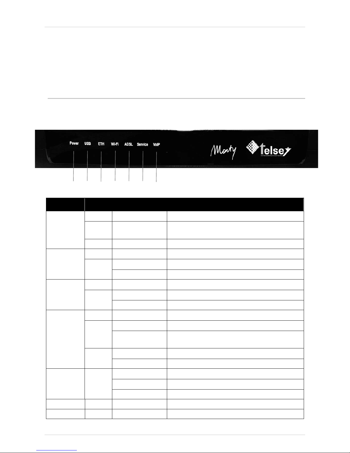
LED Colour Mode Meaning
- OFF The device is off
RED ON Malfunction on device, see the Troubleshooting
chapter on this manual.
Power
GREEN ON The device is on
- OFF USB connection not established
ON USB connection established
USB
GREEN
BLINKING USB traffic in progress
- OFF Ethernet connection not established
ON Ethernet connection established
ETH
GREEN
BLINKING Ethernet traffic in progress
- OFF Wi-Fi disabled
ON Wi-Fi enabledRED
LOW BLINKING Wi-Fi WiSeConf (TM)®devices registration in progress
ON Wi-Fi connection
Wi-Fi
GREEN
SPEED BLINKING Wi-Fi connection and traffic in progress
ON ADSL connection
LOW BLINKING ADSL connection in progress (activation phase)
ADSL GREEN
SPEED BLINKING ADSL connection in progress (activation phase)
Service For future use
VoIP - For future use
POWER USB ETH WI-FI ADSL Service VoIP
Marty W-Gate Installation Guide
11
In the activation phase all the leds are green on until the end of auto diagnostic phase.
In case of malfunction, only the led POWER is red on, while all the other leds are off.
8
8.
.2
2.
.B
Ba
ac
ck
kP
Pa
an
ne
el
l
I
In
nt
te
er
rf
fa
ac
ce
es
s,
,S
Sw
wi
it
tc
ch
ha
an
nd
dS
Su
up
pp
pl
ly
yc
co
on
nn
ne
ec
ct
to
or
r
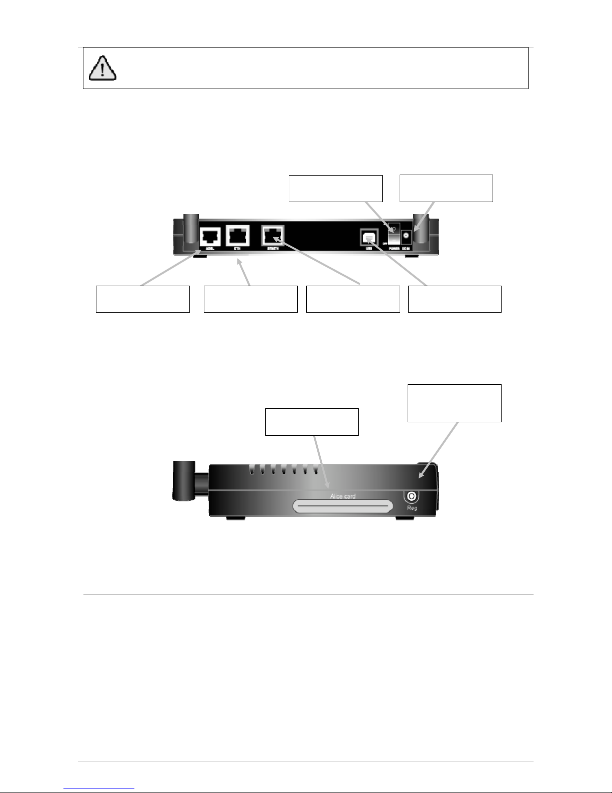
8
8.
.3
3.
.L
La
at
te
er
ra
al
ls
si
id
de
e
S
Sm
ma
ar
rt
tC
Ca
ar
rd
ds
si
id
de
e(
(f
fo
or
rf
fu
ut
tu
ur
re
eu
us
se
e)
)a
an
nd
dR
Re
eg
gs
sw
wi
it
tc
c(
(f
fo
or
rf
fu
ut
tu
ur
re
eu
us
se
e)
)
9
9.
.M
Ma
ar
rt
ty
yW
W-
-G
Ga
at
te
ep
pl
la
ac
ce
em
me
en
nt
t
The correct placement of Marty W-Gate permits a full speed performance.
To find the optimal placement of the Marty W-Gate it is necessary to consider some conditions that have to
be compatible with your placement needs in the domestic network. Indeed, in typical conditions, the sphere
of Wi-Fi action is more than 10 meters and in order to obtain the Wi-Fi cover optimization is necessary to
respect the following requirements:
1. If possible, give preference to a central position of the Marty W-Gate respect the house planimetry.
2. The Marty W-Gate and other Wi-Fi devices connected to it have not to be placed inside closed
drawers or anyway, have to be positioned where they are not screened by metal surfaces and/or
wall pillars.
3. Don't place the Marty W-Gate where could be present obstacles between it and other Wi-Fi devices.
POWER
CONNECTOR
POWER SWITCH
ADSL INTERFACE STB/Ethernet
INTERFACE
USB INTERFACE
ETHERNET
INTERFACE
REG
Smart Card side

Installation Guide Marty W-Gate
12
4. If possible, place the Marty W-Gate on at least 1 meter altitude and in any case in an inferior
position respect to the doors height.
5. Place the Marty W-Gate distant to devices that work on the same frequency (for example: television,
receiver etc...) or devices that produce electromagnetic field (for example: TV, microwaves etc...).
6. Place the antennas in vertical position, on the direction of the Wi-Fi devices that have to be
connected, avoid inserting metal objects.
Proceed with the Marty W-Gate placement, positioning it on a surface or fixing it on wall (see also chapter 3
“General Advertisement” and chapter 4 “Environmental Conditions” on this guide)
9
9.
.1
1.
.P
Pl
la
ac
ce
em
me
en
nt
to
on
na
as
su
ur
rf
fa
ac
ce
e
For the placement on a surface it is only necessary to lay the Marty W-Gate on a surface and place the
antennas in vertical position.
9
9.
.2
2.
.W
Wa
al
ll
l-
-m
mo
ou
un
nt
ta
ab
bl
le
ep
pl
la
ac
ce
em
me
en
nt
t
In case of wall-mountable placement, proceed as following:
xtake the wall-mountable kit included in the package
xfix the plastic anchors, using the reference carton shape holes as guide (the carton shape holes is
included in the package)
xscrew the screws on the plastic anchors
xfasten the Marty W-Gate on the screws, doing a movement as described on the above draw
xplace the antennas in vertical position

Marty W-Gate Installation Guide
13
1
10
0.
.M
Ma
ar
rt
ty
yW
W-
-G
Ga
at
te
ei
in
ns
st
ta
al
ll
la
at
ti
io
on
n
1
10
0.
.1
1.
.C
Co
on
nn
ne
ec
ct
tt
th
he
eM
Ma
ar
rt
ty
yW
W-
-G
Ga
at
te
ew
wi
it
th
ht
th
he
eP
Po
ow
we
er
rS
Su
up
pp
pl
ly
y
Take the power supply included in the package and proceed as following described:
xinsert the power supply plug on the power socket
xinsert the power supply connector on the power connector situated on the back of Marty W-Gate
xTurn on the Marty W-Gate pushing the POWER switch situated on the back of it.
xCheck that the POWER led situated on the front of Marty W-Gate is green on (see the LED
description table in chapter 7 of this manual for further information about the led meanings).
1
10
0.
.2
2.
.A
AD
DS
SL
La
ac
ct
ti
iv
va
at
ti
io
on
n
Connect the Marty W-Gate to the ADSL line using the telephone cable (RJ11) included in the package or, in
case there is also a phone device in the same socket, use an ADSL filter to make the connection.
In this last case, take the telephone cable and the ADSL filter included in the package and proceed as
following described:
xinsert the telephone cable on the ADSL connector in the back of Marty W-Gate
xdisconnect the telephone device RJ socket from the wall socket
xinsert the ADSL RJ filter between the wall socket and the telephone device RJ socket
xinsert the Marty W-Gate telephone cable to the ADSL filter socket indicated with the word “MODEM”.
Passive installation can be different from country to country. For the proper connection of the device please
contact your local operator.
POWER SWITCH
Power Supply
A
DSL filter

Installation Guide Marty W-Gate
14
To be sure that the Marty W-Gate and telephone device work correctly it is necessary to insert an ADSL filter
on every telephone sockets with telephone device present in the telephone plant.
Verify if the ADSL connection is present, checking the ADSL led situated in the front panel of Marty W-Gate:
if the ADSL led is green on the ADSL connection is present, if the led is blinking means that the connection
with ADSL line is not concluded; wait until the ADSL led will be green on.
Every time that the Marty W-Gate is turned on, it is necessary to wait until the POWER and
ADSL leds become green.
If your telephone plant has not the RJ11 socket, contact your Internet Service Provider for the installation.
Proceed with the connection of computers as described in the following chapter.
1
11
1.
.C
Co
om
mp
pu
ut
te
er
rc
co
on
nn
ne
ec
ct
ti
io
on
n
More computers can be connected to the Marty W-Gate using different connections (Ethernet, USB and Wi-
Fi). If the computer that has to be connected to the Marty W-Gate has both the Ethernet interface and USB
interface is recommend to use the Ethernet connection; in this case the USB connector is free for the
connection of further USB devices (webcam, scanner, etc...).
Each computer can be connected to Marty W-Gate using only one interface on the
computer.
Before connecting the computer, it is recommend to uninstall drivers of other ADSL
modem previously installed. Following the instruction of the computer supplier for
the procedure.
1
11
1.
.1
1.
.E
Et
th
he
er
rn
ne
et
tC
Co
on
nn
ne
ec
ct
ti
io
on
n
Proceed as following :
xtake the Ethernet cable included in the package
xconnect the Ethernet cable to the Ethernet connector situated on the back of Marty W-Gate (it is
possible to use both the “ETH” and “ETH/STB” interfaces).
xconnect the other plug Ethernet cable to the Ethernet connector of the computer

Marty W-Gate Installation Guide
15
1
11
1.
.2
2.
.U
US
SB
Bc
co
on
nn
ne
ec
ct
ti
io
on
n
In order to limit USB malfunctions it is recommend to avoid:
xpassive hub USB, devices that allow to connect more USB devices (webcam, printer, scanner etc..)
to a only computer port.
xrepeat USB port on keyboards and further devices.
xadditional USB board (PCI o ISA boards that allow to add one or more USB port on the
computer).
The devices above described could produce a malfunction of Marty W-Gate USB interface.
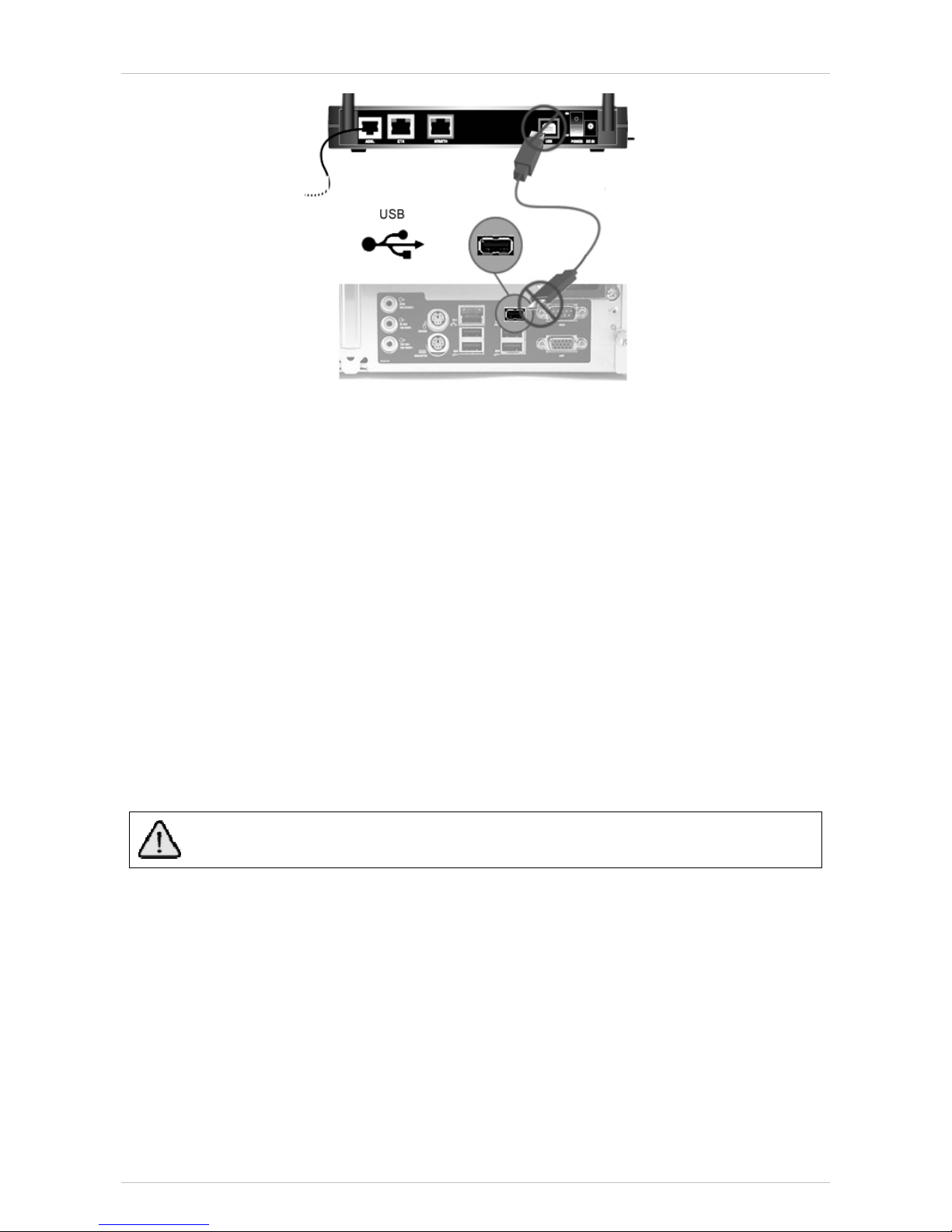
In order to connect the computer by the USB interface it is necessary to install the Marty W-Gate drivers in
the computer.
xinsert the CD-Rom included in the package on the computer CD-ROM reader.
xSelect "Computer Resourses" by clicking on the icon on the PC desktop.
xif present, remove the security label or cap on the USB port of Marty W-Gate
xtake the USB cable included in the package
xconnect the USB cable to the USB connector of the Marty W-Gate
xconnect the other plug of USB cable to the USB connector of the computer
xFollow the Windows instruction for USB device connection that appears on the screen by clicking on
“set the driver’s path”. Select the Cartel inside the CD-Rom where the Marty W-Gate driver is
contained.
Installation Guide Marty W-Gate
16
1
11
1.
.3
3.
.W
Wi
i-
-F
Fi
iC
Co
on
nn
ne
ec
ct
ti
io
on
n
In order to connect the computer using the Wi-Fi connection it is necessary to configure the Marty W-Gate.
See chapter 12 “Marty W- Gate Configuration” for more information.
If the Marty W-Gate configuration has already been made, in order to connect your computer using the
Wireless network, looking for the Wi-Fi devices available, select the name of the Marty W-Gate SSID
(assigned during the configuration), and field the encryption key password. For further information see
“Marty W-Gate Configuration” chapter on this manual.
1
11
1.
.4
4.
.L
Lo
oc
ca
al
la
an
nd
dI
In
nt
te
er
rn
ne
et
tc
co
on
nn
ne
ec
ct
ti
io
on
n
When the computer is connected to the Marty W-Gate, it is ready to:
xlocal connection to the Marty W-Gate Web User Interface (necessary to check and change the Marty
W-Gate configuration). See chapter 12 “Marty W-Gate Configuration”.
xthe Internet connection (be sure to have the ADSL connection by checking that the ADSL led is
green on). Internet connection will be available only if the Marty W-Gate has been configured (see
chapter 12 “Marty W-Gate Configuration”).
For surfing in the Internet is necessary that the POWER and ADSL leds are green. If the ADSL
led is blinking, wait that the ADSL connection is establish.
Marty W-Gate Installation Guide
17
1
12
2.
.M
Mi
in
ni
im
mu
um
mc
co
om
mp
pu
ut
te
er
rr
re
eq
qu
ui
ir
re
em
me
en
nt
ts
s
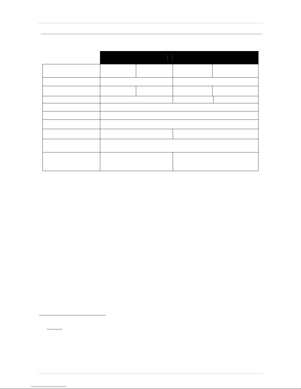
The computer has to have the following requirements in order to be connected to the Marty W-Gate:
PC Intel®compatible Apple®Mac
Operating System Windows®
98SE/ME
Windows®
2000/XP
MacOS®
9.1
MacOS®
10.1
Processor Pentium®500MHz PowerPC®
RAM 32 MB 64 MB 32 MB2128 MB
Free space on Hard Disk 185MB 40MB 10MB
CD or DVD reader present
Video Board 800x600 pixel, 256 colours
Ethernet 10/100baseT Necessary for the Ethernet connection
USB v.1.1 Necessary for USB connection Not applicable
Wi-Fi 802.11b/g Necessary for Wi-Fi WEP 128 bit or WPA connection
(see 3for further information)
Browser
Microsoft®IE5.0
Netscape®Navigator7.0
Mozilla©Firefox 1.0
Microsoft®IE5.0
Netscape®Navigator 7.0
Apple Safari®1.0
2At least 8 MB have to be active virtual memory (12 MB recommended).
3Note:
WPA-PSK:
- The Operative Systems that support WPA encryption are Win XP SP2 and MacOS 10.3/10.4
- check that every Wi-Fi device supports WPA also in further Operative Systems.
WEP 128:
- All the Wi-Fi devices support WEP 40bit. Check that every Wi-Fi device supports WEP 128bit.
Installation Guide Marty W-Gate
18
1
13
3.
.M
Ma
ar
rt
ty
yW
W-
-G
Ga
at
te
ec
co
on
nf
fi
ig
gu
ur
ra
at
ti
io
on
n
The computer connected to the Marty W-Gate (by Ethernet or USB interface) is ready to access in the Marty
W-Gate Web User Interface. By using the Web User Interface, it is possible configure the Marty W-Gate in
order to obtain the Internet connection with your Internet Service Provider (ISP).
Before the configuration, it is not possible to connect the computer to the Marty W-Gate using Wi-Fi
connection because the Wi-Fi has to be enabled during the configuration.
1
13
3.
.1
1.
.W
We
eb
bU
Us
se
er
rI
In
nt
te
er
rf
fa
ac
ce
e
To configure the Marty W-Gate for the first time, the configuration PC must have a static IP address within
the 192.168.1.x subnet. Perform the following steps to bring up the Web User Interface:
1) To configure the PC to use subnet 192.168.1.x, right click on the Local Area Connection under
the Network and Dial-Up connection window and select Properties.
2) Select Internet Protocol (TCP/IP) and then click on the Properties button.
3) Select Use the following IP address option and then enter the IP address as 192.168.1.x, where
x is a number between 2 and 254. Click the tab button to select the subnet mask as 255.255.255.0.
4) If the Marty W-Gate has not been turned on, turn on the power. Wait about one minute.
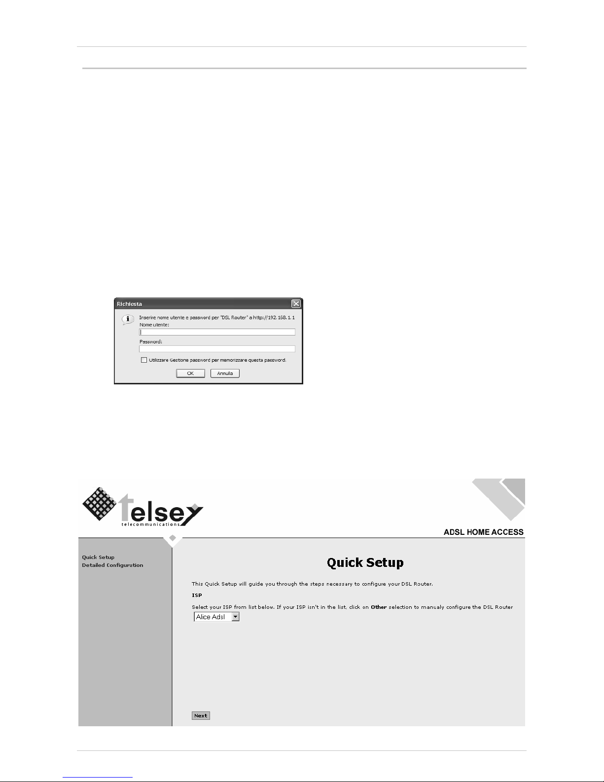
5) In a Web browser on the PC, connect to http://192.168.1.1/ to enter the Marty W-Gate's
configuration program. The browser should connect and you should see the Enter Network
Password screen. If the browser does not connect, the router may not have an image.
6) Type admin in the User Name and Password fields, and click OK. These values can be changed
later in the Web User Interface.
After login, the Quick Setup screen appears as shown in the following figure.

Marty W-Gate Installation Guide
19
It is possible to configure the Marty W-Gate by the Quick Setup (recommended option) or by the Detailed
Setup.
1
13
3.
.2
2.
.Q
Qu
ui
ic
ck
kS
Se
et
tu
up
p
After logon, the Quick Setup screen appears automatically. This configuration type allows to set the basis
parameters of the Marty W-Gate, in base of the parameters requested by your Internet Service Provider.
Before continue with the configuration, check the parameters request by your ISP, and then follow the
instruction in base of:
the ISP is included in the list that appears in the Quick Setup screen.
the ISP is not included in the list that appears in the Quick Setup screen.
T
TH
HE
EI
IS
SP
Pi
is
si
in
nc
cl
lu
ud
de
ed
di
in
nt
th
he
el
li
is
st
t
If the ISP is in the list proposed in the Quick Setup screen, select the ISP and click on Next button.
It compares the following screen. Fill in the PPP Username and PPP password of your ISP.
In the same screen there is also the possibility to enable the end of Internet connection after a specific time.
Select the Next button to proceed with Marty W-Gate Setup.
In this screen it is possible (but not necessary) to configure the IP address and Subnet Mask. It is also
possible to enable or disable the DHCP server.

Installation Guide Marty W-Gate
20
Press the Next button when these parameters have been configured, it appears the Wi-Fi configuration
screen where it is possible to enable the Wi-Fi.
If the Wi-Fi connection has not to be activated, select the Next button.
If the Wi-Fi connection has to be activated, select “Wireless enable”. The SSID and Password fields
appear on the screen to complete the Wireless network setup.
In default setting, the Wireless network name (SSID) is “telsey” but it is recommended to change it for
the safety of the Wireless network. Then fill in the Password (WPA-PSK) field in order to protect the
Wireless network.
It is possible to disable the Wireless network protection by selecting “Protection disabled” but this
operation it is not recommended.
When the Wi-Fi configuration is completed, select the Next button. It appears the WAN Configuration
summary. Check if the settings are compatible with the ISP requirements. Select Save and Reboot
button to confirm the configuration or select Back button to amend the configuration.
Table of contents


