Telular phonecell sx5e User manual

01/30/02 Part Number5602xxxx
P
HONECELL
®
SX5eGSM
F
IXED
W
IRELESS
T
ERMINAL
900 MH
Z
GSM
1800 MH
Z
GSM
1800 MH
Z
GSM
V
OICE
C
OMMUNICATION
C
OMPUTER
F
AX
/D
ATA
S
TANDARD
F
AX
(O
TIONAL
)
U
SER
’
S
M
ANUAL
Phonecell®SX5e GSM 2Technical Manual
Before installing your Phonecell®SX5e, carefully remove the contents from the shipping carton
and check for evidence of shipping damage. If damage is found, contact your Authorized
Telular Distributor or shipping agent immediately.
SAFE OPERATION INSTRUCTIONS
IMPORTANT! Before installing or operating this product, read the SAFETY AND GENERAL
INFORMATION section of this guide.
• Install the unit indoors.
• Install the unit on a hard, flat surface for proper ventilation.
• Do not expose the unit to rain or moisture.
•Do not place the unit on or close to sources of heat.
IMPORTANT NOTICES
TERMS AND CONDITIONS FOR USE OF PHONECELL®PRODUCTS ("Product")
These Terms and Conditions are a legal contract between you and Telular Corporation for the title to and use of the Product.
BY RETAINING AND USING THE PRODUCT AFTER RECEIPT OF IT, YOU AGREE TO THE TERMS AND CONDITIONS
INCLUDING WARRANTY DISCLAIMERS, LIMITATIONS OF LIABILITY AND INDEMNIFICATION PROVISIONS BELOW. IF
YOU DO NOT AGREE TO THE TERMS AND CONDITIONS, DO NOT USE THE PRODUCT AND IMMEDIATELY RETURN
THEUNUSED PRODUCTFOR ACOMPLETE REFUND.You agreeto acceptsole responsibilityfor anymisuse ofthe Product
by you; and, in addition, any negligent or illegal act or omission of your or your agents, contractors, servants, employees, or
other users of the Product so long as the Product was obtained from you, in the use and operation of the Product. Changes or
modifications not expressly approved by Telular Corporation will void your authority to operate the equipment per FCC part 15
paragraph 15.21.
INDEMNIFICATION OF TELULAR CORPORATION ("TELULAR")
YOU SHALL INDEMNIFY, DEFEND AND HOLD HARMLESS TELULAR FOR ANY OF THE COST, INCLUDING REASON -
ABLE ATTORNEYS' FEES, AND FROM CLAIMS ARISING OUT OF YOU, YOUR CLIENTS' OR OTHER THIRD PARTIES'
USE OR OPERATION OF THE PRODUCT: (i) FOR MISUSE OR IN A MANNER NOT CONTEMPLATED BY YOU AND
TELULAR OR INCONSISTENT WITH THE PROVISIONS OF THIS MANUAL; (ii) IN AN ILLEGAL MANNER OR AGAINST
PUBLIC POLICY; (iii) IN A MANNER SPECIFICALLY UNAUTHORIZED IN THIS MANUAL; (iv) IN A MANNER HARMFUL
OR DANGEROUS TO THIRD PARTIES; (v) FROM CLAIMS BY ANYONE RESPECTING PROBLEMS, ERRORS OR MIS-
TAKES OF THE PRODUCT; OR (vi) COMBINATION OF THE PRODUCT WITH MATERIAL, MODIFICATION OF THE
PRODUCT OR USE OF THE PRODUCT IN AN ENVIRONMENT NOT PROVIDED, OR PERMITTED, BY TELULAR IN
WRITING. THE PARTIES SHALL GIVE EACH OTHER PROMPT NOTICE OF ANY SUCH COST OR CLAIMS AND COOP-
ERATE, EACH WITH THE OTHER, TO EFFECTUATE THIS INDEMNIFICATION, DEFENSE AND HOLD HARMLESS.
PLEASE SEE THE IMPORTANT NOTICES SECTION OF THIS GUIDE FOR IMPOR-
TANT INFORMATION ON USE, WARRANTY AND INDEMNIFICATION
CONTENTS
Telular Corporation
Corporate Headquarters
647 North Lakeview Parkway
Vernon Hills, Illinois 60061, USA
Technical Support
Tel: 847-247-9400 · Fax: 847-247-0021
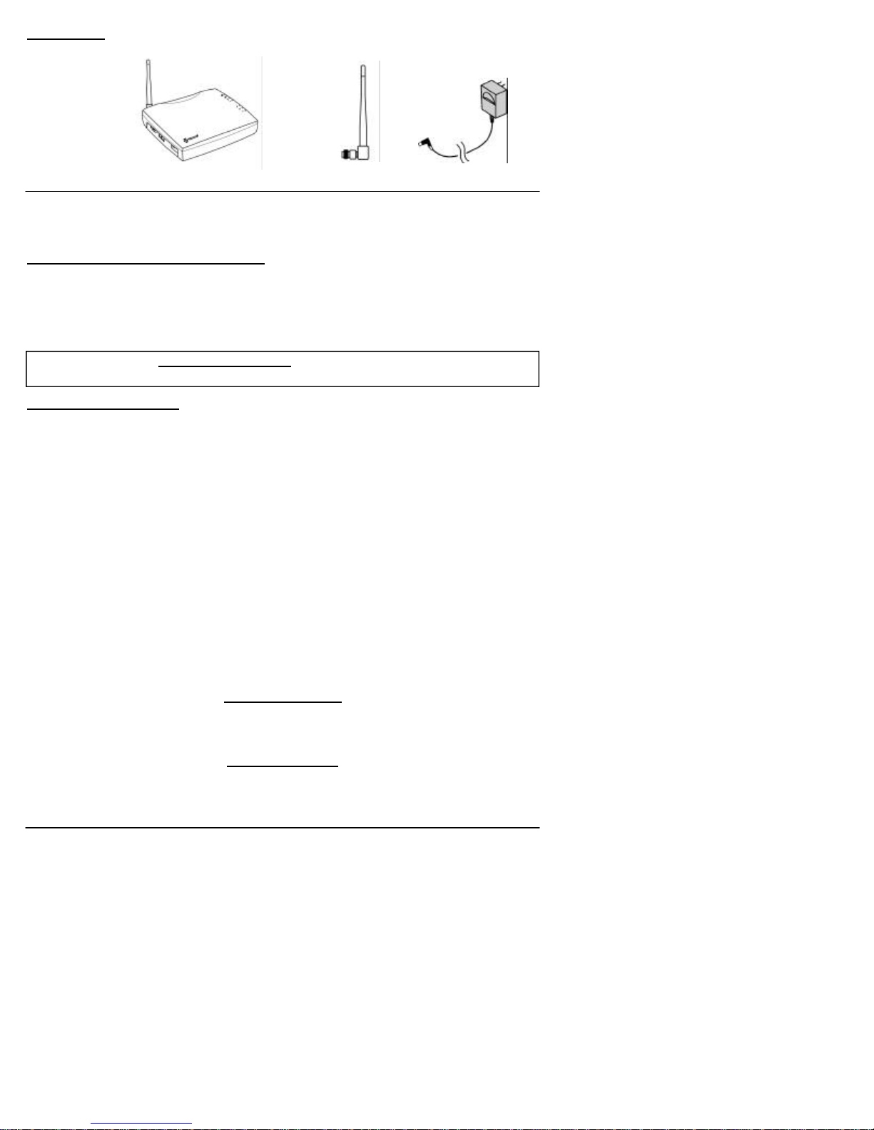
Power SupplyPhonecell®SX5e CDMA FWT Spike Antenna
Part Number 56023001 ©2002 Telular Corporation, All Rights Reserved

Phonecell®SX5e GSM 3Technical Manual
TABLE OF CONTENTS
Contents........................................................................................................................2
Safe Operation Instructions ........................................................................................2
Important Notices ........................................................................................................ 2
Installation.......................................................................................................................
Location and Setup ......................................................................................................
Optional Wall-Mount Instructions.................................................................................
Connect Your Phonecell®SX5 to AC Power...................................................................
Emergency Battery Backup .........................................................................................
Plug in Your Telephone................................................................................................
Phonecell®SX5 Operation .............................................................................................
How to Use the LED Status Indicators ........................................................................
How to Place a Call .....................................................................................................
How to Receive a Call .................................................................................................
How to End a Call........................................................................................................
The Hookflash Function...............................................................................................
Important Tones and Alerts ..........................................................................................
Supplementary Features (Network Dependent) ..........................................................
Call Waiting ..................................................................................................................
Three-Way Calling........................................................................................................
Call Forwarding............................................................................................................
Caller ID .......................................................................................................................
Voice Mail Service........................................................................................................
Digital Data Service ........................................................................................................
PC Data Connection ....................................................................................................
Sending Digital Fax......................................................................................................
Receiving Digital Fax ...................................................................................................
Data Communication (E-Mail)......................................................................................
Browsing the Internet...................................................................................................
Analog (Group 3) Fax Service (Optional)..........................................................................
Plug In A Fax Machine.................................................................................................
Sending A Fax..............................................................................................................
Receiving A Fax...........................................................................................................
Phonecell®SX5 Programming.......................................................................................
Programming Mode Overview .....................................................................................
How to Adjust Voice Volume........................................................................................
How to Change the Lock Code....................................................................................
How to Restrict Outgoing Calls....................................................................................
How to Set the Alarm...................................................................................................
How to Disable the Alarm ............................................................................................
How to Set Caller ID Mode..........................................................................................
How to Set 1 Minute Alert Beep...................................................................................
How to Set the Connecting Tone.................................................................................
How to Reset the Terminal...........................................................................................
Phonecell®SX5 Technician Programming ...................................................................
Phonecell®SX5 Troubleshooting..................................................................................
General Information and Safety....................................................................................
Warranty..........................................................................................................................
Appendix A: How to Setup PC Serial Ports for Phonecell®SX5
Computer Digital Fax/Data .........................................................................................

EXTERNAL CONNECTERS
LED STATUS INDICATORS
Phonecell®SX5e GSM 4Technical Manual
RSSI 3
RSSI 2
RSSI 1
Service Indicator
Hook Indicator
Message Indicator
Power/Battery
Antenna
(TNC)
SerialPort
(DB-9)
Fax or PSTN
(RJ-11) Phone
(RJ-11))
AC/Battery Switch
AC Power Input

Phonecell®SX5e GSM 5Technical Manual
INSTALLATION
Location and Setup
The Phonecell®SX5 comes with a standard spike antenna (TNC). For optimal signal strength,
choose a location that is above ground and as close to windows (or exterior walls) as possible -
See Figure 2. Cellular signal strength is displayed by the Received Signal Strength Indicator
(RSSI) LED on the unit - See the How to Use the LED Status Indicators section of this guide.
1) Connect the antenna to the side of the terminal - see Figure 1.
2) Finger-tighten the antenna; do not over-tighten.
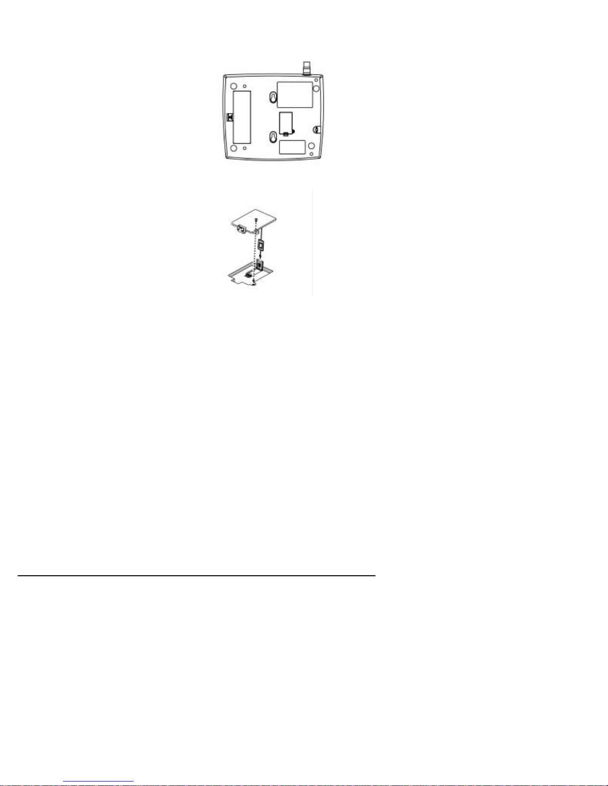
To Wall-Mount the SX5e
1) Mark two hole locations 98.5mm (3-7/8 inches) vertically apart and drill two holes into the
wall.
2) Install the screws (not supplied) into the wall, leaving a gap (approximately 3 mm (1/8 inch))
between screw head and wall.
3) Align the mounting holes with the screws and mount the Phonecell®SX5 onto the screws -
See Figures 3 and 4.
Figure 2 – For optimal call clarity, the antenna should
be pointed up and the SX5e located close to an exterior
wall or window.
Wall-Mount
Figure 1 –
SX5e antenna connection.
Spike
antenna
Figure 3 –SX5e mounting holes. Figure 4 – Mount the SX5e on screws.
TNCAntenna
Connector
Mounting Holes
Table Mount

Phonecell®SX5e GSM 6Technical Manual
To Connect Your Phonecell
®
SX5e to AC Power
1) Connect the barrel connector of the power supply to the AC power input receptacle of the
Phonecell®SX5 - See Figure 5.
2) Plug the power supply into the AC socket.
3) Press and hold the power button until the power LED is green - See Figure 5 and Figure 8.
4) Check the cellular signal strength and move the unit until you achieve the best signal possi-
ble - see the Received Signal Strength section of this guide.
Emergency Battery Backup
To Install the Battery
1) Open the battery cover on the bottom side
of the SX5e - See Figure 6.
2) Connect the battery cable to the battery
connector inside the battery compartment.
3) Insert the battery pack into the battery
compartment between the hold bars.
4) Close the battery cover.
To Attach a Telephone
1) Locate the modular line port on your
telephone and plug in one end of a
standard phone cord - See Figure 7.
2) Connect the other end of the phone cord
to the telephone port on the side of the
SX5e - See Figure 7.
NOTE: The SX5e does not support direct
computer modem (data) operation through the
phone port or fax port. See the Digital Data
Service section of this guide for computer
digital data operation.
Battery
Cover
Tabs
Figure 6 – SX5e battery installation.
Battery
Cover
Battery
Figure 7 - Connect SX5e to telephone.
PhoneCord
To
Phone
Port
Figure 5 –
SX5eAC power input.
AC Power
Power
Supply
Barrel Connector
AC Power Input

Phonecell®SX5e GSM 7Technical Manual
PHONECELL SX5E OPERATION
To Use the LED Status Indicators
1) Power-on the unit (see the Connect Your Phonecell ®to AC Power section of this manual).
2) The LEDindicators on the front of the SX5e will turn ON. The following tables describe the
modes and operation of the indicators.
Received Signal Strength Indicator LED’s
LED Activity Cellular Signal Strength
1Flashing Lowest
Continuous Poor
2Flashing Ok
Continuous Good
3Flashing Very Good
Continuous Best
Service Indicator LED
LED Color LED Activity Description
Green Continuous Full Service
Amber Continuous Limited Service
Red Continuous No Service
Flashing SIM Error
Hook Indicator LED
LED Color LED Activity Description
Green Flashing (with ringer) Incoming call
Continuous FWT is off hook
Fast Flashing Processing data call
Slow Flashing Call on hold
Message Indicator LED
LED Color LED Activity Description
Green Continuous New voicemail message
Slow Flashing New text message
Power/Battery
LED Color LED Activity Description
Green Continuous Power supply applied
Amber Continuous Battery power active
(battery switch on)
Red Continuous Battery low (battery switch
on)
Slow Flashing Batter low (power supply
applied
To Install the SIM
Card
The GSM module within the Phonecell®SX5 requires a Subscriber Identification Module (SIM)
for normal operation. The service provider supplies a SIM card, which carries the account infor-
mation needed to operate the Phonecell®SX5. The mini-SIM compartment is on the back of the
Phonecell®SX5 - see Figure 11.
1) Disconnect DC power.
2) Remove the SIM compartment cover by
removing the screw.
3) Open the SIM card holder.
4) Line up the mini-SIM card with the arrow on
the SIM card holder.
5) Gently insert the mini-SIM card in the slot of
the SIM card holder - See Figure 12.
6) Close the SIM card holder.
NOTE: If you insert the SIM card improperly, the
holder will not close. Do not force it shut. Make
sure the SIM card is aligned properly with the
directional arrow on the holder.
7) Reattach the SIM compartment cover with the
screw.
8) Reconnect DC power.
The mini-SIM may require entry of a Personal
Identification Number (PIN). The PIN is a four- to
eight-digit number provided with the SIM card. If
the service provider has set the SIM to require
PIN entry, the Phonecell®SX5 will request the
PIN each time it is powered ON or the SIM is
removed and replaced. The PIN can be stored
within the Phonecell®SX5 for automatic entry when required. To use the automatic PIN entry
feature, the PIN must be correctly programmed and automatic PIN entry must be enabled.
If PIN entry is requested while automatic PIN entry is disabled, the Phonecell®SX5 emits a SIM
Inactive tone. The SIM PIN can be manually entered at that time by dialing the PIN and press-
ing #. If entry is successful, the SIM Inactive tone will be replaced by service dial tone.
To Enable/Disable the Automatic PIN Entry Feature
1) Using a POTS (Plain Old Telephone Set) phone connected to the telephone port, lift up the
handset (take off-hook).
NOTE: You must have tone-dial (DTMF) capability to enable/disable the Automatic PIN Entry
Feature.
2) Enter the Programming mode:
Press: # * 0 * 1 2 3 4 5 6 7 8 #
The dial tone will cease upon entry of the first digit. If you enter the access code correctly, the
dial tone should change to a different, steady Programming tone and the bottom LED indicator
on the front of the Phonecell®SX5 will blink alternately RED and GREEN to indicate that you’re
in the programming mode.
3). Once in Programming mode:
Press: # * 65 * < auto_PIN> * <PIN> #
• To disable automatic PIN entry, set the "auto PIN" value to 0.
• To enable automatic PIN entry, set the "auto PIN" value to 1.
You must enter either 0 or 1, otherwise, the FWT will not update or store this value and the
existing stored parameter will remain. The factory default value is 0 (disabled). The factory
default PIN setting within the FWT’s non-volatile memory is "1234."
4) Correct entry will be confirmed by the return of the programming tone, which
signifies that the unit is ready to accept the next entry. Incorrect entry will result in a short,
three tone sequence of rising frequencies, followed by the return of the programming tone,
which again signifies that the unit is ready to accept the corrected entry.
Phonecell®SX5e GSM 8Technical Manual

5) Hang up the telephone handset (place on-hook).
For Example: To enable automatic PIN entry for PIN "1234," dial: # * 65 * 1 * 1234 #
Phonecell®SX5e GSM 9Technical Manual

To Change the PIN Value Entered by the Automatic PIN Entry Feature
Automatic PIN entry must be disabled when youl program the new PIN and Auto PINEntry.
1) Using a tone-dial (DTMF) POTS telephone connected to the Phone port, lift up the
handset(take off-hook).
2) Enter the Programming mode:
Press: # * 0 * 1 2 3 4 5 6 7 8 #
The dial tone will cease upon entry of the first digit. If you enter the access code correctly, the
dial tone should change to a different, steady “Programming” tone and the bottom LED indicator
on the front of the Phonecell®SX5 will blink alternately RED and GREEN to indicate that you’re
in the programming mode.
3) Press: # * 64 * < old_PIN> * <new PIN> * <new PIN> #
The new SIM PIN will be supplied by the service provider with a new SIM.
If the SIM card is changed, the PIN must be reprogrammed using the above command with the
correct new PIN for the new SIM.
NOTE: The factory default PIN setting within the FWT’s non-volatile memory is "1234."
4) Correct entry will be confirmed by the return of the programming tone, which signifies that
the unit is ready to accept the next entry. Incorrect entry will result in a short, three tone
sequence of rising frequencies, followed by the return of the programming tone, which again
signifies that the unit is ready to accept the corrected entry.
5) Hang up the telephone handset (place on-hook).
For Example: To set up a new SIM with PIN "5678," dial: # * 64 * 1 2 3 4 * 5 6 7 8 * 5 6 7 8
#
NOTE: This procedure will not change the PIN encoded on the SIM. It will only change the PIN
stored in the FWT for automatic entry of the PIN when requested by the GSM module.
If the SIM card in use has SIM PIN Entry enabled, it is strongly recommended that Automatic
PIN Entry be selected.
To Set a New PIN in the SIM
REMINDER: Automatic PIN entry must be disabled - before and while the SIM PIN is changed -
until programming of the new PIN and Auto PIN Entry (see previous page) is completed.
1) Using a tone-dial (DTMF) POTS telephone connected to the Phone port, lift up the handset
(take off-hook).
2) Press: * * 04 * < old_PIN> * <new_PIN> * <new_PIN> #
NOTE: You must know the old PIN to change it and the new PIN must be 4 to 8 digits (0 - 9) in
length.
3) Incorrect entry of the old PIN will be indicated by a short, three tone sequence of rising fre-
quencies. Hang up the telephone handset and start over at step 1 with the correct old PIN.
Incorrect length (less than 4 or more than 8 digits) of the new PIN or not entering the same
value in both new PIN entries will result in silence. Hang up the telephone handset and start
over at step1.
Correct entry will be confirmed by a short beep. Hang up the telephone handset.
For Example: To set up a new SIM with PIN "5678," where the old PIN is “1234,” dial: * * 04
* 1 2 3 4 * 5 6 7 8 * 5 6 7 8 #
NOTE: In case of PIN2, substitute the following step 2:
2) Press: * * 042 * <old_PIN2> * <new_PIN2> * <new_PIN2> #
NOTE: You must know the old PIN2 to change it and the new PIN2 must be 4 to 8 digits (0 - 9)
in length.
For Example: To set up a new SIM with PIN2 "5678," where the old PIN2 is “1234,” dial: * *
042 * 1 2 3 4 * 5 6 7 8 * 5 6 7 8 #
NOTE: This procedure will change the PIN encoded on the SIM. It will not change the PIN
stored in the FWT for automatic entry of the PIN when requested by the GSM module. (See pre-
vious page for instructions on how to enter the auto-entry PIN value).
Phonecell®SX5e GSM 10 Technical Manual

Phonecell®SX5e GSM 11 Technical Manual
To Unblock a SIM PIN
Use the following key sequence to unblock a SIM card:
1) Press: * * 05 * <PIN_unblocking key> * <new_PIN * <new PIN> #
2) Press: * * 052 * <PIN2_unblocking key> * <new_PIN2 * <new PIN2> #
NOTE: This procedure will change the PIN encoded on the SIM. It will not change the PIN
stored in the FWT for automatic entry of the PIN when requested by the GSM module. (See pre-
vious page for instructions on how to enter the auto-entry PIN value).
To Place a Call
1) Pick up your telephone handset (your phone is now “off-hook”).
2) Listen for dial tone (If service is not available, a No-Service tone is produced. Hang-up the
phone and try again. If the No-Service tone continues, contact your service provider to make
sure cellular service is activated.).
3) Dial the phone number.
To Receive a Call
When your telephone rings, pick up the handset and begin talking.
How to End a Call
Hang-up the phone (place the handset back onto the telephone cradle).
The Hookflash Function
When you initiate the Hookflash function, it automatically lets you:
Speed up the connection after you dial a phone number.
Answer an incoming call that occurs when you’re dialing a phone number.
Use special (supplementary) cellular services which may be available in your cellular service
area (see the Using Standard Supplementary Services section of this manual).
Tto Use the Hookflash Function
Depending upon your phone, there are two ways to initiate the Hookflash function:
Press the dedicated “HOOKFLASH” or “FLASH” key on your telephone.
Press the hang-up or switch-hook mechanism on your phone once quickly (approximately 1/2-
second).
Important Tones and Alerts
No-Service Tone – When cellular service is not available, the receiver emits a No-Service (fast-
beeping) tone instead of the normal (steady) dial tone.
ROH (Receiver Off-Hook) Tone – If the telephone equipment remains off-hook (off its cradle)
with no dialing activity for 45 seconds, the receiver emits an ROH tone for 60 seconds.
Incoming Call Alert – If you’re dialing a number and an incoming call occurs, the receiver will
emit an audible ring. To answer the incoming call:
Press the “HOOKFLASH” button once. This will connect the incoming call.
OR hang-up immediately. This will cause the phone to start ringing.
Supplementary Service Dial Tone – When supplementary services are enabled and active, the
receiver may emit a special dial tone to indicate that one or more services are active.
Roam Dial Tone – When cellular service is available, but the Phonecell®SX5 is in a Roam area,
the receiver may emit a different dial tone to indicate the roaming condition. However, unless
the FWT is re-programmed in the field, the factory default tone is set the same as normal serv-
ice dial tone.
Non-Registered Service Tone – When the SIM Card is inactive, missing from the Phonecell®
SX5, or installed but requires PINentry, the receiver emits a
non-registered service tone instead of the normal (steady) dial tone.

How to Use Call-Dependent Supplementary Services
Call-dependent supplementary services are those services handled within an active call. These
features are network-dependent. Check with your cellular provider to determine available fea-
tures.
Use the following commands to activate the call-dependent supplementary services:
NOTE: <send> is provided by the hookflash function (See the Hookflash Function section of
this manual).
To Release All Held Calls or Set User Determined User Busy For a Waiting Call:
Press: 0 <send>.
To Release All Active Calls and Accept the Held/Waiting Call:
Press: 1 <send>.
To Release a Specific Active Call x:
Press: 1 x <send> (x represents the call ID 1-7).
To Place All Active Calls on Hold and Accept the Held/Waiting Call:
Press: 2 <send>.
To Place All Active Calls on Hold Except Call x:
Press: 2 x <send> (x represents the call ID 1-7).
To Add a Held Call to the Conversation:
Press: 3 <send>.
To Place All Active Calls on Hold and Make the Call to the Specified Phone Number:
Press: PhoneNo <send>.
NOTE: When both a held and a waiting call exist in a conflicting situation, the above proce-
dures apply to the waiting call.
Call Waiting:
Permits a subscriber to be notified of an incoming call while the subscriber is engaged in an
active or held call. The subscriber can either accept, reject, or ignore the incoming call.
Activate: * 43 #
Deactivate: # 43 #
Interrogate: * # 43 #
Call Hold:
Allows a served subscriber, who is provisioned with this supplementary service, to interrupt
communication on an existing active call and then subsequently, if desired, re-establish commu-
nication. The traffic channel remains assigned to the subscriber after the communication is inter-
rupted to allow origination or possible termination of other calls.
To Adjust the Volume Level
If the volume level on your phone is too high or too low, you can adjust the levels using the key-
pad on your telephone. Note: your telephone must be in Tone-Dial (DTMF) mode to adjust the
levels.
To Increase Audio Level - Increase the audio level in steps by pressing:
# * 8 (also known as # * Up)
Continue to press # * 8 until the desired level is reached.
To Decrease Audio Level - Decrease the audio level in steps by pressing:
# * 3 (also known as # * Down)
Continue to press # * 3 until the desired level is reached.
NOTE: The default setting lets you adjust the audio up to three (3) steps from the default vol-
ume in either direction (Up or Down). The volume setting remains in effect for future calls until
changed manually, even if the telephone is on-hooked. If the Phonecell®SX5 power is cycled
(turned OFF/ON), the default mid-range volume setting will be restored.
Phonecell®SX5e GSM 12 Technical Manual

Variable Dial Time (Auto SEND Delay) Option
When you place a call, your Phonecell®SX5 automatically sends the phone
number over the cellular network after you dial the last digit – just like a landline phone.
However, to make sure you have enough time to dial the last digit, a 3-second Auto SEND
Delay is programmed into the unit at the factory. To change the Auto SEND Delay setting, see
the How To Set the Auto SEND Delay section of this manual.
Data After SEND (In-Call DTMF Signaling) Option
Depending upon your cellular provider, the Data After SEND option may need to be Enabled or
Disabled to use special cellular features such as call waiting, three-way conference calls, voice
mail, etc. Please consult your service provider for the required Data After Send/In-Call DTMF
Signaling configuration.
The factory default setting is 0 (In-Band Signaling only). To change the Data After SEND setting,
see the How To Set Data After SEND (In-Call DTMF Signaling) section of this manual.
Zero Dial Delay for Frequently Called Numbers
A new patented feature enables the Phonecell®SX5 to recognize your frequently called phone
numbers and send them immediately–without the 3-second Auto SEND Delay. The Phonecell®
SX5 stores a list of up to 50 numbers in its memory. This list contains any number that you’ve
called at least twice successfully.
NOTE: Cycling (turning OFF/ON) the power will erase the current list. A new list will be started
when power is re-applied. To enable or disable this feature, see the Enable/Disable Zero Dial
Delay for Frequently Called Numbers section of this manual.
Caller ID Format
The Phonecell®SX5 will support Caller ID device operation. The FWT factory default format is
designed to work for most Caller ID devices. If the Caller ID device does not respond, then
change the FWT Caller ID format using the programming command below. The Phonecell®SX5
can be programmed with an ordinary touch-tone telephone.
NOTE: The User Programming mode is not accessible during a call. Refer to
the Phonecell®SX5 Programming section of this manual to enter the Programming Mode.
To Enter Caller ID Format
The following key sequence is used to select the Caller ID format:
Press # * 84 * <CID format> #
The Caller ID Format factory default value will work for most Caller ID devices. If the Caller ID
device does not respond, program a value of 1 in the "CID Format" field. If the Caller ID device
still does not respond, then program a value of 2. If the value is not in the range 0 to 2, it is con-
sidered invalid and the FWT will not update or store this value; the currently stored value will
remain. The factory default value is 0.
When the FWT is programmed to Format 0, date and time information is not provided by the
FWT. When the FWT is programmed to Format 1 or Format 2, the FWT provides "January 1,
Midnight" as generic time and date information. The actual display of this generic date and time
("January 1, Midnight") will vary as it is determined by the Caller ID device.
For Caller ID Devices with Date and Time Display
When the Caller ID device is first powered, the date and time information will begin from
"January 1, Midnight." The user cannot change the date and time through the FWT.
When the Caller ID format is set to factory default 0, date and time will continue to advance.
Each incoming call will not affect the date and time.
When the Caller ID format is set to either 1 or 2, the date and time will be reset to "January 1,
Midnight" for each incoming call.
Phonecell®SX5e GSM 13 Technical Manual

Using Standard Supplementary Services
Your Phonecell®SX5 is compatible with a variety of special services, including:
Call Forwarding
Call Barring
Call Waiting
Three-Way Calling
Caller ID
Voice Mail
and more...
Depending upon your cellular provider, these services may be available on a
subscription basis. However, certain dialing sequences must be entered. Please consult your
service provider for the dialing instructions for your system.
Standard supplementary services are defined as those supplementary services handled while
not in a call. Depending on the supplementary service, several commands may be available.
The command list is defined below:
Registration - The programming by the user of information to enable subsequent operation of a
service. This action involves input of specific supplementary information. For example, when
call-forwarding registration is initiated by the user, a forwarding number must be supplied.
Erasure - The deletion of information stored against a particular service by a previous registra-
tion.
Activation - An action taken by the FWT user to enable a previously registered process to run.
Deactivation - An action taken by the FWT user to terminate the process started at activation.
Depending on the supplementary service, additional parameters may be required to successfully
complete an operation, such as phone number or password. Some supplementary services
have optional parameters, such as Teleservice and/or Delay settings. Delay is the amount of
time to wait before completing performance of a service that has a condition controlling its activi-
ty; for example, call forward on no answer waits an amount of time equal to the "delay" for the
phone to be answered before declaring no answer and forwarding the call.
Teleservice: 10 = All Teleservices, 11 = Speech, 12 = Data, 13 = Fax, 16 = SMS, 19 = All
Teleservices except SMS.
Delay: 5-30 seconds
PhoneNo: Up to 20 digits (0-9)
NOTE: <send> is provided by the hookflash function (See the Hookflash Function section of
this manual).
Call Forwarding Unconditional:
Allows a called subscriber to have the network send immediately all incoming calls, or just those
associated with a specific teleservice, addressed to the called subscriber's directory number to
another directory number.
Register:* * 21 * Ph No * Teleservice # <Send> or * 21 * Ph No * Teleservice #
<Send>
Erase:# # 21 * Teleservice # <Send>
Activate:* 21 * Teleservice # <Send>
Deactivate:# 21 * Teleservice # <Send>
Call Forwarding on Mobile Subscriber Busy:
Allows a called subscriber to have the network send immediately all incoming calls, or just those
associated with a specific basic service group, addressed to the called subscriber's directory
number and which meet "subscriber busy" to another directory number.
Register:* * 67 * Ph No * Teleservice # <Send> or * 67 * Ph No * Teleservice #
<Send>
Erase:# # 67 * Teleservice # <Send>
Activate:* 67 * Teleservice # <Send>
Deactivate:# 67 * Teleservice # <Send>
Phonecell®SX5e GSM 14 Technical Manual

Call Forwarding on No Reply:
Allows a called subscriber to have the network send all incoming calls, or just those associated
with a specific basic service group, addressed to the called subscriber's directory number and
which meet "no reply" for a specific amount of time to another directory number.
Register:* * 61 * Ph No * Teleservice * Delay # <Send>
Erase:# # 61 * Teleservice # <Send>
Activate:* 61 * Teleservice # <Send>
Deactivate:# 61 * Teleservice # <Send>
Call Forwarding on Mobile Subscriber Not Reachable:
Allows a called subscriber to have the network send all incoming calls, or just those associated
with a specific Teleservice group, addressed to the called mobile subscriber's directory number,
but which is determined to be "not reachable", to another directory number.
Register:* * 62 * Ph No * Teleservice # <Send>
Erase:# # 62 * Teleservice # <Send>
Activate:* 62 * Teleservice # <Send>
Deactivate:# 62 * Teleservice # <Send>
Call Forwarding All Call Forwarding:
Allows a called subscriber to have the network send-after the stated delay-all incoming calls, or
just those associated with a specific teleservice, addressed to the called subscriber's directory
number to another directory number.
Register:* * 002 * Ph No * Teleservice * Delay # <Send>
Erase:# # 002 * Teleservice # <Send>
Activate:* 002 * Teleservice # <Send>
Deactivate:# 002 * Teleservice # <Send>
Call Forwarding Conditional Call Forwarding:
Register: * * 004 * Ph No * Teleservice * Delay # <Send>
Erase: # # 004 * Teleservice # <Send>
Activate:* 004 * Teleservice # <Send>
Deactivate:# 004 * Teleservice # <Send>
Calling Line Identification Restriction:
If subscribed to in temporary mode, enable the calling party to countermand the subscribed-to
presentation of its line identity to the called party for a specific call (i.e., the next call) only. (If
subscribed to in permanent mode, the network will prevent presentation of the calling party’s line
identity to the calling party for every outgoing call.)
If subscribed to in temporary mode with default value “presentation restricted,” the user may
suppress CLIR, for the specific call only:
Register:* 31 # Call Phone Number <Send>
If subscribed to in temporary mode with default value “presentation not
restricted,” the user may invoke CLIR, for the specific call only:
Register: # 31 # Call Phone Number <Send>
Barring of All Outgoing Calls:
Allows a subscriber to have barring of certain categories of outgoing calls according to a barring
program which is selected from a set of one or more barring programs chosen at provision time
and is valid for all outgoing calls, or just those associated with a specific Teleservice.
Activate: *33 *Password *TeleService # <Send>
Deactivate: # 33 *Password *TeleService # <Send>
Phonecell®SX5e GSM 15 Technical Manual

Barring of Outgoing International Calls:
Outgoing call setup possibilities exist only to subscribers of the PLMN(s) and the fixed
network(s) of the country where the mobile subscriber is presently located.
Activate:* 331 * Password * TeleService # <Send>
Deactivate:# 331 * Password * TeleService # <Send>
Barring of Outgoing International Calls Except Those Directed to the Home PLMN
Country:
Outgoing call setup possibilities exist only to subscribers of the PLMN(s) and the fixed
network(s) of the country where the subscriber is presently located or to subscribers of the
home PLMN country of the served subscriber and to subscribers of the fixed network(s) in the
home PLMN country.
Activate:* 332 * Password * TeleService # <Send>
Deactivate:# 332 * Password * TeleService # <Send>
Barring of All Incoming Calls:
Allows a subscriber to have barring of certain categories of incoming calls according to a barring
program which is selected from a set of one or more barring programs chosen at provision time
and is valid for all incoming calls, or just those associated with a specific basic service group.
Activate:* 35 * Password * TeleService # <Send>
Deactivate:# 35 * Password * TeleService # <Send>
Barring of Incoming Calls when Roaming Outside the Home PLMN Country:
Calls which are terminated for the served subscriber is barred if the subscriber is roaming out-
side the home PLMN country.
Activate:* 351 * Password * TeleService # <Send>
Deactivate:# 351 * Password * TeleService # <Send>
All Call Barring:
On activation all calls is barred; on deactivation all call barring is disabled.
Activate:* 330 * Password * TeleService # <Send>
Deactivate:# 330 * Password * TeleService # <Send>
All Outgoing Call Barring:
On activation all outgoing calls is barred; on deactivation all outgoing call barring is disabled.
Activate:* 333 * Password * TeleService # <Send>
Deactivate:# 333 * Password * TeleService # <Send>
All Incoming Call Barring:
On activation all incoming calls is barred; on deactivation all incoming call barring is disabled.
Activate:* 353 * Password * TeleService # <Send>
Deactivate:# 353 * Password * TeleService # <Send>
Enter Caller ID Format Selection:
The following key sequence is used to enter the Caller ID format selection.
# * 84 * <CID format> #
The CIDformat value is set to 0 to select a CID Multiple Data Message Format (MDMF) with no
date of time information; set to 1 to select a CID MDMF with date and time information fixed at
midnight, January 1; set 2 to select a CID Single Data Message Format (SDMF) with the date
and time information at midnight, January 1. If the CID format is greater than 2, it is considered
invalid. The factory default is 0.
Unstructured Supplementary Services:
Allows a user and a PLMN operator-defined application to communicate in a way which is trans-
parent to the terminal and to intermediate network entities.
"any characters, from GSM 3.08 default alphabet" # <Send> or "1 or 2 characters, from
GSM 3.08 default alphabet" <Send>
Phonecell®SX5e GSM 16 Technical Manual

PHONECELLSX5 USER-PROGRAMMING COMMANDS
The Phonecell®SX5 can be programmed on location with an ordinary telephone, which is some-
times referred to as a POTS (Plain Old Telephone Set) phone. NOTE: the User Programming
mode is not accessible while you’re in a call.
In the following sections, an <entered value> comprises the digits 0 through 9. The digits '*' and
'#' are considered invalid when used inside an <entered value>, and will cause that
command/value to be rejected.
When you enter the programming mode, a timer is started. If there are no key entries within any
2-minute period, the FWT will revert to its normal mode. Going on-hook (hanging up the phone)
will exit the programming mode.
Correct entry of the commands below will be confirmed by the return of the programming tone,
which signifies that the unit is ready to accept the next entry. Incorrect entry will result in a short,
three tone sequence of rising frequencies, followed by the return of the programming tone,
which again signifies that the unit is ready to accept the corrected entry.
To Enter the User Programming Mode
Press: # * 0 * 1 2 3 4 5 6 7 8 #
The access code is 8 digits. If the access code is not 8 digits or does not match the access
code, the Programming mode cannot be entered. This code is pre-programmed during produc-
tion and cannot be changed in the field.
If you enter the access code correctly, the dial tone should change to a different, steady
“Programming” tone and the bottom LEDindicator on the front of the Phonecell®SX5 will blink
alternately RED and GREEN to indicate that you’re in the programming mode.
To Set Data After SEND (In-Call DTMF Signaling)
Press: # * 10 * <in-call DTMF signaling> #
The < > brackets represents the 1-digit in-call DTMF signaling option:
enter 0 for In-Band Signaling;
enter 1 for Out-of-Band Signaling;
enter 2 for both In-Band and Out-of-Band signaling;
enter 3 for neither.
The in-call DTMF signaling value is set to 0 for in-band signaling; 1 for out-of-band signaling, 2
for both in-band and out-of-band, and 3 for neither. If the in-call DTMF signaling value is greater
than 3, it is considered invalid. The factory default is 1 (In-band signaling).
To Set the Auto SEND Delay
Press: # * 11 * <delay> #
The < > brackets represent the Auto SEND Delay. You must enter a value between 2 and 20
seconds, otherwise the FWT will not update or store this value; the existing stored parameter
will remain. (For instance, to enter a 5-second delay, press: # * 11 * 5.) The factory default set-
ting is 3 seconds.
To Set the Pulse Dial Option
Press: # * 12 * <pulse-dial> #
The < > brackets represent the 1-digit Pulse Dial option:
enter: 0 to disable pulse dialing capability
enter: 1 to enable pulse dialing capability.
You must enter either 0 or 1, otherwise the FWT will not update or store this value; the existing
stored parameter will remain. The factory default setting is 1.
Phonecell®SX5e GSM 17 Technical Manual

To Enable/Disable Zero Dial Delay for Frequently Called Numbers
Press: # * 21 * <zero-delay dial> #
The < > brackets represent the 1-digit Zero Dial Delay option:
enter: 0 to disable Zero Dial Delay option
enter: 1 to enable Zero Dial Delay option
You must enter either 0 or 1, otherwise the FWT will not update or store this value; the existing
stored parameter will remain. The factory default setting is 1.
To Program the Output Level Option
Press: # * 69 * <output level> #
The output level value is set to 0 for low (-20dBm), 1 for normal (-14dBm) and 2 for high (-
8dBm). If the output level value is greater than 2, it will be considered invalid. The factory
default is 1.
Phonecell®SX5e GSM 18 Technical Manual

PHONECELL SX5E TECHNICIAN-PROGRAMMING COMMANDS
The following commands are to used by trained field technicians to set up the Phonecell®SX5
for operation in the network. Since these commands can directly affect the proper operation of
the unit, there is an additional level of security to prevent casual access.
To Enter Technician-Programming Mode
Press: # * 0 * 1 2 3 4 4 3 2 1 #
The access code is 8 digits. If the access code is not 8 digits or does not match the access
code, the Programming mode cannot be entered. This code is pre-programmed during produc-
tion and cannot be changed in the field.
If you enter the access code correctly, the dial tone should change to a
different, steady “Programming” tone and the bottom LED indicator on the front of the
Phonecell®SX5 will blink alternately RED and GREEN to indicate that you are in the
Programming mode.
To Enter Dial Tone After Remote On-Hook Option
Press: # * 8 * <dial tone option> #
The dial tone value is set to 0 for no tone after a remote on-hook; 1 to enable dial tone after
remote on hook. If the value is neither 0 nor 1, it is considered invalid. The factory default is 0.
To Enter Post Receiver Off-Hook Option
Press: # * 9 * <post ROH option> #
The post ROH value is set to 0 for continuous ROH tone; 1 to disable ROH tone and periodical-
ly check for an on-hook condition. If the post ROH value is neither 0 nor 1, it is considered
invalid. The factory default is 1.
To Enter Call-Answered Supervision Pulse Option
Press: # * 18 *
<cas_pls_enable> *
<cas_pls_freq> *
<cas_pls_duration> *
<cas_pls_level> #
Use the values specified below to program this option. Any values outside of those specified will
be invalid.
cas_pls_enable
0 = disable the pulse (default)
1 = enable the pulse.
cas_pls_frequency
0 = 12 kHz (default)
1 = 16 kHz
cas_pls_duration
values from 10 to 65535 (in 1 ms increments). Default is 100
cas_pls_level
0 = 0±3 dBm
1 = 3±3 dBm
2 = 6±3 dBm
3 = 9±3 dBm (default)
4 = 12±3 dBm
5 = 15±3 dBm
6 = 18±3 dBm
Phonecell®SX5e GSM 19 Technical Manual

To Enter Line-Reversal Outgoing Option
Press: # * 22 * <line_reversal_outgoing> #
The line-reversal outgoing value is set to 0 to disable line reversal, 1 to enable line reversal. If
the value is neither 0 nor 1, it is considered invalid. The factory default is 0.
To Enter Line-Reversal Incoming Option
Press: # * 23 * <line_reversal_incoming> #
The line-reversal outgoing value is set to 0 to disable line reversal, 1 to enable line reversal. If
the value is neither 0 nor 1, it is considered invalid. The factory default is 0.
To Enter On-Hook Call Alert Cadence Option
Press: # * 30 * <on-time> * <off-time> #
Both the on-time and off-time durations are programmed in 100 ms increments from 1 to 255
(0.1 - 25.5 seconds). If the value is not between 1 and 255, inclusive, it will be considered
invalid. The factory default is 20 and 40, respectively.
To Enter On-Hook Call Alert Frequency Option
Press: # * 32 * <frequency> #
The frequency value is set to 0 for 20 Hz, 1 for 25 Hz, and 2 for 50 Hz. If the frequency value is
greater than 2, it will be considered invalid. The factory default is 0.
To Enter Audio Input Impedance Option
Press: # * 68 * <audio Z> #
The audio Z value is set to 0 for 600 ohms, 1 for 900 ohms. If the value is neither 0 nor 1, it is
considered invalid. The factory default is 0.
To Enter Ring Back Request
Press: # * 13 * #
There is no ring back value to be set; the command activates when the phone is placed back
on-hook.
To Enter Restore Factory Defaults Request
Press: # * 15 * #
There is no restore defaults value to be entered; the command
activates immediately. If a value is entered, it is considered invalid and the Phonecell®SX5 will
not restore the factory defaults.
To Enter Periodic Self Test Option
Press: # * 76 * <self-test interval> #
The self-test interval is programmed in 1 minute increments from 1 to 65,535. A value of 0 dis-
ables periodic self test. If the value is not between 0 and 65,535, inclusive, it will be considered
invalid. The factory default is 180.
Phonecell®SX5e GSM 20 Technical Manual
Other manuals for phonecell sx5e
1
Table of contents
Popular Gateway manuals by other brands

CommScope
CommScope Touchstone TG6452 user guide

ZyXEL Communications
ZyXEL Communications P-660HW Series Compact guide

Foxconn
Foxconn IOTGW-TIX01 user manual

SMC Networks
SMC Networks DOCSIS 3.0 Commercial Cable Modem Gateway... Specifications

SICK
SICK WI180C-IOA00 quick start guide

LG
LG BECON HVAC BACnet PQNFB17C1 Installation & user manual


