tema AD630 User manual

AD630
VoIP SIP 25W PoE Horn Speaker
IP65 grade of protection
Audio Over IP Network Series
PRODUCT MANUAL
Version HW 1.0 - Version SW 1.08m
Revision
Date
Revision reason
Prepared
Checked/Approve
d
1 20/03/2017 Update MM, DP DP, FL
TEMA TELECOMUNICAZIONI
“IP COMMUNICATION AND SECURITY COMPANY”
WWW.TEMATLC.IT
Products for VoIP SIP LAN networking Communications, Paging Amplifiers Systems and
Audio Applications. Zone Announcements, Night Ringer, Multicast general call,
Background music, Standard SIP call or Emergency call, SD memory with pre-recorded
messages, Relays for LAN drives.

TEMA TELECOMUNICAZIONI
AD630VoIP SIP 25W / PoE Horn
MAS-AD630-REV01EN Page 2 of 46
We, TEMA TELECOMUNICAZIONI SRL Via C. Girardengo, 1/4 - 20161 MILANO
declare under our sole responsibility that the product:
Product name
Diffusore a Tromba VoIP SIP 25W PoE IP65
Trade name TEMA TELECOMUNICAZIONI Srl
Type or model AD630
and accessories --
to which this declaration relates is in conformity with the essential requirements and other
relevant requirements of the R&TTE Directive ( 1999/5/EC, 2006/95/EC, 2004/108/EC ).
The product is in conformity with the followings standards and/or other normative documents:
HEALT & SAFETY EN 60950-1:2006 +A11:2009 +A1:2010 +A12:2011
EMC EN 55022:2010, EN 55024:2010, EN 61000-3-2:2006
EN 61000-3-3 :2008
MILANO, 20 February 2017 TEMA TELECOMUNICAZIONI SRL
D. Pontillo
I.
IMPORTANT INFORMATIONS REGARDING THE RECOVERY AND RECYCLING OF THIS
ELECTRONIC DEVICE
DICHIARAZIONE DI CONFORMITÀ CE
DECLARATION OF CONFORMITY CE
The crossed
-
out wheeled bin symbol below indicates that this electronic equipment is
intended to be disposed in a separate collection and not in an unsorted municipal
waste, in order to provide for the treatment of WEEE (Waste Electrical and Electronic
Equipment) using best available recovery and recycling techniques. Specific treatment
for WEEE is indispensable in order to avoid the dispersion of pollutants and other
hazardous substances into the waste stream, while recycling leads to reduction of
disposal of waste and the negative impacts on environment and human health. That is,
priority is given to reuse of WEEE in its components, subassemblies and
consumables. As the final holder, the user has an important role in contributing to
reuse, recycling and other forms of recovery of WEEE and is responsible to return this
waste in the collection facilities set up by EC Member States and to fulfill other duties
in compliance with Directive 2002/96/EC and local laws.
UNI EN ISO 9001:2008
TEMA TELECOMUNICAZIONI is a certified company
TEMA TELECOMUNICAZIONI
AD630VoIP SIP 25W / PoE Horn
MAS-AD630-REV01EN Page 3 of 46
RECOMMENDATIONS
1. It is recommended to read this entire manual before proceeding to the installation of the device.
2. The installation and commissioning of the device can only be performed by specialized technicians.
3. The device is accurately manufactured and tested. In any case, the product is not recommended for use
where an error of operations can cause property damage and/or injury to persons.
4. It is expressly not recommended maintenance inside the device which must be carried out by Tema
Telecomunicazioni, the removal of the closures will invalidate the warranty and makes accessible internal
parts with risk of electric shock.
5. Tema Telecomunicazioni accepts no responsibility for damage to property and/or persons resulting from
incorrect use of the equipment or by procedures that do not comply with the instructions in this manual.
Tema Telecomunicazioni reserves the right to make modification to the technical and functional
specifications at any time and without any notice.
6. Products powered via PoE (Power over Ethernet) may only be connected with cables coming from the
internal network company (inside the building), are not allowed connections LAN cables coming from outside
the building.
7. Use for this device only and exclusively original spare parts and consumables supplied by Tema
Telecomunicazioni. The company is not responsible for damage caused by the use of materials not supplied
by the same.
8. Do not expose the unit to direct sunlight, protect from heat, dust, humidity and chemicals.
9. Tema Telecomunicazioni reserves the right to vary the product characteristics for improvement without prior
notice. Check the WWW.TEMATLC.IT website for any updates to the latest firmware, manuals, and
technical documentation.
10. This document is property of Tema Telecomunicazioni, It is forbidden any duplication and reproduction, even
partial, as well as storage onany mediumwithout written permission of Tema Telecomunicazioni.
This symbol in the descriptions indicates a general warning or a damage danger
to equipment or people.
This symbol in the descriptions indicates useful information or a suggestion for
the optimization of the device functionality.

TEMA TELECOMUNICAZIONI
AD630VoIP SIP 25W / PoE Horn
MAS-AD630-REV01EN Page 4 of 46
1. PRESENTATION ........................................................................................................................................ 5
2. FEATURES.................................................................................................................................................. 7
3. PACKING LIST ........................................................................................................................................... 7
4. TECHNICAL SPECIFICATIONS............................................................................................................... 8
5. OPERATION................................................................................................................................................ 9
5.1.
D
EVICE CONNECTION DIAGRAMS
..........................................................................................................................9
6. OPERATING MODES............................................................................................................................... 10
6.1.
C
ALLS TO DEVICES
...........................................................................................................................................10
6.2.
RELAY
FUNCTION
...........................................................................................................................................10
6.3.
C
ALLS GENERATED FOR ACQUISITION OF EXTERNAL CONTACTS FORSPECIAL SIGNALINGS
........................................10
6.4.
M
ULTICAST
A
UDIO
S
TREAMING
.........................................................................................................................11
7. COMMANDS AND CODES...................................................................................................................... 11
8. INSTALLATION OF THE DEVICE.......................................................................................................... 12
8.1.
M
OUNTING AND POSITIONING OF THE
AD630
HORN
.............................................................................................12
8.2.
O
PENING OF THE COVER AND ACCESS TO INTERNAL PARTS
-
PASSAGE OF CABLES
..................................................12
8.3.
C
ONNECTING THE INTERNAL MODULE OF
AD630.................................................................................................13
8.4.
C
ORRECT CONNECTION OF AN ADDITIONAL PASSIVE SPEAKER
..............................................................................15
8.5.
100V
AUDIO LINE FOR ADDITIONAL SPEAKERS AWAY FROM
AD630
IP
H
ORN
..........................................................16
9. PROGRAMMING ...................................................................................................................................... 17
9.1.
P
REPARATION FOR THE SYSTEM PARAMETERS PROGRAMMING
..............................................................................17
9.2.
A
CCESS TO PROGRAMMING
...............................................................................................................................19
9.3.
N
ETWORK PARAMETERS
...................................................................................................................................20
9.4.
SIP
P
ARAMETERS
...........................................................................................................................................21
9.5.
G
ENERAL PARAMETERS
....................................................................................................................................22
9.6.
S
ET OF THE OPERATING MODE
..........................................................................................................................23
9.7.
R
ELAY AND ALARM INPUT SETTINGS
...................................................................................................................24
9.8.
C
AMERA
.........................................................................................................................................................25
9.9.
C
ALL BUTTONS
................................................................................................................................................26
9.10.
M
ESSAGES MANAGEMENT
...........................................................................................................................27
9.11.
C
ALLS
R
EPORT
..........................................................................................................................................29
10. MAINTENANCE........................................................................................................................................ 30
10.1.
S
YSTEM
....................................................................................................................................................30
10.2.
L
OGIN CREDENTIALS
...................................................................................................................................31
10.3.
D
IAGNOSTIC LOGS
......................................................................................................................................31
11. PRESENTATION AND USE OF THE "AA Video Console" SOFTWARE........................................ 32
11.1.
P
RESENTATION
..........................................................................................................................................32
11.2.
S
OFTWARE CONFIGURATION FOR
SIP
S
ERVER MODE
.....................................................................................33
11.3.
S
OFTWARE CONFIGURATION FOR
P
EER
-T
O
-P
EER MODE
.................................................................................34
12. Introduction to AA-Video Console APP version for operating systems iOS...............................35
12.1.
D
OWNLOADING AND INSTALLING THE APP
......................................................................................................35
12.2.
U
SING THE APPLICATION
.............................................................................................................................37
13. Introduction to AA-Video Console APP version for ANDROID systems...................................... 37
13.1.
D
OWNLOADING AND INSTALLING THE APP
......................................................................................................37
13.2.
U
SING THE APPLICATION
.............................................................................................................................39
14. APPENDIXES............................................................................................................................................ 41
14.1.
A
PPENDIX
1:
O
THER EXAMPLES OF
M
ULTICAST
A
UDIO
S
TREAMING APPLICATIONS
.............................................41
14.2.
A
PPENDIX
2:
U
SE OF THE
VLC
M
EDIA
P
LAYERSOFTWARE AS A
M
ULTICAST
E
NCODER FOR AUDIO FILES
..............43
14.3.
A
PPENDIX
3:
U
SE OF THE
AUDACITY
SOFTWARE FOR AUDIO FILES RECORDING
...............................................44
14.4.
A
PPENDIX
4:
C
ABLING OF A
UTP
RJ45
NETWORK CABLE ACCORDING TOTHE STANDARD
EIA568B.....................45
INDE
X
PAGE
TEMA TELECOMUNICAZIONI
AD630VoIP SIP 25W / PoE Horn
MAS-AD630-REV01EN Page 5 of 46
1. PRESENTATION
AD630 allows to realize Paging Amplification Audio Sound Systems in a standard LAN network completely
integrating with IP-PBX SIP in order to be able to play announcements from any telephone in the internal network
and any technologies: analog, SIP, Smartphones and Softphones.
Access can be authorized by Password with code to be typed before starting the announcement. Two internal
relays can be programmed to be automatically activated when it is called or to be controlled from the phone via
LAN that originated the call to the AD630 horn, eg. to report the event to any auxiliary devices connected
downstream.
The system programming is done remotely via LAN thanks to the integrated Web server. AD630 incorporates an
efficient 40W (2x20W) Class-D amplifier.
2nd SIP Account – Night Ringer. AD630 can be registered on the PBX with a second telephone number, different
from the one used for ads and inserted in the night ring group. To the arrival of an incoming call, the system plays a
sound (user selectable) to all the network speakers. The volume can be adjusted independently of the others
managed audio channels.
Inputs from external contact with a variety of functions, for example: provide to make a SIP call to a
preprogrammed number and inform the operator of the event with an appropriate voice message. The signaling
can be repeated a number of programmable times, the operator can interrupt the sequence with a keyboard code.
Other examples of use will follow in this manual.
Multicast Audio Streaming for music and announcements diffusion. AD630 handles up to 5 multicast channels in
LAN with priority levels to allow the background music broadcasting on loudspeakers network. The generation of
musical programs in streaming audio can be managed froma PC of the LAN/WAN network with special software or
special TEMA Encoder.
Service "SIP Security Info Call" - Emergency SIP Call. By connecting a button or an external contact, AD630 can
call a phone number programmed to alert the event with a specific warning message. It is a security service for
emergencies or simple request for help and information, and allows a one-way phone call.
Total remote management via LAN, integrated Web Server. Programming, configuration, loading and listening to
audio files, firmware release update, audio volume adjustment, backup and restore the configuration, device
reboot.
Possibility to connect one or more external passive loudspeakers on the 2nd amplifier to expand audio coverage
of the served area. High power output of 20W when powered with an external power supply, automatic lowering of
the power with 10W limitation when powered only from LAN cable via PoE.
Tested with most popular P X brands:
SIEMENS - AVAYA - ALCATEL – PANASONIC – SAMSUNG - NEC -
LG
WILDIX - AASTRA - ASCOM - VT NITSUKO - SELTA – PHILIPS
TEMA TELECOMUNICAZIONI
AD630VoIP SIP 25W / PoE Horn
MAS-AD630-REV01EN Page 6 of 46
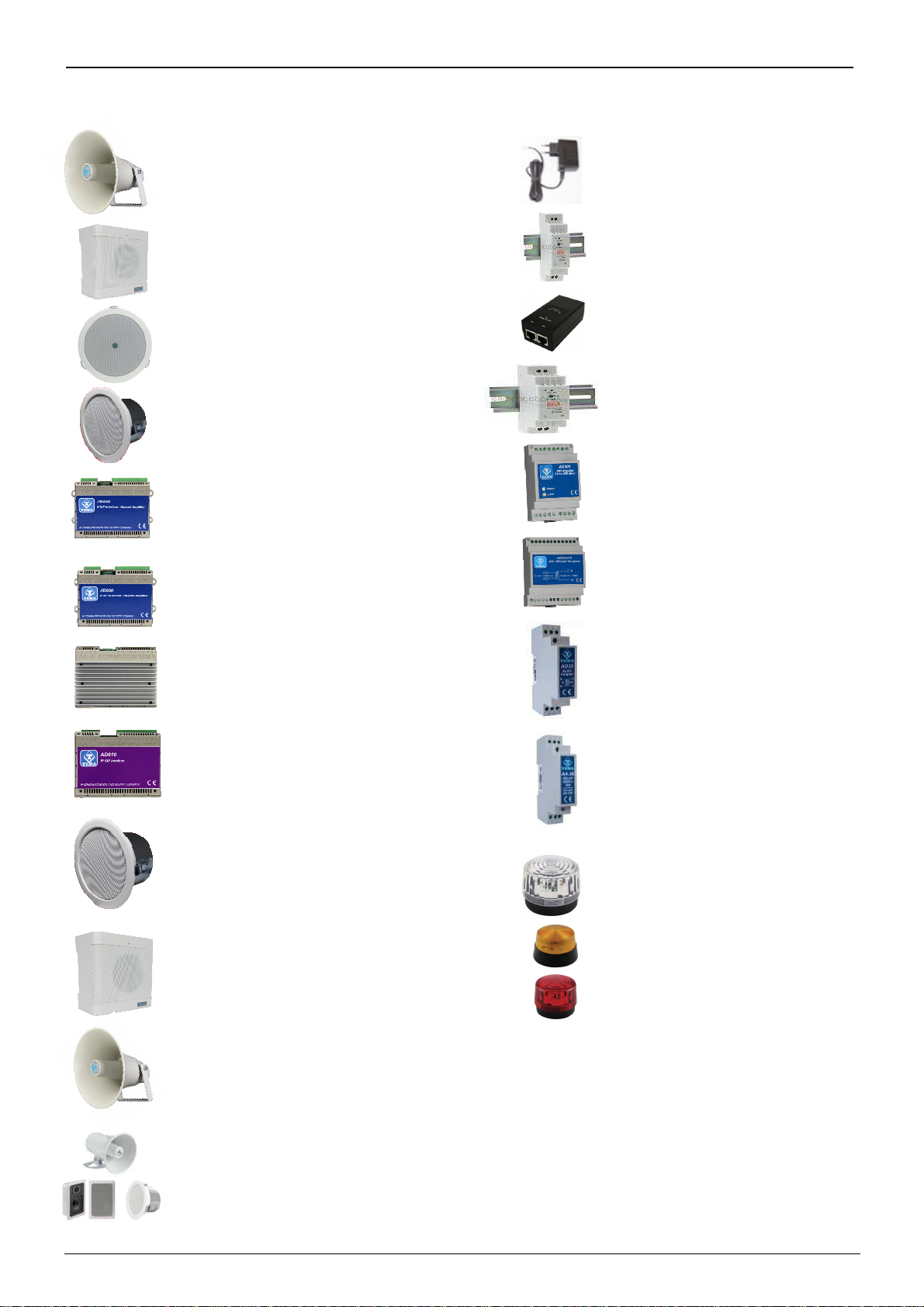
VoIP SIP Amplifiers-Speakers Products and Accessories of the AD600
“SipComStage”
series
AD610
2X2W PoE IP-
SIP Amplifier Module,
External Amplifier Adapter with Sound Isolation
Transformer. Directly pilot external power
amplifiers or 8 Ohm external passive speakers.
AD611
IP-
SIP PoE 10W Amplifier Module
(2X5W). Directly pilot 8 Ohm external passive
speakers.
AD633
IP-SIP speaker 12W PoE
open-to-ceiling version.
AD635
IP-
SIP PoE 12W speaker for wall
mounting with the possibility of integrating a PoE
injector adapter.
AD333/12XTP
Passive 8 Ohm 12W
speaker with anti-
flame cover (AD333/12TP
without cover), internal transformer for 100V
audio line. Ideal for connecting to AD610-611-
612
or as 2nd speaker to the AD63x series IP-
SIP
speakers.
AD335/06TP
Passive 8 Ohm 6W speaker
with 100V audio line transformer. Ideal for
connecting to AD610-611-
612 or as 2nd speaker
to the AD63x series IP-SIP speakers.
AD330/25T
Passive horn speaker 25W 8
ohm with transformer for 100V audio line. Ideal
for connecting to the AD610-611-
612 modules or
as 2nd speaker for AD63x IP-
SIP speakers
series.
AD330/
Are available Speakers of
different pow
er, Horns and Loudspeakers for
flush and ceiling mount.
AA
-
39DL
Plug Power Supply 220Vac/12Vdc-1,0A.
AA
-
39D1A
DIN Power Supply 220Vac/15Vdc-1,0A.
A
A
-
39P4
PoE injector 230Vac/48Vdc 0,5A.
AA
-
39E3 /
-
E6V
DIN Power Supplies 220Vac/24Vdc-1,5A
220Vac/24Vdc-2,5A.
AA
-
36
Protected Power Relay
Actuator 250Vac/16A/4KVA, command in
AC/DC 12V/24V, 1 contact, Led, contacts
protected by electric arcs.
Ideal for
driving loads up to 4.000W.
AD612
IP-
SIP PoE 40W (2x20W) Amplifier
Module when powered with an external power
supply.
Directly pilot 8 Ohm external passive
speakers.
AA
-
697
Flash lights with Xeon
lamp or high brightness LEDs. Ideal to be
controlled by the relay of the IP-
SIP
speakers of the AD630 series or by the
IP-
SIP amplifier AD610, AD611, AD612
modules, with a call in progress add a
light signal to the acoustic signal.
AD320/30
PA 100V audio line
transformer 30W, constant voltage, high
efficiency toroidal type with low magnetic
flux leakage.
AD32
Isolation transformer, balanced,
mixer, attenuator, audio signa
l filter, low
impedance output. Ideal for decoupling
devices of audio sources to other
amplifiers to eliminate noises.
AD615/S
Audio Encoder Module from
analog to digital on LAN Network in
Multicast/Broadcast Channels.
AD301R
30W analog amplifier,
2 channels, Volume-High-Low +/-
12dB
controls
AD630
IP-
SIP PoE 25W Horn Speaker
with 40W internal amplifier (2x20W) IP65
protection.
AD633C
SIP IP-
12W PoE Speaker ceiling
version with IP54 flameproof cover.

TEMA TELECOMUNICAZIONI
AD630VoIP SIP 25W / PoE Horn
MAS-AD630-REV01EN Page 7 of 46
2. FEATURES
•
IP 25W PoE horn for indoor/outdoor installation, IP65 degree of protection
•
Audio output power 40W (2x20W) with external power supply, 10W (2x5W) with PoE power
•
Possibility to register a second SIP account for the "Night Ringer" feature
•
5 RX Multicast Channels for Music/Ads/Messages diffusion with 5 priority levels
•
2 remote controlled relays via LAN
•
1 multifunction input from external dry contact
•
Possibility of playing a pre-recorded announcement, associated with the available input, or up to 6
announcements by making a call and sending the respective code via telephone
•
Notification service with dedicated messages following external event
•
2 buttons inputs for direct call to SIP numbers differentiated by communication/alert
•
“SIP Security Info Call” warning/emergency telephone call, sending of pre-recorded messages on
loudspeakers and on the called
•
"Push to Talk" function to control the direction of communication froman external button (Not included)
•
Independent adjustment of audio volumes: communications, multicast, night ringtone, alert tones
•
SD memory card with audio files from 16sec. customizable by the user (opt. up to 960min. - 16h audio)
•
Great versatility with ease of use and programming
•
VoIP connection with standard SIP Proxy Server protocol
•
Compatibility with all IP-PBX of the most prestigious brands
•
P2P (Peer to Peer) for operation also without IP-PBX
•
Power supply via PoE (Power over Ethernet) with a single UTP cable or external power supply, also at the
same time
•
Free APP developed for smartphones/tablets with iOS and Android operating systems
•
AA-Videoconsole software forWindows XP/7/10 PC for management of TEMA IP terminals included
•
Programming via dedicatedWeb Interface with password protection
•
Possibility of software / firmware update via LAN
•
Integration with the local LAN, 100BaseT Ethernet LAN port with RJ45 connector
•
Dimensions 240 x 240 x 290 mm
•
Wall mounting, ceiling mounting, indoor/outdoor sheds, on surveillance zones, etc..
3. PACKING LIST
The systems are supplied with the parts included in the following list:
•
An IP horn speaker device cod.AD630
•
A 3mt LAN cable connected internally to the horn for pre-installation test functions
•
A printed system documentation, installation, programming, use manual
•
A CD-ROM with complete documentation
TEMA TELECOMUNICAZIONI
AD630VoIP SIP 25W / PoE Horn
MAS-AD630-REV01EN Page 8 of 46
4. TECHNICAL SPECIFICATIONS
LAN
TCP/IP Network 10/100BaseTx
Protocols
SIP 2.0, RFC 3261
RTP Multicast audio Streaming
G.711 a
-
Law, µ
-
Law
Connection
SIP Server (IP
-
PBX) o
r
P2P (Peer To Peer)
Power Supply
PoE, PoE Injector and/or
external
Ac/Dc
power supply
PoE
802.3af class
0 12,95W
External Power Supply
(Op
t
.)
230Va
c / 12
-
15
Vdc
-
1A, 24Vdc
-
2A
Tec
hnology
IMX25 400MHz
Microprocessor
Memory
256MB Ram, Micro
-
SD Flash 2GB
Programming
practicalWeb interface and password
APP
for Smartphones
iOS, Android
Messagges/S
o
unds
prerecorded in the inte
rnal SD memory card
Audio File Format
Windows .wav
–
8K
–
16 bit
Duration
16sec each
. Standard (Option up to 960 min.
16H audio)
Bandwidth
300Hz
–
7KHz
Power
Class
-
D 10W amplifier (PoE), 20W (
E
xt. Power Supply)
S
ound pressure
117dB A (SPL)
D
ispersion
angle
100° @ 2KHz
Audio communication
Unidirectional / Bidirectional / Push to Talk
Internal Microphone
Omni
-
directional electret 30Hz
-
18KHz
A
dditional speaker output
1 output for external speaker, passive
,
impedance 8 Ohm
A
utomatic
c
heck mode
Through
self audio feedback
Inputs from buttons
or external contacts
2
for
buttons + 1 for warning
/alarm
Integrated relays
2
R
elay contacts
c
apacity
max 30Vdc
–
1,5A
Signalings
Active call Led, call tone, Ding
-
dong ads
Installation
Ceiling
mount, wall mount
Housing Material
Alumin
i
um and ABS
Grade of protection
IP65,
weather resistant
(AD630)
Storage temperature
From
-
20°
to
+65°C
Operating temperature
From
-
20° to
+55°C
Relative humidity
Up to
100%
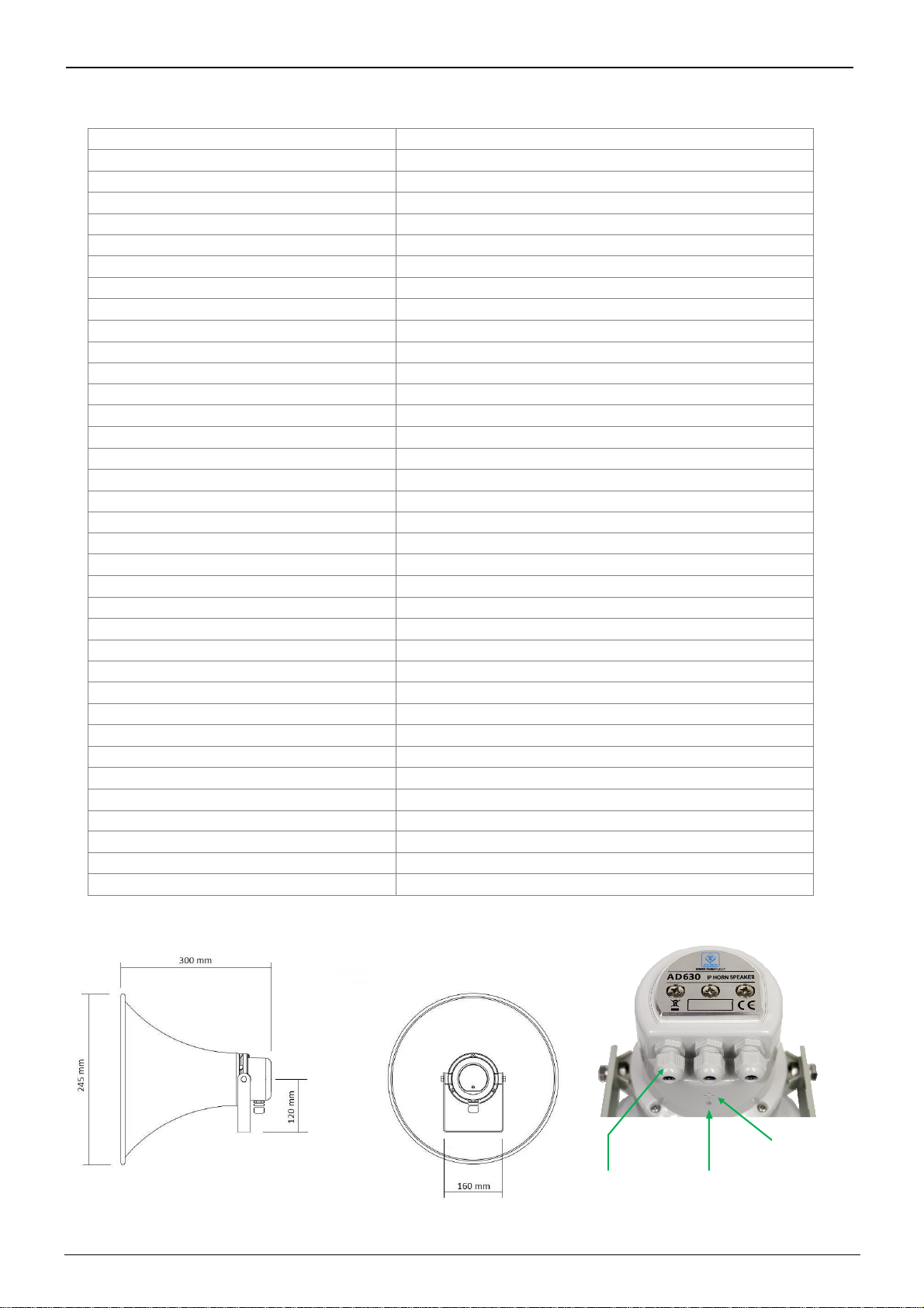
Dimensions
245 x 245 x 300
mm
Wei
ght
2,1 Kg
W
arrant
y
2
years, possibility of extension (
O
ption)
Compatibility
CE, ROHS
Cable gland for
external
connections
Ca
ll in
progress
Led
Microphone
TEMA TELECOMUNICAZIONI
AD630VoIP SIP 25W / PoE Horn
MAS-AD630-REV01EN Page 9 of 46
5. OPERATION
In stand-by and correctly configured, the system waits for incoming calls.
The device allows also the “streaming” Multicast sound diffusion. In this case the RTP audio diffused in LAN will be
played amplified by the AD630 horn. Differing from the announce mode on direct call, with multicast mode, more
devices can diffuse the same message at the same time, useful for general pre-recorded ads or for music sound
diffusion.
The operator who want to make an announcement on the device will make a call, from any extension of the PBX, to
the number to which the device is registered or to its IP address in the case of Peer-to-Peer connection.
It is always monitored the change status of an alarm input to which it is possible to associate a number to call and a
message to be played to the called party answer. It is possible to make common adjustment of the level output of
the speakers to better suit the acoustic characteristics of the served area.
The system can activate a relay contact for signaling to external devices.
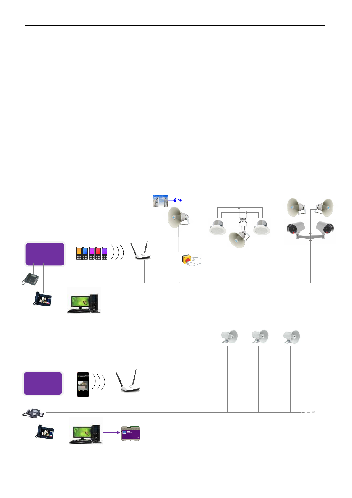
5.1. Device connection diagrams
Analog
audio
IP PBX
Access Point
IP SIP
Phone
Network PC used as a
multicast control
station with VLC
Smartphone
with
EMA APP
Zone 1
Zone 2
Zone 3
TEMA
AD615/S
Mini Encoder
Multicast Audio Streaming for sound diffusion
Each AD630 is accessible from IP-PBX registered SIP phones and smartphones that can launch an
advertisement. With the help of an encoder EMA AD615 it is possible to stream music on
multicast channels managed by AD630, the music is taken in analogue audio from the PC (or any
audio player) and sent to the Encoder that will redistribute on the LAN. he announcement from a
SIP call to a specific AD630 device will stop the music that will be automatically restored at the end.
AD630
Access Point
IP PBX
ZONE 3
AD630IP Horn plus
an additional 8 Ohm
passive horn to support
cameras
ZONE 2
IP Horn with other
passive speakers on a 100V
line created by adding a
transformer AD320 / 30
ZONE 1
AD630 IP Horn
with relay remote
control and call button
“Push o alk”
call button
Application with IP
-
PBX or Peer to Peer
Each IP Horn can be reached from SIP phones, Smart-phone
and other registered terminals in the IP-PBX that can launch
ads. he integrated relay can be operated from the SIP phone
that originated the call. With a Network PC with installed the
free software EMA "Videoconsole" it is possible to make
calls to IP speakers. If the free sofware "VLC" is also installed,
it will possible to send on Streaming Audio speakers multicast
channels, interrupted by ads as background music. In each
AD600 series speaker, it is possible to independently adjust
the audio volume reproduced via LAN thanks to the
integrated web server.
IP SIP
Phone
Network PC
Smartphone
with
EMA APP

TEMA TELECOMUNICAZIONI
AD630VoIP SIP 25W / PoE Horn
MAS-AD630-REV01EN Page 10 of 46
6. OPERATING MODES
6.1. Calls to devices
Call from the PBX phones to the AD630 systemallows to make announcements to the network speaker. However,
it is a normal telephone call, typically unidirectional although AD630 makes possible to hear the sound present in its
vicinity, being equipped with an internal microphone. Calling the extension number connected to the systems, they
will answer after a set time. It is also possible to have an appropriate code to protect the function fromunauthorized
access. Hang up to end the announcement. Any background music will be automatically restored.
6.2. RELAY function
The relays are typically used to signal to any auxiliary external devices that the announce is played, automatic
activation call per call. If not used for the function described above it is available and can be controlled with an
appropriate code fromthe caller's telephone.
6.3. Calls generated for acquisition of external contacts for special signalings
Are the calls that the system generates on his line to alert after triggering the alarm by the equipment input contact
connected (aux devices or a button available to users in the proximity of the device). At the answer it is played to
the called a pre-recorded message. It is possible to assign a phone number or an IP address that will be called
when the input is activated. It is possible to determine the activation status of the same. It is the closure of the
external contact that triggers the sequence of signaling but it is also possible to reverse this logic, in this way the
signaling can take place after the opening of the contact (normally closed) connected to the input.
AD630 continuously monitors the status of the contact in the event of the condition of the activation stored on non-
volatile memory card. As soon as possible it will begin to call the person who will manage the situation found at the
telephone number programmed reproducing the message associated with the event. It is also possible to choose to
play on a local speaker and on any connected audio output a pre-recorded message, which will be played prior to
the call to alert the present persons in the area served by the system detected event. It is possible to define an
acquisition/silencing code of alarm signaling that the called must type to inform the device of the alarm
acknowledgment. If the called number is busy or does not reply, or in any other case where AD630 does not
receive the capture/acknowledgment code, at the end of each call attempt return in standby and prepares itself for
a new alarm notification
When the systems receive the correct acquisition/acknowledgment code related to the alarm in progress, the alter
signaling will stop and will not be carried out further alarm notification calls. In order to be ready again, it is
necessary that the condition which had triggered the previous notification returns in standby. Only at the
occurrence of a new activation of the contact condition the calls cycle with the alert notification will start again. In
practice: if a connected contact is closed and it is detected its activation, AD630 starts to make warning calls.
In the event that the person called by the system answers and successfully enter the acknowledge code, the alert
calls will be terminated. If the contact that had triggered the alert, however, remained closed (this obviously
depends by the external device that controls the contact) will NOT be triggered another warning cycle! To have new
alerts for this contact, it is necessary that come back in standby before (reopening) and then to its new next
possible closure will be detected from AD630 system with new telephone alerts.
TEMA TELECOMUNICAZIONI
AD630VoIP SIP 25W / PoE Horn
MAS-AD630-REV01EN Page 11 of 46
6.4. Multicast Audio Streaming
In a LAN network, the Multicast term indicates the possibility to distribute an information like data, audio or video, to
a group of IP terminals of the Ethernet network. For Multicast are used class D IP addresses and they range from
224.x.x.x to 239.x.x.x. In our case the AD630 system is able to receive audio in Multicast into the specific IP
channel and play it amplified. The audio can be generated from a PC software application (for example VLC) or by
a IP SIP phone. The received audio stream is played without the intervention of any operator, this function is useful
for playing back voice messages and information or emergency announcements (also called "Paging" mode).
Obviously the Multicast audio streaming is unidirectional, the audio stream is sent from source to destination, but
not vice-versa. The audio stream can be sent simultaneously to multiple terminals (same IP Multicast), or only to
distinct terminals (each provided with its own IP address). It is possible to program up to 5 receiving addresses of
multicast streaming, each with its own priority, so that the same terminal if it is already playing audio (music for
example) may be interrupted by a higher priority stream (for example, an advertisement). Audio must be in G.711
format (aLaw or µLaw).
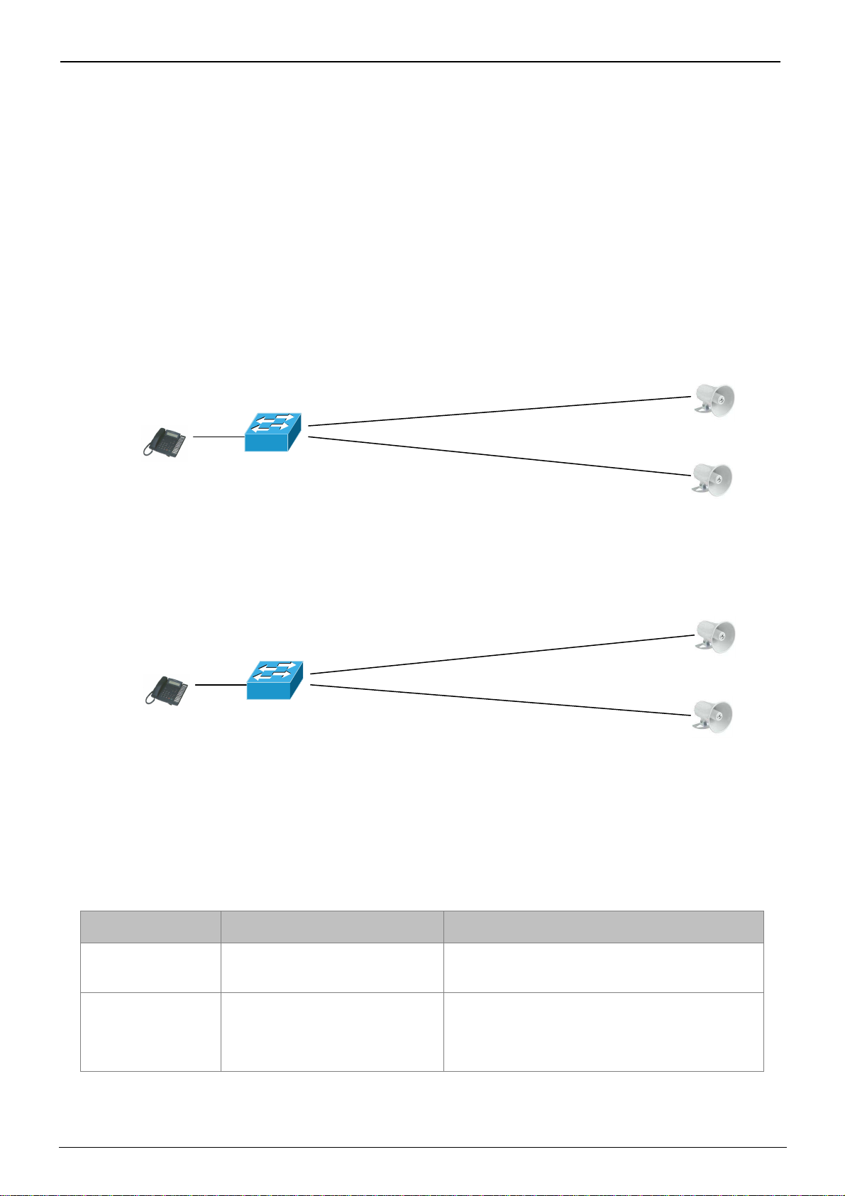
Example 1
In a plant, there are two systems, connected to the same network switch. From a suitable phone, it is possible to
make a voice announcement via multicast address 239.255.12.42:
Both systems will play the announcement audio message. Many more devices than those given in the example can
be connected, since there are no limits.
Example 2
In the plant there are two systems with different Multicast addresses.
The phone, selecting to send the multicast voice to one or other address of the terminal, will decide which device
must play the streaming message.
7. COMMANDS AND CODES
During the announcement will be possible to send the commands described here (which will be these by default):
DTMF Command
Function Description
#1 - #2 Activate the relay contact
1 or 2
Used to manually activate the relays if not
programmed to be automatically activated per
announcement.
#5 Extension of announcement
time
AD630 alert the operator with some tones 30 seconds
before the expiration of the time for the
announcement. Having to extend the announcement
over the set time it is possible to recharge original time
to continue the conversation (with this code).
Phone Extension
designed for
Multic
ast
LAN Switch
AD630
n. 1 Multicast
address
239.255.12.42
AD630 n. 2
Multicast
address
239.255.12.42
Phone Extension
designed for
Multicast
LAN Switch
AD630
n. 1 Multicast
address
239.255.12.42
AD630 n. 2 Multicast address
239.255.12.41

TEMA TELECOMUNICAZIONI
AD630VoIP SIP 25W / PoE Horn
MAS-AD630-REV01EN Page 12 of 46
8. INSTALLATION OF THE DEVICE
8.1. Mounting and positioning of the AD630 horn
The outdoor horn must be fixed to a stable and suitable surface to support its weight also considering the fact that
by hanging at the side or below the mounting surface, the force that the support material must oppose is greater
than the nominal weight of the single unit to sustain.
Ceiling Mount
R
ight side wall
mount
Left
side wall
mount
Roof mount
The pictures suggest the possibili
ty of installing of the fixing bar and the subsequent possible orientation of the
horn cone. We remind that the angle of sound diffusion of AD630 is a cone of about 100°.
The wall mounting bar of AD630 has three holes. A hole is located in the center and two others are adjacent to
62mm distance from the central one. Each of the three holes has a diameter of 10mm, definitely suitable for use of
generous screws/dowels. Given the variety of possible fixing surfaces of AD630, it is not supplied any accessory for
fixing. According to the cases and the surface material, use the most suitable material.
8.2. Opening of the cover and access to internal parts - passage of cables
Once the AD630 horn is fixed, proceed to its connection. Before it can be performed you must have access to the
inside of the device by removing the four fixing screws of the cover and gently lifting it (in fact internally is
connected by wires to the horn previously fixed to the wall). If necessary, to make wiring, detach the fastons that
connect the audio driver horn (see the magnet) to the amplifier module that physically remains fixed to the cover.
There is a polarity to be respected by reconnecting the two wires with the faston to the magnet winding, the orange
wire is to be connected to the positive, marked with a red band on the magnet itself. The green wire is to be
connected to the negative.
When the cover will be reassembled at the end of the connecting operations described later, remember to orient it
so that it has always three cable glands facing downwards to avoid that any drips collected by the cables can reach
the cable glands and infiltrate the cover or the horn.
The AD630 cable glands provide the best seal against external agents with the use of a round sheath cables of the
sections from 4 to 8 mm maximum. Then use, according to the devices to be connected, up to three cables with
suitable conductors and characteristics, a non-exhaustive example is: 1 LAN UTP-Cat5 cable, 1 power cable with
two poles, a two-pole cable for an external additional speaker. Close each cable glands possibly not used for
connections with a section of cable or other suitable expedient.
4 stainless steel
screws to release
the cover and have
access to internal
AD630 connections
C
lamping
c
able
gland on the
circular cable
I
nclination
adjustment
after fixing
to the wall

TEMA TELECOMUNICAZIONI
AD630VoIP SIP 25W / PoE Horn
MAS-AD630-REV01EN Page 13 of 46
8.3. Connecting the internal module of AD630
Inside of AD630 there is an electronic module for the management of communication functions on the VoIP
network, and for amplification of the audio signal. The connection of the signal cables fromthe field must be carried
out by qualified technical personnel, operate verifying that no cable is under voltage, also strictly comply with the
instructions of the voltage and current values for the power supplies and other parts of the system. Follow the
instructions below in the drawing block for the correct electrical connection of the system. On the following page
there is the detail of each terminal shown.
Connector
for external
buttons
P1 and P2
P1 1
GND 2
GND 3
P2 4
SP1+
9
(2
nd
Spk)
SP1- 8
K1.NC 7 (Relay 1)
K1.CC 6
K1.NA 5
K2.CC 4 (Relay 2)
K2.NA 3
GND 2
ING1 1 (Input 1)
9 8 7 6 5 4 3 2 1
Power input
terminals
“C” “A”
C A
LAN
RJ45
9 8 7 6 5 4 3 2 1
C A
Microphone
and led housing
TEMA TELECOMUNICAZIONI
AD630VoIP SIP 25W / PoE Horn
MAS-AD630-REV01EN Page 14 of 46
4-pin removable terminal block (screw connector inserted to the electronic module)
+Vout
Terminal block fromwhich it is possible to withdraw unregulated power supply, POSITIVE
GND
Terminal block fromwhich it is possible to withdraw unregulated power supply, NEGATIVE
A
Terminal block to power the system, irrelevant polarity
C
Terminal block to power the system, irrelevant polarity
RJ45 LAN port (present on the electronic module)
AD630 requires a LAN cable to connect to the network. If the port cable has also PoE, it will not be necessary to
supply the module with other power sources (up to max 10W powers). For higher powers will be necessary to
supply the module with other power source of 24 Vdc 2A or max 18Vac 2.5A.
9-pin removable terminal block (screw connector inserted to the electronic module)
9 SP1+
Class-D amplifier 1st output terminal block for connection of a speaker, positive pole
8 SP1-
Class-D amplifier 1st output terminal block for connection of a speaker, negative pole
7 K1.NC
Terminal block of the K1 relay - NC contact, normally closed
6 K1.CC
Terminal block of the K1 relay - CC contact, central contact (contact load max 30V 1.5A)
5 K1.NA
Terminal block of the K1 relay - NO contact, normally open
4 K2.CC
Terminal block of the K2 relay - CC contact, central contact (contact load max 30V 1.5A)
3 K2.NA
Terminal block of the K2 relay - NO contact, normally open
2 GND
Terminal block referred to the negative of the system power supply, for the alarm contact
1 ING1
Terminal block for the detection of the external alarm contact
4-pin removable terminal block (connector inserted to the electronic module)
P1
Connect here the dry contact of the button named P1
GND
Reference terminal of the P1 button contact
GND
Reference terminal of the P1 button contact
P2
Connect here the dry contact of the button named P2
At the "+Vout" output there is a + 12Vdc voltage when the
device is powered via PoE, otherwise, at
this output the voltage will be the same as at the terminals A-C. The use of "+Vout" is permitted as
long as it is not exceeded a maximum 200mA current consumption and the load has a protection on
the input current. Improper use of this output will permanently damage the unit.
Devices powered via PoE (Power over Ethernet) may only be connected with cables coming from
inside the building, they are not allowed connections to LAN cables coming from outside the
building.
To terminals 1 (INP1) and 2 (GND) must only be connected a relay contact or a button free fromany
voltage to prevent permanent damage to the device.
To terminal
s 1 (P1) and 2 (GND) / 4 (P2) an
d 3 (GND)
must only be connected a relay contact or a
button free fromany voltage to prevent permanent damage to the device.

TEMA TELECOMUNICAZIONI
AD630VoIP SIP 25W / PoE Horn
MAS-AD630-REV01EN Page 15 of 46
8.4. Correct connection of an additional passive speaker
The power amplified SP1 is an output where it is possible to connect an external additional speaker passive paying
attention to its polarity but especially to the load impedance which cannot be lower than 8 Ohm.
Furthermore, it must be respected the maximum output power from the amplifiers using adequate power speakers.
In the simplest case just connect an 8 ohm speaker of at least 20W power or higher. Use cables with different
colors, section of at least 1.5 mm2 and limit the distance fromthe amplifier to no more than 30m.
Below are some examples of mixed combinations, to serve a wider area but with distributed power.
Correspondence cables AWG /
mm
2
AWG20 > 0,518 mm
2
resistance 33,31 Ohm/Km
AWG19 > 0,653 mm
2
resistance 26,42 Ohm/Km
AWG18 > 0,823 mm
2
resistance 20,95 Ohm/Km
AWG17 > 1,04 mm
2
resistance 16,61 Ohm/Km
AWG16 > 1,31 mm
2
resistance 13,17 Ohm/Km
AWG15 > 1,65 mm
2
resistance 10,45 Ohm/Km
AWG14 > 2,08 mm
2
resistance 8,286 Ohm/Km
AWG13 > 2,62 mm
2
resistance 6,571 Ohm/Km
AWG12 > 3,31 mm
2
resistance 5,211 Ohm/Km
AWG11 > 4,17 mm
2
resistance 4,132 Ohm/Km
AWG10 > 5,26 mm
2
resistance 3,277 Ohm/Km
SP +
SP
-
4 Ohm
10W
4 Ohm
10W
SP +
SP
-
8 Ohm
5W
8 Ohm
5W
8 Ohm
5W
8 Ohm
5W
8 Ohm
20W
SP1
+
(positive)
SP1
–
(negative)
Minimum cable section 2
x1,6
mm
2
(AWG15), ideal 2x2,5 mm
2
(AWG13), 2 colors or polarized
strip, maximum recommended
distance 30 meters
TEMA TELECOMUNICAZIONI
AD630VoIP SIP 25W / PoE Horn
MAS-AD630-REV01EN Page 16 of 46
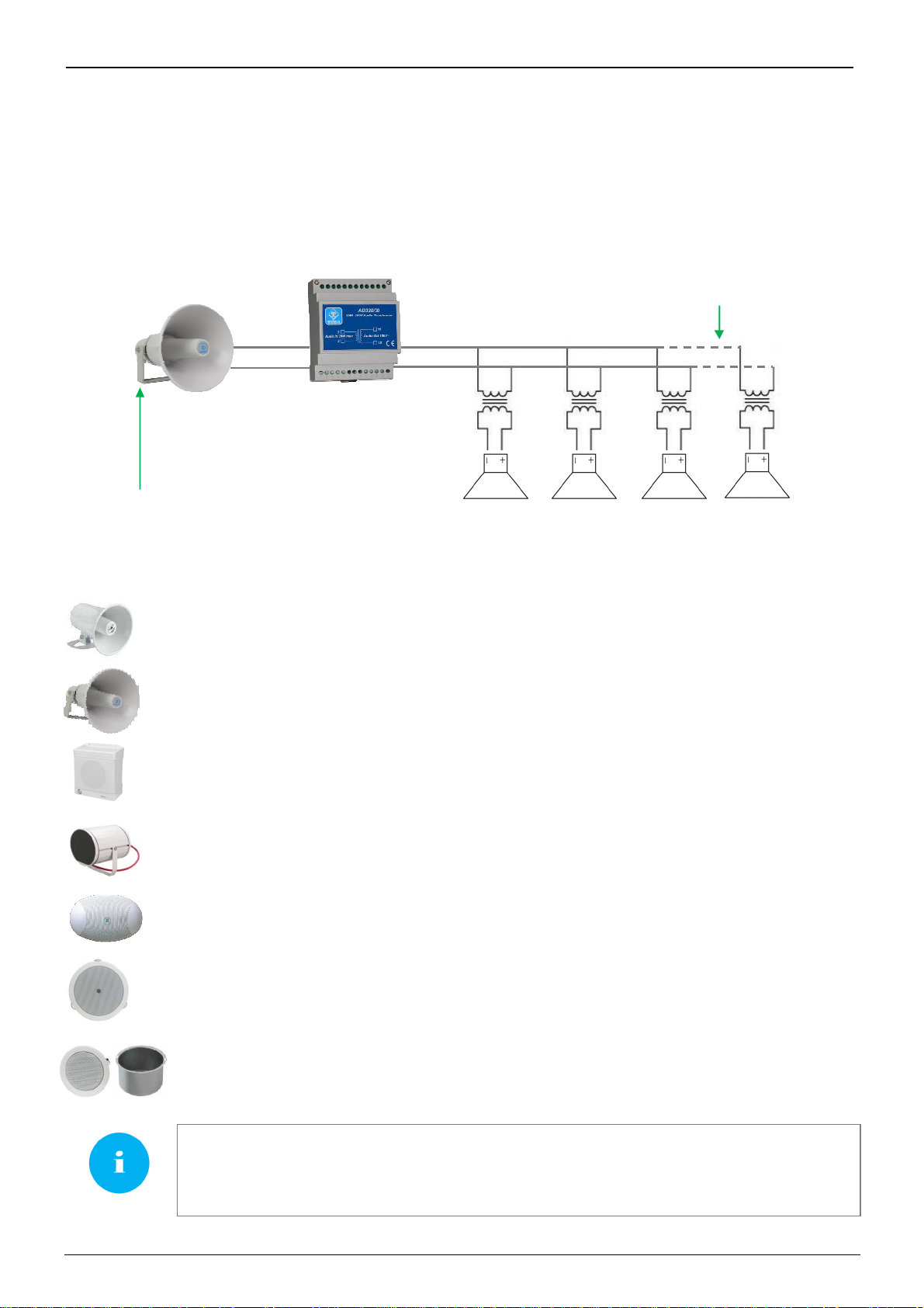
8.5. 100V audio line for additional speakers awayfrom AD630 IP Horn
For special applications it is possible to generate from AD630 an audio line at a constant voltage of 100V of max
20W power using a Tema AD320/30 transformer to connect on the SP1 power output. In this way it is possible to
install several other additional speakers (with internal transformer suitable for 100V line and selectable power) even
at distances up to 200 meters from AD630. The total sum of the power the installed speakers must not exceed the
maximum power of 20W.
Some examples of speakers available on Tema catalog (not amplified, passive models)
AD330/15T Horn Speaker 15W / 8Ohm with transf. 100V, sockets 15/7.5/3.7/1.9 W
response 300Hz - 7KHz, Dim. Diam. 210 x 240 mm
AD330/25T Horn Speaker 25W / 8Ohm with transf. 100V, sockets 25/12.5/6.25/3.12W
response 300Hz - 7KHz, Dim. Diam. 240 x 290 mm
AD335/06TP Wall Speaker 6W / 8Ohm Transf. 100V sockets 6/3/1.5 W
response 180Hz- 16KHz, Dim. 218 x 216 x 120 mm
AD334/20TP Vandal proof Projector 20W with transf. 100V, outdoor, sockets 20/10/5 W, IP65
response 150Hz - 15KHz, Dim. Diam. 180 x 145 mm, weight 2.4kg, grey color
AD337/06TP Oval wall speaker 6W / 8Ohm with transf. 100V sockets 6/3/1.5W
response 180Hz- 10KHz, Dim. 258 x 169 x 72 mm, 0,8Kg
AD333/12TP Round speaker wall/ceiling flush mounting, 12W with Transformer 12/6/3 W
response 80Hz - 15KHz, Dim. Diam. 200 x 62 mm(Hole 160-165mm)
D333/12XTP Round speaker ceiling flush mounting, 12W with Transf. 12/6/3 W
Band 80Hz- 20KHz, Dim. Diam. 220 x 130 mm (Hole 200-205mm)
with flameproof cover AD333/12YC
The speakers l
isted above are not produced by
TEMA, but a selection of the best third
-
parties
quality producers that are best suited to our production amplifiers and PA analog speaker
systems and IP VoIP SIP for audio LAN. The components offered however fall into the corporate
policies in terms of warranty and technical support.
100
V line
for additional speakers
AD320/30
Transformer for
100V-30W line
SP1 +
SP1
-
AD630
SIP Horn 2x20W
Minimum cable section
2 x 0,75mmq (AWG18)
2 colors or polarized strip, maximum
recommended distance 200 meters
8 Ohm
1…5W
8 Ohm
1…5W
8 Ohm
1…5W
8 Ohm
1…5W
+
-
LAN
TEMA TELECOMUNICAZIONI
AD630VoIP SIP 25W / PoE Horn
MAS-AD630-REV01EN Page 17 of 46
9. PROGRAMMING
9.1. Preparation for the system parameters programming
Programming is done via the WEB interface. To gain access, simply connect an Ethernet cable froma PC or froma
switch to the LAN port of AD630.
The default IP address of AD630 is "192.168.0.10".
Remember that in order to successfully connect to the web interface of AD630, it is necessary that, in the IP
addresses configuration of your PC, is present the subnet 192.168.0.x, where "x" is any number between 1 and
254 and different from 10. See below how to configure your PC to reach the correct subnet. The shown procedure
applies to Windows® operating systems.
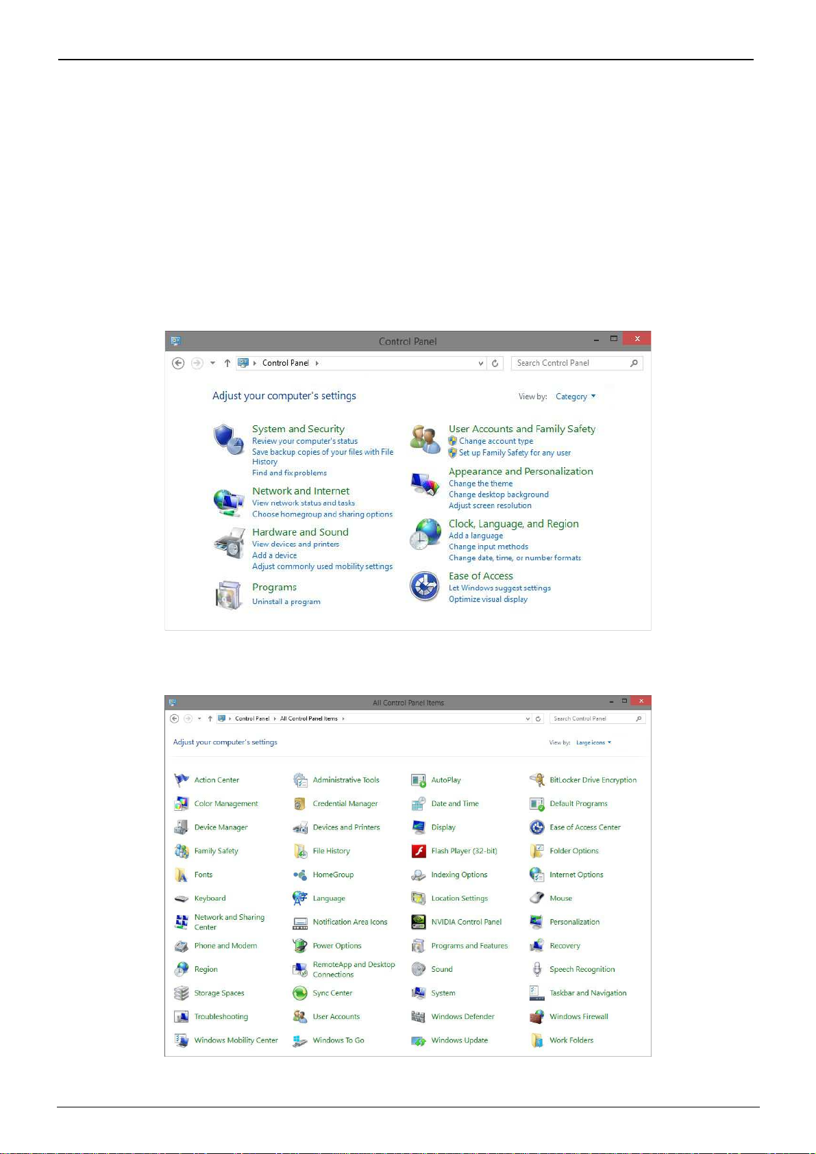
Open the Windows Control Panel and set the field "View by": "Category" "Large Icons" or "Small Icons".
Choose "Network and Sharing Center" as shown in the first figure, detect your LAN connection, choosing the one
referring to the network card that you are using to connect with AD630.
TEMA TELECOMUNICAZIONI
AD630VoIP SIP 25W / PoE Horn
MAS-AD630-REV01EN Page 18 of 46
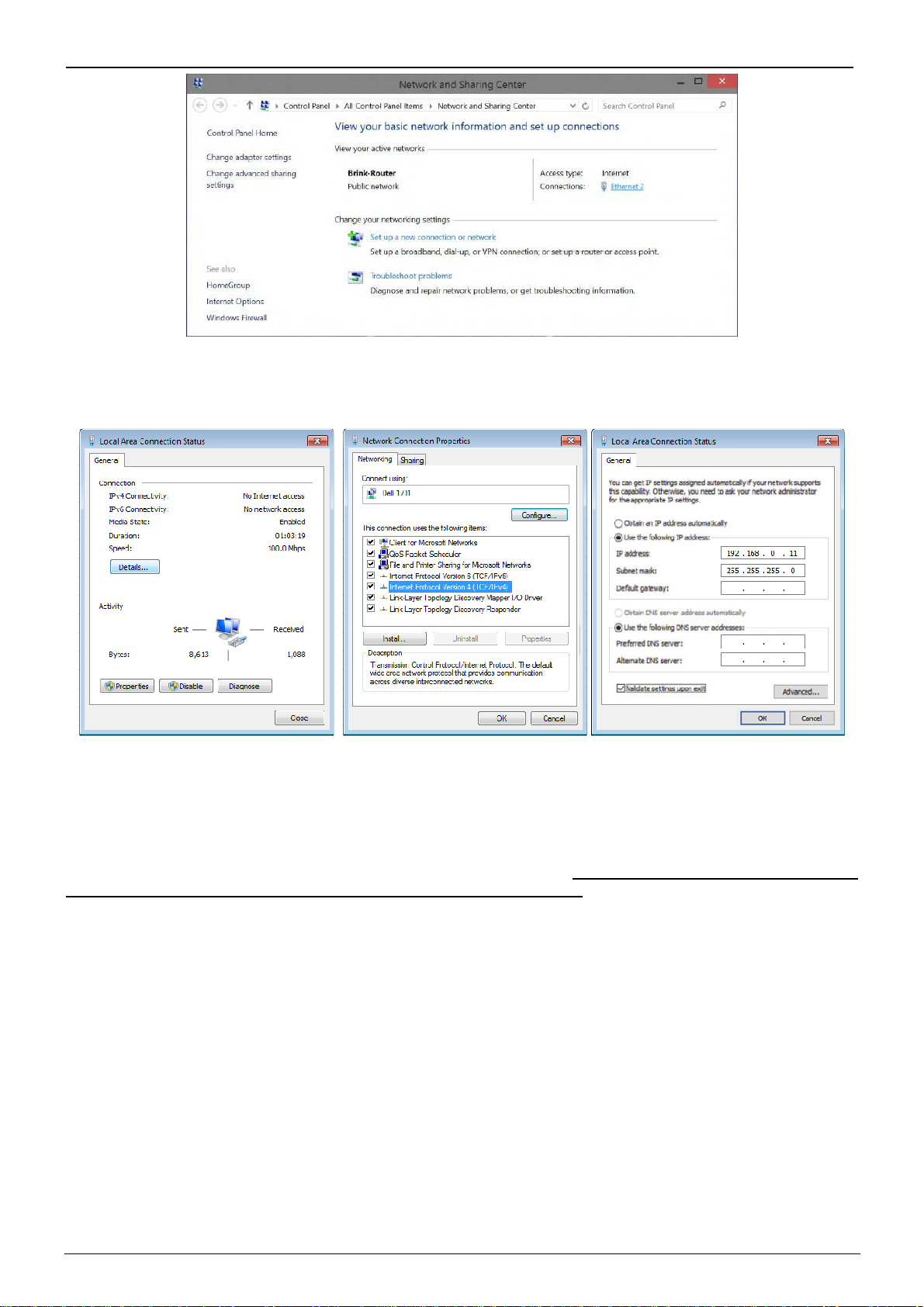
Once the correct connection is identified, click on it and it will appear the window where it is necessary to click on
the "Properties" button. It will then open the window where must be selected "Internet Protocol Version 4
(TCP/IPv4)" and then click the Properties button again. See the following figures:
If the PC is already on subnet 192.168.0.x with a mask 255.255.255.0, ignore the following steps. Otherwise,
proceed as follows. (The address of the PC configuration should not be 192.168.0.10). Remember the current
TCP/IP configuration of your computer for any subsequent restore of the correct parameters. Click "Use the
following IP address" and type in the appropriate field the following IP address: 192.168.0.11 (instead of "11" used
in the example it is possible to enter any number between 1 and 254, but excluding the 10 which is the default
address of the system to be programmed). In the "Subnet Mask" enter the netmask 255.255.255.0. Click OK to
confirm the changes. The PC is now ready to configure the door phone. Remember at the end of programming to
restore the network configuration of the PC to its original state if necessary.
Once the IP address of your PC is successfully configured, it is possible to reach the Web interface to configure
AD630 at the address 192.168.0.10 .

TEMA TELECOMUNICAZIONI
AD630VoIP SIP 25W / PoE Horn
MAS-AD630-REV01EN Page 19 of 46
9.2. Access to programming
To program the device, it is sufficient to use a standard browser such as Explorer, Firefox, Chrome or others. The
default address of the device is 192.168.0.10 with a mask of 255.255.255.0, and the user/password with which to
connect are master/master. Make sure to have access to this network segment from your computer. Once logged
in, it is possbile to change the administrative password for the maximum safety of your device. Once logged in, it is
possbile to change the administrative password for the maximum safety of your device.
The use is very simple and intuitive, it is always visible on the left the menu for selecting the functions to be
programmed, while on the right is shown the configuration window that is currently active. Any change will be
confirmed by pressing the "Apply" or "Save" buttons. Closing the browser or changing the page without selecting
those buttons will make lost any change
.
Any changes do not require restarting the device (except the change of IP address, and the software update).

TEMA TELECOMUNICAZIONI
AD630VoIP SIP 25W / PoE Horn
MAS-AD630-REV01EN Page 20 of 46
9.3. Network parameters
On this page it is possible to set the network parameters, such as IP address, netmask, etc.:
The default IP address of the device is 192.168.0.10 . Gateway and DNS are only needed if you want the device to
have the ability to access the Internet (for example to get the current date / time, in the example from the site
time.nist.gov).
The changes to the network settings are taken over by the device until the next reboot. Once you have completed
the configuration steps so be sure to reboot the system and if necessary, change the network segment of your
computer so that it can connect to the new address.
•IP address: specify the IP address you want to assign to AD630.
•Subnet mask: indicate the subnet mask to be assigned to AD630.
•Default gateway: indicate the gateway that can enable AD630 to access to internet.
•Primary and secondary DNS server: indicate the addresses of two DNS servers you want to use to resolve
IP addresses.
•Time server: indicate the address of the server you want to use for time synchronization device.
•Test address (ping): if inserted, this address is used by the system to verify the correct operation of the
network connection.
•SMTP server: name or IP address of the mail server.
•Port: TCP port for the connection. Usually is 25
•User: authenticated user on the SMTP server
•Password: SMTP authentication password
•TLS connection: activate the secure connection
•Destination: email destination
•Text message: text to be included in the email sent
The button “Test Mail” can be used to test immediately if the configuration works.
Table of contents


