Temescal FC-3800 User manual

FACILITY AND INSTALLATION GUIDE FOR
FC-3800 EVAPORATION SYSTEMS
Temescal, a division of Ferrotec (USA) Corporation
4569-C Las Positas Road, Livermore, CA 94551
Tel: 1-800-522-1215; Fax: 925-449-4096
0101-8604-0
Revision F, March 2011

Revision History
0101-8604-0
Revision Change Description Reason/
Application Date Approved
A First version of F & I Guide Applies to all FC-3800
systems built between
2/2000 and 6/2006
Feb.
2000
GW
B Added illustrations to Section 3 Applies to all FC-3800
systems built after 6/2006
July
2006
SS
C Revised instructions for installing
external transformer in nominal 400
V installations (see section 3.2.4)
Applies to all FC-3800
systems build after 6/2006
July
2006
SS
DRevised sections 1.4, 2.2.1, and
3.2.7. Modified Figures 3-4 through
3-14.
Clarified specifications and
instructions regarding water
supplies #2 and #3.
Nov.
2006
SS
E In sections 1.4 and 2.5, corrected
values for power drops to be
provided for vacuum system and e-
beam power supplies. Added Figure
2-3 and updated Figure 3-2. Deleted
former Figures
3-7, 3-9, and 3-11.
Corrections provided by
Temescal Field Service
and Temescal Engineering.
Eliminated former Simba 2
control console option.
Oct.
2010
LW
F In sections 1.4 and 2.4, corrected
input power specifications for
vacuum system.
Updated information
provided by Temescal Field
Service.
March
2011
LW
© 2011 Ferrotec (USA) Corporation. All rights reserved.

0101-8604-0, Rev. F i FC-3800 F & I Guide
TABLE OF CONTENTS
Section Page
Table of Contents......................................................................................... i
Safety Instructions for Operating and Service Personnel ............................ iii
Special Amendment for U.K. Users: Electrical Safety Precautions ............. iv
User Responsibility.......................................................................................v
Guidelines and Good Practices ....................................................................v
Health Hazard ............................................................................................. vi
1 INTRODUCTION AND SITE PREPARATION CHECKLIST
1.1 Scope and Purpose of this Guide............................................................... 1-1
1.2 T emescal Contact information.................................................................... 1-1
1.3 General Safety Information......................................................................... 1-2
1.4 Site Preparation Checklist .......................................................................... 1-2
2 FACILITY REQUIREMENTS
2.1 Enviro nment ............................................................................................... 2-1
2.2 Wate r ......................................................................................................... 2-1
2.3 Compressed Gases.................................................................................... 2-2
2.4 Electrical Power Requirements .................................................................. 2-2
2.5 Electrical Grounding Requirements............................................................ 2-3
3 UNPACKING and INSTALLATION
3.1 Unpacking by Customer ..............................................................................3-1
3.2 Customer’s Site Preparation Responsibilities..............................................3-2
3.3 Temescal Installation Responsibilities.........................................................3-5
3.4 Installation Drawings ................................................................................... 3-7
LIST OF ILLUSTRATIONS
Fig. Number Page
2-1 Facility and System Grounding Requirements 2-4
2-2 Vacuum Cubicle Grounding for Simba 2 Power Supply 2-5
2-3 Low-Z Grounding Requirements on Systems with a CV-6SLX or CV-12SLX Power Supply 2-6
3-1 Elevation View of Vacuum Cubicle, Showing Vacuum Cubicle Height 3-7
3-2 System Plan View, Showing Dimensions of Main System Components 3-8
3-3 Utility Connection Points on Rear of Vacuum Cubicle 3-9
3-4 Routing of Customer-Supplied Service Lines in 208-V Installations 3-10
3-5 Routing of Customer-Supplied Service Lines in 400-V Installations 3-11
3-6 Routing of Temescal-Supplied Helium Lines to Cryopump Compressors 3-12
3-7 Routing of Control/Data Cables on Systems with the Simba 2 Power Supply 3-13
3-8 Routing of Electrical Power Cables on Systems with the Simba 2 Power Supply 3-14
3-9 Routing of EMO Cables and Copper Straps on Systems with the Simba 2 Power Supply 3-15
3-10 Routing of Power and Control/Data Cables on Systems With Either the CV-6SLX
or the CV-12SLX Power Supply 3-16
3-11 Routing of EMO Cables and Copper Grounding Straps on Systems With Either
the CV-6SLX or the CV-12SLX Power Supply 3-17

FC-3800 F & I Guide ii 0101-8604-0, Rev. F
This page intentionally left blank for pagination purposes.

0101-8604-0, Rev. F iii FC-3800 F & I Guide
SAFETY INSTRUCTIONS FOR OPERATING AND SERVICE PERSONNEL
Operators and service personnel should always wear safety glasses. Operators shall not enter areas
intended for service access only. Only experienced service personnel should enter such areas, and
only after taking the preliminary precautions described in paragraphs 1 through 6 below.
DANGER
Potentially lethal voltages may exist within this unit, even with the line power switched off.
Service should only be attempted by qualified personnel. Failure to observe all safety
precautions may result in personal injury.
This component is designed to operate as part of a system containing high-voltage equipment.
Observe the precautions described below when servicing this system, especially when servicing
components where high voltages may be present.
1. Before servicing or operating this equipment, read all the component manuals supplied with the
system, paying special attention to safety instructions.
2. Post HIGH VOLTAGE WARNING signs in conspicuous locations within the service area.
3. Remove rings, watches, bracelets, and any other metal jewelry before working around high
voltage.
4. DO NOT WORK ALONE!
5. Be sure that all equipment is connected to a power receptacle having the correct polarity and
grounding, as prescribed by the local electrical codes. Refer to the power supply portion of the
documentation to determine the proper electrical ground for high-voltage components.
6. Before servicing any high-voltage component, switch off the electrical power at the component’s
main power switch. This switch should have a lockout feature. Lock the power off and keep the
key with you while you are working on the equipment.
7. Certain electrical parts (e.g., electrolytic capacitors) hold a lethal voltage even after the power is
switched off. Before entering any service area, use a grounding hook to discharge such parts. Be
sure that these parts are discharged before starting any repairs.
8. DO NOT touch high-voltage leads unless power is off and a grounding hook is connected to the
parts to be serviced.
9. The high-voltage components of the system should be equipped with electrical interlocks to
protect personnel from injury. DO NOT ATTEMPT TO DEFEAT, OVERRIDE, OR BYPASS
THESE PROTECTIVE DEVICES!
10. Never leave loose ends on high-voltage connections.
11. Observe the following warning if the system employs Radio Frequency (RF) power.
DANGER
RF radiation—even at modest power levels—can cause serious injury. If any of the RF
components (e.g., the RF power supply, the RF matching network, or the RF electrodes or
shielding inside the product chamber) are moved or changed in any way, the RF energy may
be radiated outside the equipment. Monitor the equipment to assure that external RF
radiation is below the levels prescribed by any and all applicable safety codes.

FC-3800 F & I Guide iv 0101-8604-0, Rev. F
Special Amendment for United Kingdom Users
All Electrical Power Sources: Safety Precautions
This component is designed to be used in an extra-high-voltage system. Only authorized personnel
should be permitted to carry out work on this system.
Prior to any servicing, grounding hooks should be used to short out all high-voltage parts and
conductors in both the vacuum system and the high-voltage power supply. Screens protecting extra-
high-voltage conductors should be removed only if appropriate action has been taken to ensure that
extra-high-voltage conductors are dead and cannot be reenergized inadvertently.
In addition, all personnel should be aware of:
1. The Electricity (Factories Act) Special Regulations (1908 and 1944), in particular, Regulations
18(d) and 28 of the 1980 Regulations, as amended; and
2. The employer’s responsibility to set up suitable systems to safeguard the health and safety of
employees, according to the Health & Safety at Work etc. Act (1974).

0101-8604-0, Rev. F v FC-3800 F & I Guide
USER RESPONSIBILITY
This equipment will perform in accordance with the instructions and information contained in the
user’s manual and its referenced documents when such equipment is installed, operated, and
maintained in compliance with such instructions. The equipment must be checked periodically.
Defective equipment shall not be used. Parts that are broken, missing, plainly worn, distorted, or
contaminated, shall be replaced immediately. Should such repair or replacement become
necessary, a telephone or written request for service should be made to Temescal, Livermore, CA,
a division of Ferrotec (USA) Corp.
The equipment, or any of its parts, shall not be altered without the prior written approval of
Temescal. The user and/or purchaser of this equipment shall have the sole responsibility for any
malfunction which results from improper use, faulty maintenance, damage, improper repair, or
alteration by any party other than Temescal.
GUIDELINES AND GOOD PRACTICES
1. Follow applicable clean room procedures (smocks, masks, gloves, etc.).
2. Do not expose the vent and purge valves to excessive pressures. The nitrogen line regulator is
factory set at 15 psi and must not be adjusted above 20 psi.
3. Prevent oil, grease, water, sweat, etc. from getting into the vacuum chamber.
4. Replace the source tray shield correctly to ensure that the ceramic parts or the high voltage
feedthroughs are protected from being coated.
5. Clean all mechanical parts and seals with lint-free paper/cloth soaked with isopropyl alcohol
(IPA). Dispose all IPA-exposed cleaning paper/cloth in a fireproof container, while ensuring
proper safety precautions are being followed.
6. Polish scratched surfaces with Scotch-Brite, taking care not to produce any cross scratches.
7. Shaft seals are all ferromagnetic. No lubrication is required.
8. Check the chamber door’s seal and sealing surfaces each time before closing it.
9. Check and clean with IPA the source tray seals and sealing surfaces each time before raising
the source tray into place.
10. Train staff by competent personnel. DO NOT allow staff to operate or do maintenance and
recovery work on the machine until they are trained by competent personnel.
11. Document all alarms, deviations, breakdowns, and servicings done on either a hardcopy or an
electronic equipment-log system.

FC-3800 F & I Guide vi 0101-8604-0, Rev. F
HEALTH HAZARD
The condensates deposited on the tank walls of a vacuum system are generally in the form of
extremely fine particles. The nature, as well as the form, of the materials poses the following
potential health hazards:
a) Inhaling fine particles (powder) may cause damage to the lungs. To help prevent this, wear a
protective respirator mask with fine filter that has been approved by the National Institute for
Occupational Safety and Health (NIOSH) and the federal Mine Safety and Health
Administration (MSHA).
b) Some substances are toxic and inhaling them should be avoided. Take steps to ascertain
whether or not the material being deposited is a known toxic substance. Refer to the Material
Safety Data Sheet(s) covering the evaporant(s) in question.
c) Certain powders (titanium, for instance) can cause flash fires when exposed to oxygen or
other oxidizers. Therefore, when opening the chamber door after a deposition cycle, exercise
extreme caution and allow time for the coating surface to oxidize. Breakage of some of the
more reactive condensates may be hazardous, even when the above precautions are observed.
In this situation, fire-protective clothing should be worn.
d) Certain powders (platinum, for instance) are known to catalyze methyl alcohol vapors upon
contact, generating heat in the process and possibly causing a fire to erupt. Therefore, never
use methyl alcohol to wipe down or clean any internal tank surfaces of a vacuum system.
Use isopropyl alcohol (IPA), instead. Dispose of all IPA-exposed lint-free paper/cloth into a
fireproof container, while ensuring all proper safety procedures and precautions are being
followed.

0101-8604-0, Rev. F vii FC-3800 F & I Guide
Customer
Documentation
Survey
In an effort to provide continuous improvement and ensure technical accuracy regarding product
documentation, we invite you to comment on this Facilities & Installation (F & I) Guide.
Please fill out and return this form to Temescal as soon as possible. Thank You.
Company: __________________________________________ Today’s Date: _____________
System Ordered: _____________________________________ Delivery Date: _____________
1. Please rate the quality of the information provided using the following rating system:
1 = Poor 2 = Fair 3 = Acceptable 4 = Good 5 = Excellent
Site preparation checklist 12345
Descriptions of facility requirements 12345
Installation instructions 12345
Installation drawings 12345
2. Was the information in this manual clearly presented and easy to understand?
YES NO
If NO, please cite specific references: _____________________________________
____________________________________________________________________
3. Did you find errors in this manual? YES NO
If YES, typographical or technical? (please cite the pages)
____________________________________________________________________
4. How important was this F & I Guide in preparing for your system (circle one)?
Essential Important Nice to Have Not Important
5. Do you currently own and operate any other Temescal Systems? YES NO
(please specify) ______________________________________________________
6. What kind of information would you like to see in future F&I Guides?
____________________________________________________________________
____________________________________________________________________
7. Do you have any additional comments/suggestions/complaints? If so, please explain:
____________________________________________________________________
____________________________________________________________________
Name: __________________________________ Telephone: ______________________
Fax #: __________________________________ E-mail: __________________________
Thank you for taking the time to review our documentation. Please mail or fax this form back to:
Temescal, a division of Ferrotec (USA) Corp.
Attn: Customer Support
4569-C Las Positas Road, Livermore, CA 94551
Telephone: 1-800-522-1215 Fax: 925-449-4096

FC-3800 F & I Guide viii 0101-8604-0, Rev. F
This page has been intentionally left blank for pagination purposes.

0101-8604-0, Rev. F 1-1 FC-3800 F & I Guide
1 Introduction and Site Preparation Checklist
1.1 Scope and Purpose of this Guide
1.1.1 Overview of F&I Guide
The purpose of this Facilities and Installation (F & I) Guide is to provide facility
requirements and installation guidelines for your Temescal System. This Guide gives
information for preparing your site to receive and install your new equipment. Topics
covered, by section, are:
Section 1: Introduction
Section 2: Facility Requirements
Section 3: Unpacking and Installation
1.1.2 In This Section
This remainder of this section covers the following topics:
1.2 Temescal Contact Information
1.3 General Safety Information
1.4 Site Preparation Checklist
1.2 Temescal Contact Information
If you have any questions or concerns, or if you need assistance, contact us at one of the
following telephone numbers:
To schedule an installation or a field service visit, call:
Customer Support Coordinator 1-800-522-1215, ext. 2817 (voice)
1-925 449-4096 (fax)
To speak with a technician, call:
Temescal Technical Support and Assistance 1-800-522-1215, ext. 2891
To order replacement or spare parts, call:
Temescal Customer Service, Parts 1-800-522-1215, ext. 2818 or 2819

Section 1: Introduction and Site Prep. Checklist FC-3800 Facility and Installation Guide
FC-3800 F & I Guide 1-2 0101-8604-0, Rev. F
1.3 General Safety Information
Specific guidelines concerning Guidelines & Practices, Operating Safety Instructions, and
warnings concerning High Voltage and Health Hazards can be found in the front of this
F&I Guide, as well as in the fronts of the Operations and Service Manuals. Additional
safety warnings may also be found in the various component manuals and third party
documentation. You will also find throughout the text of these manuals, WARNING boxes
that advise of safety concerns. An example of such a warning box appears below.
This equipment contains electrical and electronic interlocks and alarms, to protect
personnel from injury. DO NOT DEFEAT, OVERRIDE, OR BYPASS THESE
PROTECTIVE DEVICES! When the TCS is in Service Mode, numerous safety interlocks
are bypassed.
These safety warnings and notices are not only for the protection of the people who
operate or maintain the equipment, but also for the equipment itself. Failure to comply
with these safety standards can cause serious injury or death, and significant damage to
the equipment.
BEFORE OPERATING ANY EQUIPMENT, READ ALL OPERATOR MANUALS,
SAFETY NOTICES AND WARNINGS AND COMPLY WITH THEIR GUIDELINES.
1.4 Site Preparation Checklist
The customer is responsible for providing properly rated power, water, air, and gases
services to their appropriate termination points at the System prior to installation.
Specific requirements and installation specifications required for each system are
detailed in this Facilities and Installation (F&I) Guide.
The customer is also responsible for meeting all applicable facility, electrical and safety
codes in routing power, water, air, and gas lines to and between the modules of the
system. For more specific details, please read the remainder of this Facilities &
Installation (F&I) Guide. If you have any questions concerning your installation, please
feel free to call Temescal Customer Support (1-800-522-1215, ext. 2891).
Please complete the Site Preparation Checklist on the next page, checking off each
requirement as it is completed. Sign and date the completed Checklist and fax it to
Temescal (925-449-4096), Attn: Customer Support Coordinator. When Temescal
receives the completed checklist, the installation date for your system will be scheduled.
WARNING
LETHAL VOLTAGES PRESENT
Residual Voltages can be present in numerous parts of the
equipment, even after the source power has been switched
off. Before touching the source tray or the electron beam gun,
you MUST use a properly connected ground hook to touch all
accessible vacuum cubicle parts that could be charged with
high voltage.

FC-3800 Facility and Installation Guide Section 1: Introduction and Site Prep. Checklist
FC-3800 F & I Guide 1-3 0101-8604-0, Rev. F
(FC-3800) SITE PREPARATION CHECKLIST
The Customer is responsible for providing properly rated power, water, air, and gases
services to their appropriate termination points at the System prior to installation. Please
read this Guide for more specific details.
As each requirement is completed, place a check mark in the appropriate check box below. When
ALL requirements have been completed, sign and date this page, then fax this checklist back to
Temescal (925 449-4096), Attn: Customer Support Coordinator.
Environment: For additional information, see section 2.1.
Ambient Air Temperature: 55ºF to 90ºF (12ºC to 32ºC),
Relative Humidity: 50% maximum
Air conditioning: Capable of 5 kW cooling
Water (conditioned): For additional information, see section 2.2.
Cold Water Supply #1 (Vacuum Cubicle)
100 psig (6.89 bar) maximum inlet pressure
50 psig (3.45 bar) minimum delta pressure
50º–70º F (10º–21º C) maximum inlet temperature
Filtered to 50 microns
Flow Rate Requirements:
Chamber walls and doors 6.0 gpm (22.7 L/min.)
Each e-beam source 2.75 to 5.0 gpm (10.4 to 18.9 L/min.)
5-cm ion beam source 0.5 gpm (1.9 L/min.)
Each crystal monitor 0.5 gpm (1.9 L/min.)
Cold Water Supply #2 (Cryopump Compressors)
Min./max. inlet pressure 30/100 psig (2.07/6.89 bar)
Inlet temperature 10º–30º C
Min. flow rate 2.75 gpm (10.4 L/min.) for each
compressor
Cold Water Supply #3
For Edwards Model iGX100 and iGX3/100 pumps:
Min./max. inlet pressure 40/100 psig (2.77/6.89 bar)
Inlet temperature 10º–30º C
Min. flow rate requirements
Edwards Model iGX100 0.3 gpm (1.1 L/min.)
Edwards Model iGX3/100 0.6 gpm (2.2 L/min.)
For water requirements for mech. pumps other than those supplied
by Temescal, consult the manufacturer of the pump in question.
Optional Hot Water
90 psig (6.21 Bar) maximum inlet pressure
50 psig (3.45 Bar) minimum delta pressure
5 gpm (18.9 L/min.) flow rate
140° F (60° C) approximate temperature
Filtered to 50 microns

Section 1: Introduction and Site Prep. Checklist FC-3800 Facility and Installation Guide
FC-3800 F & I Guide 1-4 0101-8604-0, Rev. F
Compressed Gases: For additional details, see section 2.3.
Vent Gas: Clean Dry Air (CDA) and/or Nitrogen (N2) (recommended)
60 to 120 psig (4.14 to 8.27 bar)
Pneumatic Air: 90 to 120 psig (6.21 to 8.27 bar)
Helium: One bottle, 99.999% pure.
Optional Process Gas: Argon, 99.995% minimum purity
3 to 3 sccm (for FC ion beam source without PBN) or
5 to 8 sccm (for FC beam ion source with PBN)
Electrical: For additional information, see sections 2.4 and 2.5.
Ground: Good earth ground, low impedance to RF as well as DC. For illustrations
and additional details, see section 2.4.
Main System (Drop #1)
208 VAC, 60 Hz, 3-phase 4-wire, 150 A
or
400 VAC, 50 Hz, 3-phase 4-wire, 90 A
HV Power Supply (Drop #2) (Select one power supply only)
Simba 2 208/240 VAC, 50/60 Hz, 3-phase delta, 4-wire, 90 A
Simba 2 380 VAC, 50/60 Hz, 3-phase delta, 60 A current)
Simba 2 480 VAC, 50/60 Hz, 3-phase delta, 50 A
CV-6SLX 208 VAC, 50/60 Hz, 3-phase 4-wire, 30 A
CV-6SLX 400 VAC, 50/60 Hz, 3-phase 5-wire delta, 20 A
CV-12SLX 208 VAC, 50/60 Hz, 3-phase 4-wire, 50 A
CV-12SLX 400 VAC, 50/60 Hz, 3-phase 5-wire delta, 30 A
Site Preparation and Installation Instructions: Section 3 of this F&I Guide has
been read and understood.
Customer: _______________________________________ Date: __________________
Company: _______________________________________ System: ________________

0101-8604-0, Rev. F 2-1 FC-3800 F & I Guide
2 Facility Requirements
This section of the Guide specifies the requirements for the various facilities services,
including:
Environment (subsection 2.1)
Water (subsection 2.2)
Compressed gases (subsection 2.3)
Electrical power (subsection 2.4)
Electrical grounding (subsection 2.5)
The customer is responsible for properly preparing the site for the delivery, installation,
and operation of the system ordered. Site preparation includes providing properly rated
power, water, air, compressed gases to their appropriate facility termination points.
Before system installation can be scheduled, site preparation must be completed, and the
Site Preparation Checklist (see Section 1.4) must be completed and returned to
BOCE/Temescal.
2.1 Environment
Ambient Air Temperature: 55º F to 90º F (12º C to 32º C)
Relative Humidity: 50% maximum; must be free of corrosive fumes and vapors
Air Conditioning: Capable of 5 kW cooling
2.2 Water
Both cold and hot water must be filtered to 50 microns. In addition, the water supplied to
the system must have a ph level of between 6.0 and 8.0. To prevent hard water deposits,
it must be conditioned to maintain a calcium carbonate (CaCo3) content of less than 75
ppm. Actual water-flow requirements may vary, depending on your system and its
components.
2.2.1 Cold Water
Note: Condensation on water lines can impair the performance of the
equipment and cause damage. Therefore, the cold water temperature should
not exceed the dew point.
Cold Water Supply #1 (Vacuum cubicle)
Filtered to 50 microns
Maximum inlet pressure 100 psig (6.89 bar)
Minimum delta pressure 50 psig (3.45 bar)
Maximum inlet temperature 68° F (20º C)
Flow Rate Requirements
Chamber walls and doors 5 gpm (18.9 L/min)
Each e-beam source 2.75 to 5 gpm (11.4 to 18.9 L/min)
5-cm ion beam source 0.5 gpm (1.9 L/min)
Each crystal monitor 0.5 gpm (1.9 L/min.)

Section 2: Facility Requirements FC-3800 Facility and Installation Guide
FC-3800 F & I Guide 2-2 0101-8604-0, Rev. F
Cold Water Supply #2 (Cryopump Compressors)
Min./max. inlet pressure 30/100 psig (2.07/6.89 bar)
Inlet temperature 10º–30º C
Min. flow rate 2.75 gpm (10.4 L/min.)
Cold Water Supply #3
For Edwards Model iGX100 and iGX3/100 pumps:
Min./max. inlet pressure 40/100 psig (2.77/6.89 bar)
Inlet temperature 10º–30º C
Min. flow rate requirements
Edwards Model iGX100 0.3 gpm (1.1 L/min.)
Edwards Model iGX3/100 0.6 gpm (2.2 L/min.)
Regarding water requirements for mechanical pumps other than
those supplied by Temescal, consult the specific pump manufacturer.
2.2.2 Optional Hot Water
5 gpm (18.9 l/min) flow rate
90 psig (6.21 bar) maximum inlet pressure
50 psig (3.45 bar) minimum delta pressure
140º F (60º C) approximate temperature
Filtered to 50 microns
Note: Hot water must not be hot enough to cause scalding or burning
to the touch.
2.3 Compressed Gases
2.3.1 Vent Gas (for process and/or purging): Clean Dry Air (CDA) or Dry Nitrogen (N2)
60 to 120 psig (4.14 to 8.27 bar)
Note: To minimize pressure fluctuations in the system, a vent gas
supply pressure of 60 to 120 psig is recommended. The actual
venting pressure within the system is lower. The FC-3800 system
features built-in regulation to reduce this pressure as required.
2.3.2 Pneumatic Air (oil free) for activation of valves: 90 to 120 psig (6.21 to 8.27 bar)
2.3.3 Helium: One bottle, 99.999% pure (For additional details, see section 3.3.1.)
2.3.4 Optional Process Gas: Argon (99.99% minimum purity)
3 to 5 sccm, for FC ion beam source without PBN, or
5 to 8 sccm, for FC ion beam source with PBN
2.4 Electrical Power Requirements
The Customer is responsible for providing reliable electrical power to supply the
requirements of the system ordered. The facility’s operating voltage must be specified
when the equipment is purchased. Main system power (Drop #1) and high-voltage power
(Drop #2) must be properly connected to the power distribution box prior to the actual
system installation. Circuit breakers must be of a type designed to handle the currents
indicated. General power requirements are as specified below. Actual requirements may
vary, depending on system accessories and options.
2.4.1 Drop #1 (Main System): (15 kVA)
208 VAC, 50/60 Hz, 3-phase 4-wire wye, 150 A
400 VAC, 50/60 Hz, 3-phase 4-wire wye, 90 A

FC-3800 Facility and Installation Guide Section 2: Facility Requirements
0101-8604-0, Rev. F 2-3 FC-3800 F & I Guide
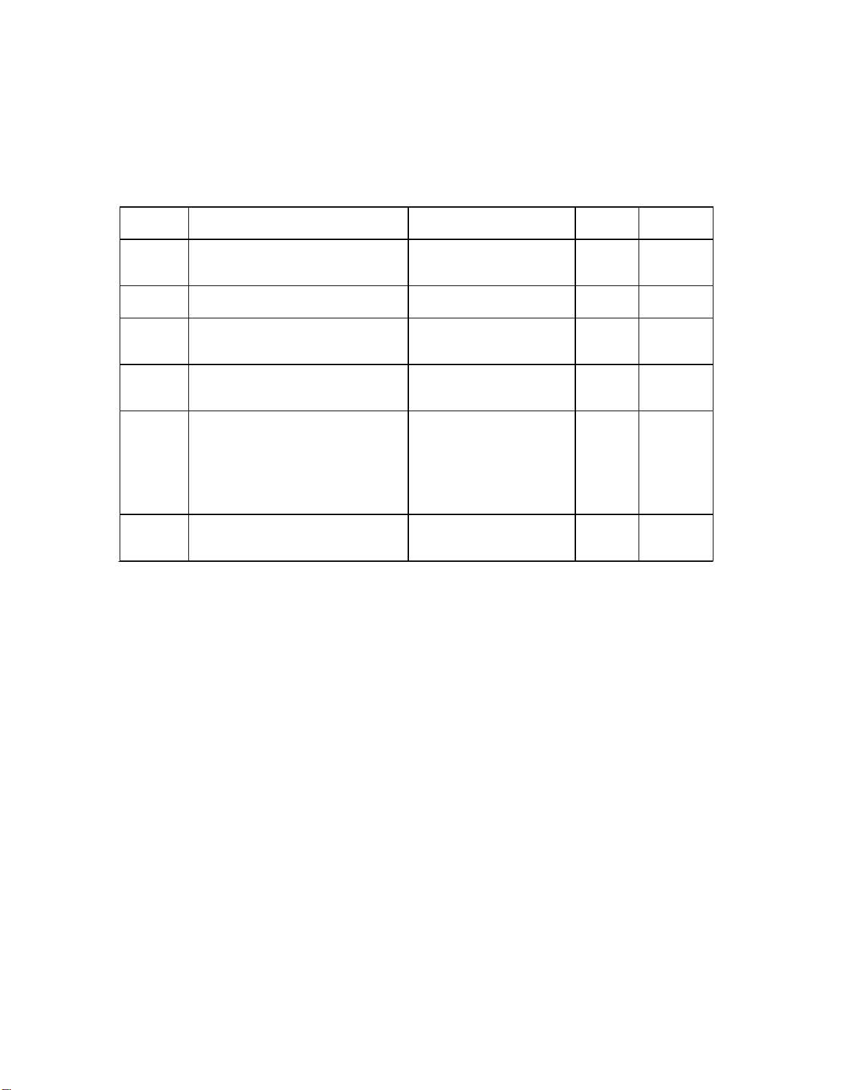
2.4.2 Drop #2 (High Voltage Supply):
Simba 2® Power Supply (15 kVA)
208-220 VAC, 50/60 Hz, 3-phase 4-wire, 90 A
380 VAC 50/60 Hz, 3-phase 5-wire wye, 60 A
480 VAC, 50/60 Hz, 3-phase 5-wire delta, 50 A
CV-6SLX Power Supply (6 kVA)
208 VAC, 50/60 Hz, 3-phase 4-wire, 30 A
400 VAC, 50/60 Hz, 3-phase 5-wire wye, 20 A
CV-12SLX Power Supply (12 kVA)
208 VAC, 50/60 Hz, 3-phase 4-wire, 50 A
400 VAC, 50/60 Hz, 3-phase 5-wire wye, 30 A
2.5 Electrical Grounding Requirements
2.5.1 System Low Impedance Ground.
Safe, dependable operation of the HV power supply cannot be ensured unless a good
earth ground is provided for the system and the power supply. This ground must provide
a low-impedance path for radio frequency (RF) and direct current (DC) electricity. This
ground must not be connected to that of any other system or equipment.
Figure 2-1 illustrates the required facility and system grounding requirements. Two 8-foot
(2.44-meter) copper-clad steel rods of ¾ inch (20 mm) diameter should be driven into the
earth as near as possible to the vacuum cubicle. These rods should be approximately 6
feet (1.85 meters) apart. After they are driven into the ground, the resistance between
them should be measured with an accurate volt-ohm meter. The maximum allowable
resistance is 3 ohms. If the resistance is greater than that value, pouring salt water or
copper sulfate down the sides of the rods may lower the resistance to the required level.
To ensure a low-impedance path to ground, the rods must be connected to each other
and to the vacuum chamber by a length of 3-inch (76-mm) wide copper strap. For runs of
less than 60 feet (18.3 meters), this strap should be 0.035 to 0.050 inches (0.9–1.3 mm)
thick. For runs longer than 60 feet, consult Temescal for specifications. The strapping
should be silver-soldered to one of the rods and secured to the other mechanically, so
that the grounding strap can be disconnected later to allow retesting of the resistance
between the rods. The other end of the grounding strap should be connected with a
grounding lug or bolt to the evaporation system’s central grounding point, an area of
clean bare metal on the vacuum cubicle wall or frame.
If the equipment is to be installed on the upper floors of a building, the system can be
grounded by connecting the vacuum chamber to the steel structure of the building. This
connection should also be made with 3-inch (76-mm) copper strapping of the gauge
specified above. Figure 2-1 also shows this alternative method.
CAUTION
Do not use braided wire for any ground connections.
CAUTION
Do not rely on water pipes to establish the system ground
connection. Multiple plumbing joints, each with tape and/or
sealing compounds, make such a ground unreliable.

Section 2: Facility Requirements FC-3800 Facility and Installation Guide
FC-3800 F & I Guide 2-4 0101-8604-0, Rev. F
Figure 2-1 Facility and System Grounding Requirements

FC-3800 Facility and Installation Guide Section 2: Facility Requirements
0101-8604-0, Rev. F 2-5 FC-3800 F & I Guide
2.5.2 Low-Impedance Ground for the E-Beam Power Supply
Figure 2-2 illustrates the grounding requirements for the Simba 2 power supply. A length
of 3-in.-wide copper strap must connect the Simba 2 power module to the system’s
central grounding point. In addition, the shield of the high-voltage cable running between
the gun interface and the filament transformer must be connected to the vacuum
cubicle’s central grounding point, as shown in Figure 2-2. The gun interface chassis must
also be connected to the system’s low-impedance ground. If the gun interface is mounted
in the optional control console, the gun interface can be grounded in one of two ways. A
length of copper strap can connect its grounding lug directly to the system’s central
grounding point, as indicated in Figure 2-2. Alternatively, a short length of copper strap
can be used to connect grounding lug on the gun interface to the grounding bracket on
the Simba 2 power module, as indicated in Figure 3-9. If the gun interface is mounted in
the operator station, its low-impedance ground is provided by the length of copper strap
that connects the operator station to the system’s central grounding point.
Figure 2-2 Vacuum Cubicle Grounding for Simba 2 Power Supply
On systems with CV-6SLX and CV-12SLX power supplies, the power module is mounted
in the operator station, so its low-impedance ground is likewise provided by the length of
copper strap that connects the operator station to the system’s central grounding point.
On these power supplies, the high-voltage cable connecting the power module to the
filament power supply (FPS) is adequately grounded when the coaxial cable is plugged
into the FPS. For an illustration of the low-impedance grounding requirements on
systems with a CV-6SLX and a CV-6SLX power supply, see Figure 2-3.

Section 2: Facility Requirements FC-3800 Facility and Installation Guide
FC-3800 F & I Guide 2-6 0101-8604-0, Rev. F
Figure 2-3 Low-Z Grounding Requirements on Systems Equipped
with a CV-6SLX or CV-12SLX Power Supply
2.5.3 Electron Beam Source Ground
To ensure a good ground between the electron beam source and the vacuum cubicle, the
following conditions must be met:
The base of the source and the surface on which it is mounted (usually the upper
surface of the source tray) must be clean and free of evaporated material.
The mounting surface must be made of nonmagnetic material.
The source must be securely bolted to the mounting surface.
2.5.4 Grounding Hooks
One grounding hook is provided at each of the following locations of the system where
high voltage may be present:
Inside the vacuum cubicle
On systems with CV-6SLX or CV-12SLX power supplies, inside the right-hand
door of the operator station
On systems with Simba 2 power supplies, on the side of the Simba 2 power
module
Table of contents
Popular Heat Pump manuals by other brands

Gree
Gree Versati II Series Service manual

Mitsubishi Electric
Mitsubishi Electric City Multi PMFY Series Technical & service manual

Lennox
Lennox INNOV DM R Series Application guide

evoheat
evoheat EVO COMMAND Series manual

Carrier
Carrier Comfort 25HCD4 Advance product data

Dimplex
Dimplex LA 6MR Installation and operating instrictions

Johnson Controls
Johnson Controls RL Series Installation operation & maintenance

Carrier
Carrier 50HS024-060 Installation, Start-Up and Service Instructions

Dimplex
Dimplex LA 9TU Installation and operating instructions

CIBIN
CIBIN KUMA manual

Daikin
Daikin EKHBRD011AAV1 installation manual

Trane
Trane CXAO Installation operation & maintenance