Temp-Heat THP-750 Manual

Installation and Service Manual
1-800-836-7432
Temporary
Heating
Cooling
Dehumidifying
Ventilating
For your safety,
do not use this heater in a
space where gasoline or
other liquids having
flammable vapors are
stored or used.
This manual is the property of the
owner. Leave with the unit when
set-up and start-up are complete.
THP-750
Gas, Direct-Fired Temporary Heater
Warning . . . . . . . . . . . . . . . . . . . . . . . . . . . . . . . . . . . . . . . . . . . . . . . . . . . . . .3
Introduction . . . . . . . . . . . . . . . . . . . . . . . . . . . . . . . . . . . . . . . . . . . . . . . . . . .4
Rating Information . . . . . . . . . . . . . . . . . . . . . . . . . . . . . . . . . . . . . . . . . . . . . .5
Control Functions . . . . . . . . . . . . . . . . . . . . . . . . . . . . . . . . . . . . . . . . . . . . . . .6
Fuel Supply System — Bulk-Tank System . . . . . . . . . . . . . . . . . . . . . . . . . . .7
Natural-Gas Installations . . . . . . . . . . . . . . . . . . . . . . . . . . . . . . . . . . . . . . . . .8
Set-Up . . . . . . . . . . . . . . . . . . . . . . . . . . . . . . . . . . . . . . . . . . . . . . . . . . . . . . .9
Preliminary Start-Up Steps . . . . . . . . . . . . . . . . . . . . . . . . . . . . . . . . . . . . . .10
Control Vestibule Layout . . . . . . . . . . . . . . . . . . . . . . . . . . . . . . . . . . . . . . . .11
Start-Up Steps . . . . . . . . . . . . . . . . . . . . . . . . . . . . . . . . . . . . . . . . . . . . . . . .12
Shut-Down Steps . . . . . . . . . . . . . . . . . . . . . . . . . . . . . . . . . . . . . . . . . . . . . .13
Short-Term . . . . . . . . . . . . . . . . . . . . . . . . . . . . . . . . . . . . . . . . . . . . . . . .13
Long-Term or Disconnect . . . . . . . . . . . . . . . . . . . . . . . . . . . . . . . . . . . . .13
Wiring Sequence of Operation . . . . . . . . . . . . . . . . . . . . . . . . . . . . . . . . . . . .14
Troubleshooting . . . . . . . . . . . . . . . . . . . . . . . . . . . . . . . . . . . . . . . . . . . . . . .16
Control Adjustments . . . . . . . . . . . . . . . . . . . . . . . . . . . . . . . . . . . . . . . . . . . .19
Ignition . . . . . . . . . . . . . . . . . . . . . . . . . . . . . . . . . . . . . . . . . . . . . . . . . . .19
Airflow Control . . . . . . . . . . . . . . . . . . . . . . . . . . . . . . . . . . . . . . . . . . . . .19
Setting Control . . . . . . . . . . . . . . . . . . . . . . . . . . . . . . . . . . . . . . . . . .19
To Check Setting . . . . . . . . . . . . . . . . . . . . . . . . . . . . . . . . . . . . . . . . .19

3
TEMP-HEAT
®
This heater is designed and approved for use as a construction heater under ANSI Z83.7-1990.
We cannot anticipate every use which may be made of our heaters. Check with your local fire safety
authority if you have questions about applications.
Other standards govern the use of fuel gases and heat-producing products in specific applications.
Your local authority can advise you about these.
Warning
General Hazard Warning
Failure to comply with the precautions provided with this heater can result in death,
serious bodily injury and property loss or damage from hazards of fire, explosion,
burn, asphyxiation, carbon monoxide poisoning, and electrical shock.
Only persons who can understand and follow the instructions should use or service
this heater.
If you need assistance or heater information such as an instructions manual, labels,
etc., contact the manufacturer.
Fire, burn, inhalation and explosion hazard.
Keep solid combustibles, such as building materials, paper or cardboard, a safe
distance away from the heater as recommended by the instructions.
Never use the heater in spaces which do or may contain volatile or airborne
combustibles, or products such as gasoline, solvents, paint thinner, dust particles
or unknown chemicals.
Warning
Warning Not for home or recreational vehicle use.

THP-750 Installation and Service Manual
Introduction
The following recommendations are not intended to supplement requirements of federal, state, or local
codes having jurisdiction over the application and operation of this heater.
This instruction booklet contains the necessary information, instructions, and guidelines to achieve
maximum efficiency and safety from the TEMP-HEAT construction heater. Please read all instructions
before attempting the set-up and operation of this heater.
The THP-Series Heaters are direct-fired, fresh-air heaters used to provide temporary heat for buildings
under construction, alteration, or repair. The area of fresh air required for safe operation must be equal to
the area of the unit’s intake grill. THP-Series heaters draw fresh, outside air through the unit’s intake
and discharge tempered air controlled by a remote thermostat. The heaters generate 85° F to 170° F
discharge temperatures with models ranging from 300,000 BTU/hour to 4,500,000 BTU/hour operating
on natural gas or propane gas vapor.
Equipment with these characteristics are preferred for enclosed areas because they generate lower mois-
ture and contaminant levels while controlling ventilation and air distribution.
Most models are equipped with a remote thermostat and an adjustable, automatic burner control. This
combination prevents extreme temperature fluctuations that occur when ON/OFF burner controls are
selected.

5
TEMP-HEAT
®
Rating Information
snoitacificepStinU 057-PHT noitallatsniroodtuororoodniroF
MFC 000,4
ruoH/UTB muminim
mumixam
002,34
000,057
erusserPtelnI gispmuminim
saGlarutaN gispmumixam
2/1
*4
erusserPtelnI gispmuminim
enaporP gispmumixam
5
01
stnemeriuqeRlacirtcelE
spma/esahp/ztreh/egatlov
5.71/1/06/032
01/3/06/032
5/3/06/064
snoisnemiD ni,hxwxl 56x33x86
thgieW sbl056
morfecnatsidmuminiM ni,roolf
slairetamelbitsubmoc ni,pot
ni,sedis
tf,egrahcsid
0
6
6
01
snoitidnoCtneibmA muminim F
mumixam F
04-
021
tcatnoc,saglarutanisp-4revoerusserptelniroF* TAEH-PMET .

THP-750 Installation and Service Manual
Control Functions
hctiwSwolfriA nacnoitingierofebtneserpsitinuhguorhtwolfriareporptahtseifireV
.ecalpekat
rotalugeRegatS-t
sriF telniseilppusdna,erusserpetaidemretninaoterusserpknatsecudeR
.rotalugeregats-dnocesaoterusserp
lort
noCytefaS-emalF .eruliafemalffotneveehtniretaehehtnwodstuhsdnaemalfsesneS
timiLerutarepmeT-hgiH ehtnisev
lavsagsesolcdnalortnocytefas-emalfottiucriccirtcelesnepO
.noitidnocgnitaehrevonafotneve
timiLerutarepme
T-woL ehtotniriagnizeerfgnigrahcsidfoytilibissopehttsniagastcetorP
04tates-erP.etingiotsliafrenrubehttneveehtnignidliub siht,F
spordtinuehthguorhterutarepmetehtfinwodrewolbehtstuhslortnoc
.tnioptessihtwoleb
e
vlaVsaGlaunaM nwod-tuhs,mret-trohsroF.retaehtaylppusleufffostuhsyllaunaM
.ylno
hctiwSssapyBlaunaM ehtfipu
-tratsgnirudrewolbehtfonwod-tuhscitamotuaehtsedir-revO
04ehtwolebsitinuehthguorhterutarepmet -woLehtfognittesF
.lortnoctimiLerutarepmeT
evlaVlortnoCgnitaludoM .tatsomrehtetomerehtybdellortnocrenrubehtotylppu
ssagsetalugeR
evlaVtoliP.tinugnitratsnehwtolipnoitingiehtotleufseilppuS
rotalugeRegatS-dnoceS .erusserpre
nrubotslevelegats-tsrifmorferusserpteltuoehtsecudeR
kcolretnIretratS .noitisopdesolcyllamronehtnidegagn
esiretrats-rotomsevorP
tatsomrehTniatniamoterif-hgihot-wolmorfretaehehtselcycyllacitamotuA
.erutarepmetm
oorderised

7
TEMP-HEAT
®
Fuel Supply System — Bulk-Tank System
• Installation must comply with all state and local codes or, in the absence of local codes, with the
standard for the Storage and Handling of Liquified Petroleum Gases, ANSI/NFPA 58.
• Locate fuel tanks according to the minimum distances shown in the Rating Information
Table on page 5.
• The vapor-supply fuel line from the tank or vaporizer must have a first-stage regulator located
at the tank or vaporizer to reduce the tank pressure to the 10-psi needed to supply unit.
• A vaporizer may be necessary, especially on multiple-heater installations where adequate storage
supply is not attainable or practicable.
• Vaporizers must be no closer than 10-ft from a container.
• Locate vaporizers at a minimum of 15-ft from fuel-transfer valves.
Typical Vaporizer Installation — Algas 40/40 Vaporizer
union
hand valve
tee
tank fill
vapor service valve
POL connector NOTE: left-hand thread
reducer
union and UL approved 350 psi gas hose
to temporary heating unit when a vaporizer is not used
Liquid inlet line to vaporizer
must be schedule 80 black iron pipe
or copper tubing of adequate size.
Contact state or local authorities governing
the installation of vaporizers.
tee
globe valve
union
elbow
street elbow
first-stage regulator
elbow
gauge tee
tee
shut-off valve
reducer
dripleg
to temporary heating unit
first-stage regulator
yticapaCegarotShcaEyticapaCegarotShcaE yticapaCegarotShcaE yticapaCegarotShcaEyticapaCegarotShcaE dnuorGevoba ecnatsiDmuminiMecnatsiDmuminiM ecnatsiDmuminiM ecnatsiDmuminiMecnatsiDmuminiM gnidliuBmorf
knatlag-005,eno tf-01
sknatlag-0001,owtroeno tf-52
eromrolag-1002 tf-05

THP-750 Installation and Service Manual
Natural Gas Installations
• See Rating Information Table on page 5 for proper inlet pressure.
• Gas meter and supply system must be able to supply the minimum supply pressures as specified
in the Rating Information Table on page 5.
• Follow all federal, state, and local codes governing temporary-gas connections.
• Leak test all gas connections using a 1:3 solution of soap and water.

9
TEMP-HEAT
®
Set-Up
• Block heater’s wheels to prevent movement.
• Keep fresh-air intake and heated-air discharge clear of obstruction.
• Provide clearance to allow access to vestibule, blower, and motor compartments.
• Heater must be level and in compliance with minimum-clearance and minimum-distance require-
ments for combustible materials. See Rating Information Table on page 5.
• Position heater to draw 100% fresh outside air through its intake grill.
• Do not use or operate the heater in the presence of combustible vapors of liquids.
• Maintain a maximum voltage differential of plus or minus 10% while unit is running.
• Protect the hose from traffic, building materials, and contact with hot surfaces both during use
and while in storage.
• Do not move, handle, or service heater while hot, running, or connected to power supply.
• Check for gas leaks and proper functioning during installation, periodically, or when relocating.
Typical Heater Installation
from gas supply
meter
pressure gauge
regulator
manual shut-off valve
pressure gauge
regulator
discharge-air
hood extension

THP-750 Installation and Service Manual
Preliminary Start-Up Steps
• Check for proper fuel-supply application, connections, and pressure.
• Purge gas line of air, as necessary.
• Leak test all gas connections with a 1:3 solution of soap and water.
•Do not operate unit if leaks are present.
• Determine that unit is drawing 100% fresh outside air through its intake grill.
• Check for proper electrical connections and supply voltage.
• Check that the intake and discharge of unit are free from obstructions.
• Reset flame-safety control by pressing reset button on control.
• Reset motor overload.
• Check control settings:
high-temperature limit switch: 240° F
low-temperature limit switch: 40° F
THP-750 Switch Panel
low-temperature light
flame relay light
blower switch
burner switch
11
TEMP-HEAT
®
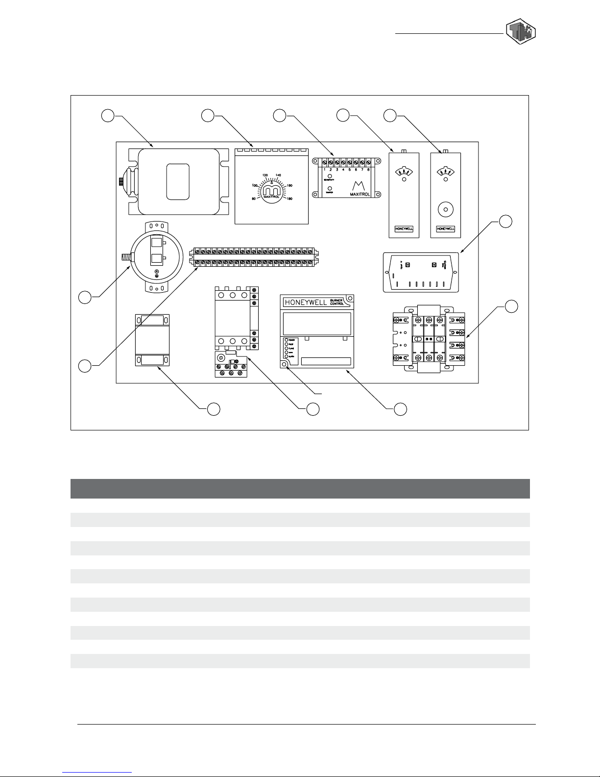
THP-750 Vestibule Layout
Control Vestibule Layout
123
45
6
7
8
910
11
12
reset
rebmuNmet
I
noitpircseD
1remrofsnartnoitingi
2 rotceleserutarepmetegrahcsid
3reifilpma
4 hctiwstimilerutarepmet-hgih
5hctiwstimilerutarepmet-hgih,teser-launam
6 hctiwstimilerutarepmet-wol
7remrofsnartrewop
8 lortnocytefas-emalf
9daolrevoretrats-rotomdnaretratsrotom
01 remrofsnartV-42
11pirtslanimret
21 hctiwswolfria

THP-750 Installation and Service Manual
Start Up Steps
1. Connect power supply. See Rating Information Table on page 5 for electrical requirements.
2. Confirm heater is set up for fuel being supplied. See Rating Information Table on page 5 for proper
gas-inlet pressures.
3. Plug remote thermostat into thermostat jack on heater. Mount in an area away from the discharge-air
stream and set at highest setting.
4. Open fuel-supply valve at tank slowly.
5. Open manual gas valve at heater.
6. Reset Flame-Safety control.
7. Check control settings:
high-temperature limit switch: 240° F
low-temperature limit switch: 40° F
8. Turn main disconnect to the ON position.
9. Turn blower and burner switches to the ON position.
For units equipped with electronic low-temperature limit control:
allows unit to run for 3-min. If discharge-sensor bulb located in the discharge-air stream does
not reach the 40° F minimum temperature, the unit shuts down, and the low-temperature bulb
glows.
To reset: turn blower and burner switches OFF. Reset the Flame-Safety Control and turn
switches back to ON.
Do not attempt to light the pilot manually.
10. Observe flame at both high- and low-fire ranges.
High Fire high-fire flame produces a discharge temperature approximating
160° F with flame extending 14-in beyond burner.
Low Fire low-fire flame produces a discharge temperature between 85° and 90° F.
11. Set remote thermostat to the desired room temperature.

13
TEMP-HEAT
®
Shut Down Steps
Short-Term Shut Down
• Turn burner switch to OFF position.
• Wait 30-sec.
• Turn blower switch to OFF position.
• Look to see that flame is extinguished.
Extended Shut-down or Disconnection of Unit
• With unit running, close vapor-fuel supply valve at vaporizer.
Caution: Do not close liquid supply valve while vaporizer is ON. See vaporizer for proper
operation of vaporizer. Contact your gas company for further information on safe handling
of propane vaporizers.
• Allow heater to run until flame-safety light goes ON, indicating that all gas has been burned
from gas lines.
Caution: Check to see that pilot light on vaporizer is extinguished before disconnecting gas lines.
• Turn burner switch OFF.
• Continue running blower until no flame exists in the base of the burner.
• Turn the blower switch OFF.
• Turn power OFF at source and disconnect electrical lines.
• Disconnect propane-vapor line from heater.
• Contact gas company to disconnect vaporizer.
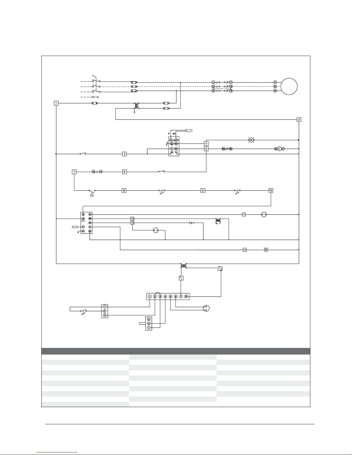
noitacifitnedItnenopmoC
10-MA reifilpma 20-NS doremalf40-SThctiwstimilerutarepmet-hgih
10-UF esufniam 10-TS retratsrotom 50-ST timilerutarepmet-hgihtenibac
20-UFesuflortnoc 50-WS hctiwsrewolb70-SThctiwstimilerutarepmet-wol
10-IL thgilerutarepmet-wol 60-WS hctiwsrenrub 80-ST erutarepmetegrahcsid-etomer
20-IL thgilteser-renrub 70-WS hctiwstrats-rewolb11-STtatsomrehtedirrevo-moor
10-TM rotomrewolb-ylppus 80-WS hctiwspots-rewolb 10-AV evlavsag-niam
10-LO daolrevoretrats 20-RT remrofsnartegatlov-wol20-AVevlavsag-niamdnoces
10-SP hctiwswolf-ria30-RTremrofsnartnoitingi 30-AV evlavsag-tolip
70-ER yalerytefas-emalf 10-ST rosnesria-egrahcsid50-AVevlavsag-gnitaludom
10-NS rosneserutarepmet-wol
230/460 VOLT
60 HERTZ
3 PHASE
POWER SUPPLY
L1
L2
L3
FU-01
FU-01
FU-01
BK
BK
BK
BK
BK
ST-01 OL-01
TS-07
TR-01 FU-03
FU-03
BK BK
BK
BK
BK
W
Y
BR
O
Y
OBL
BK R OYBL
ADD JUMPER FOR
SINGLE PHASE
SN-01
R
BR
SW-07
TS-04 TS-05
BK
BL Y
W
W
R
W
BK
BK
OR
BK
VA-01 VA-03 TR-03
VA-02
LI-02
TR-02
120V
24V BR
TS-08
AM-01
TS-01
VA-05
TS-11
BR
BK
RG YBLRO
BL
BK
RE-07
MT-01
FU-03
BK R
SW-05
ST-01OL-01
LI-01
W
W
W
W
W
W
W
Y
BR
Y
G
SN-02
BR
R
PS-01
ST-01
120V 230/460V
G
THP-750 Installation and Service Manual
Wiring Sequence of Operation
15
TEMP-HEAT
®
to 6
5
to 10
9
to 6
10
to 13
8
to 12
10
When the main safety switch, SW-01 is turned ON, power is supplied:
— to the line side of the motor starter, ST-01,
— to the primary side of the power transformer, TR-01, and
— from the secondary side of the power transformer to the FU-02 control fuse, located
on the transformer.
Terminal 1 receives 120-V power from the FU-02 control fuse.
Terminal 2 is neutral.
Terminal 3 receives power from Terminal 1 through the blower switch, SW-07
or the blower auxillary switch SW-05.
Terminal 5 receives power from Terminal 3 through the low-temperature limit
control, TS-07.
Note: the low-temperature limit control is a timed thermostat that allows the heater
to run for 3-min. If the discharge sensor bulb, located in the discharge-air stream,
does not meet the 40° F minimum temperature setting of the control, the unit shuts
down and the low-temperature alarm light, LI-01, glows.
To Reset: turn blower switch OFF, wait 45-sec and turn back ON.
Terminal 6 receives power from Terminal 5 through the burner switch, SW-06.
Terminal 7 receives power from Terminal 6 through the supply-fan motor starter.
With proper air flow through unit, Terminal 7 supplies power to Terminal 8 through
the airflow switch, PS-01.
Terminal 9 receives power from Terminal 8 through the high-temperature limit
switch, TS-04.
Terminal 10 receives power from Terminal 9 through the cabinet high-temperature
switch, TS-05.
Terminal 10 supplies power to Terminal 6 within the flame-safety control,
RE-07. Internal circuitry energizes Terminal’s 4, 8, 9 and 10 within the control.
Terminal 8 of the flame-safety control supplies power to Terminal 13, energizing the
pilot-gas valve, VA-03 and the main-gas valve, VA-01.
Note: if pilot flame is not present, the flame-safety control locks out, and the control
must be reset.
Terminal 10 of the flame-safety control supplies power to Terminal 12, energizing the
ignition transformer, TR-03.
Terminal 9 of the flame-safety control supplies power to Terminal 11, energizing the
second-main gas valve, VA-02
to 5
3
to
to
1
F2
2
13
to 11
9
to 7
6
to 8
7
to 9
8

THP-750 Installation and Service Manual
Troubleshooting
melbor
P
esuaCelbaborP ydemeR
etarepotonseodrewolBonroetauqedanI
tneserpegatlov
ebtsumV-064ot-032.tinuotylppusrewopkcehC
.5egapnoelbaTnoitamrofnIgnitaRkcehC.elbaliava
nwolbroesoolesuF .20-UF,esuflortnockcehC
tonhctiwsrewolB
noitisopNOni
.NOnruT
deppirtdaolrevorotoM .teseR
evitcefedhctiwsrewolBtaV-511rofkcehc,noitisopNOehtnihctiwshtiW
.tneserptonsiegatlovfihctiwsecalpeR.3lanimreT
nwodstuhstinU
ytefasemalfno
.lortnocnonottubtesersserP
timilerutarepmet-woL
gnittesreporptatonhctiws
nim-3:remiT
04:erutarepmeT F
dnaFF
Osehctiwsrewolbdnarenrubnrut:teseRoT
.NOkcabneht
erutarepmet-wolevitcefeD
hctiwstimil
taV-511rofkcehC.snoitcennocgniriwkcehC
.hctiwsecalper,tneserpsiegatlovonfI.5lanimreT
daolrevoretratS
evi
tcefed
.ecalpeR
rotomevitcefeD rotommorfsnoitcennocdnanoitidnocgniriwkcehC
dnaegatlovreporpgniviecersirotomfI.rotomotretrats
dnaevitcefedsirotomeht,noitidnocdoognisigniriw
.decalperebtsum
renrub,snurrewolB
etingitonseod
tonhctiwsrenruB
noitisopNOni
.NOnruT
hctiwsrenrubevitcefeD taegatlovkcehc,noitisopNOehtnihctiwsrenrubhtiW
tondna5lanimreTtatneserperaV-511fI.5lanimreT
.evitcefedsihctiwsrenrubeht,6lanimreTta
wolfriatneiciffusnI .snoitcurtsborofegrahcsiddnaekatnis'tinukcehC
.noitareporeporprofrotomdnaedalbnaftcepsnI
nosnoitcurtsniehtotgnidroccalortnocwolfriatsujdA
.91egap
.snoitcurtsboroftcepsnidnagnibutwolfriaevomeR
.gnibuttcennoceR
,8lanimreTtatontub7lanimreTtatneserpsiegatlovfI
.hctiwswolfriaehtecalper
timilerutarepmet-hgiH
tnemtsujdafotuohctiws
tuhsotseunitnoctinufI.hctiwsnonottubtesersserP
sihctiwstimilehtro,derifrevorehtiesitinueht,nwod
tcatnoC.evitcefed .TAEH-PMET
-hgihelbatsujdA
hctiwstimilerutarepmet
gnittesreporptaton
042tateS sitinueht,nwodtuhsotseunitnoctinufI.F
tcatnoC.evitcefedsihctiwstimilehtroderifrevorehtie
.TAEH-PMET

17
TEMP-HEAT
®
melbor
P
esuaCelbaborP ydemeR
renrub,snurrewolB
etingitonseod
lortnocytefas-emalF
tuokcol
tcerroctonseodgnitteserfI.lortnocnotesersserP
.lortnocytefasemalfecalper,melborp
evitcefedevlavsaG sagmorfdnaotnoitidnocdnasnoitcennocgniriwkcehC
siegatlovdnanoitidnocdoognisigniriwfI.sevlav
.tnemecalpe
rdeenyamsevlaveht,tneserp
ylppusleuFnoitamrofnIgnitaReeS.tinuotylppussagmrifnoC
.serusserpylppussagtelni
rof5egapnoelbaT
.esohsagmorfriadeelB
dorkrapsnoitingI
deppagylreporpmi
.91egapnonwohssapagni-8/1niatniaM
.dedeensadorkrapsecalpeR
seod,setingirenruB
tilyatston
evitcefeddorkrap
S dor-krapskcehC.FFOsehctiwsrenrubdnarewolbnruT
rotalusninialecroptcepsniylluferaC.noitidnocdnapag
.yrassecenfiecalpeR.erutsiomroskcarcrof
wolfriatneiciffusnI .snoitcurtsborofegrahcsiddnaekatnis'tinukcehC
.noitareporeporprofrotomdnaedalbnaftcepsnI
nosnoitcurtsniehtotgnidroccalortnocwolfriatsujdA
.91egap
.snoitcurtsboroftcepsnidnagnibutwolfriaevomeR
.gnibuttcennoce
R
,8lanimreTtatontub7lanimreTtatneserpsiegatlovfI
.hctiwswolfriaehtecalper
renrub,snurrewolB
seodtinutub,
setingi
erifhgihreviledton
ylppusleuFnoitamrofnIgnitaReeS.tinuotylppussagmrifnoC
.erusserpylppussagtelnirof5egapnoelbaT
tatsomrehtetomeR nokcajtatsomrehtotniylerucestatsomrehtetomergulP
ria-roodniehtnahtrehgiherutarepmetatateS.retaeh
.eruta
repmet
THP-750 Installation and Service Manual
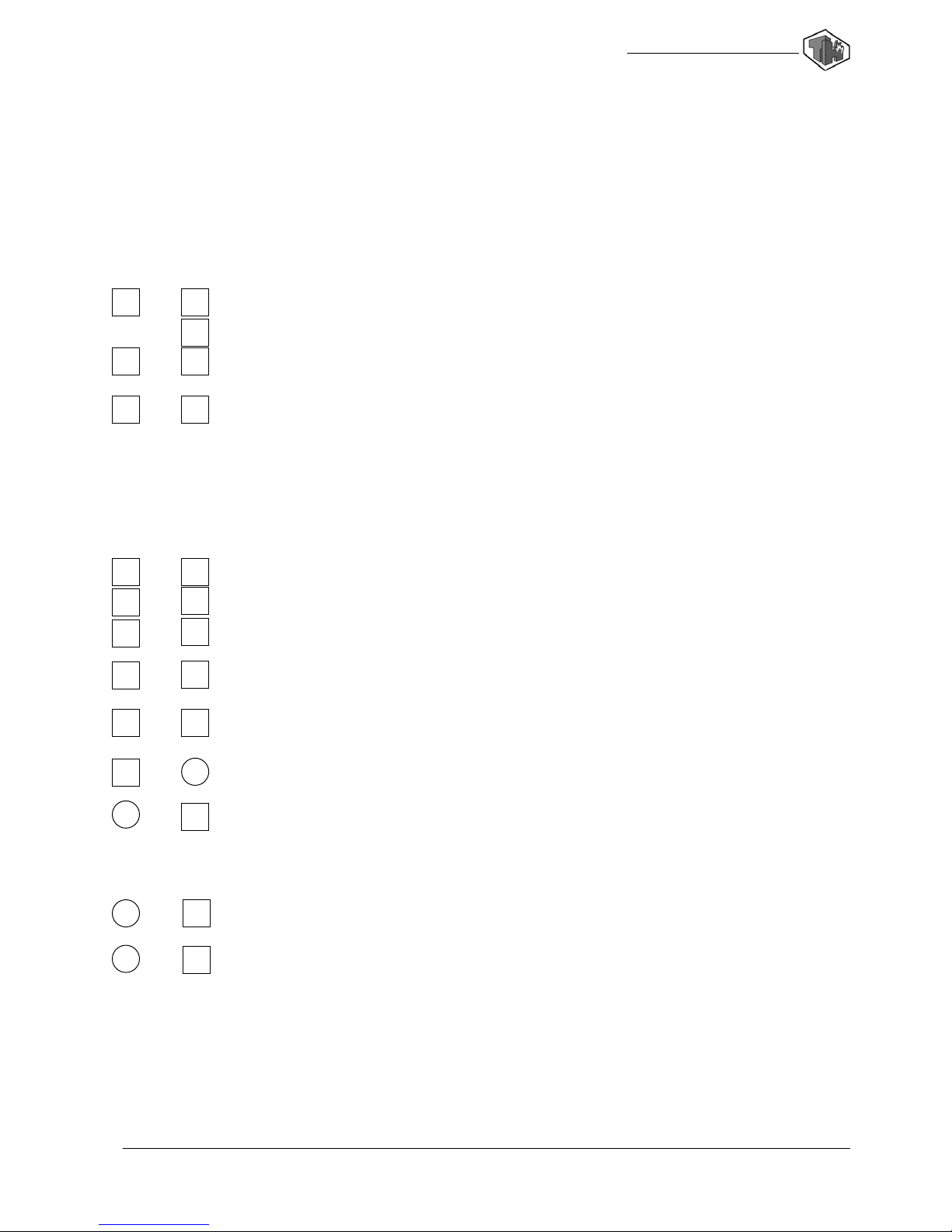
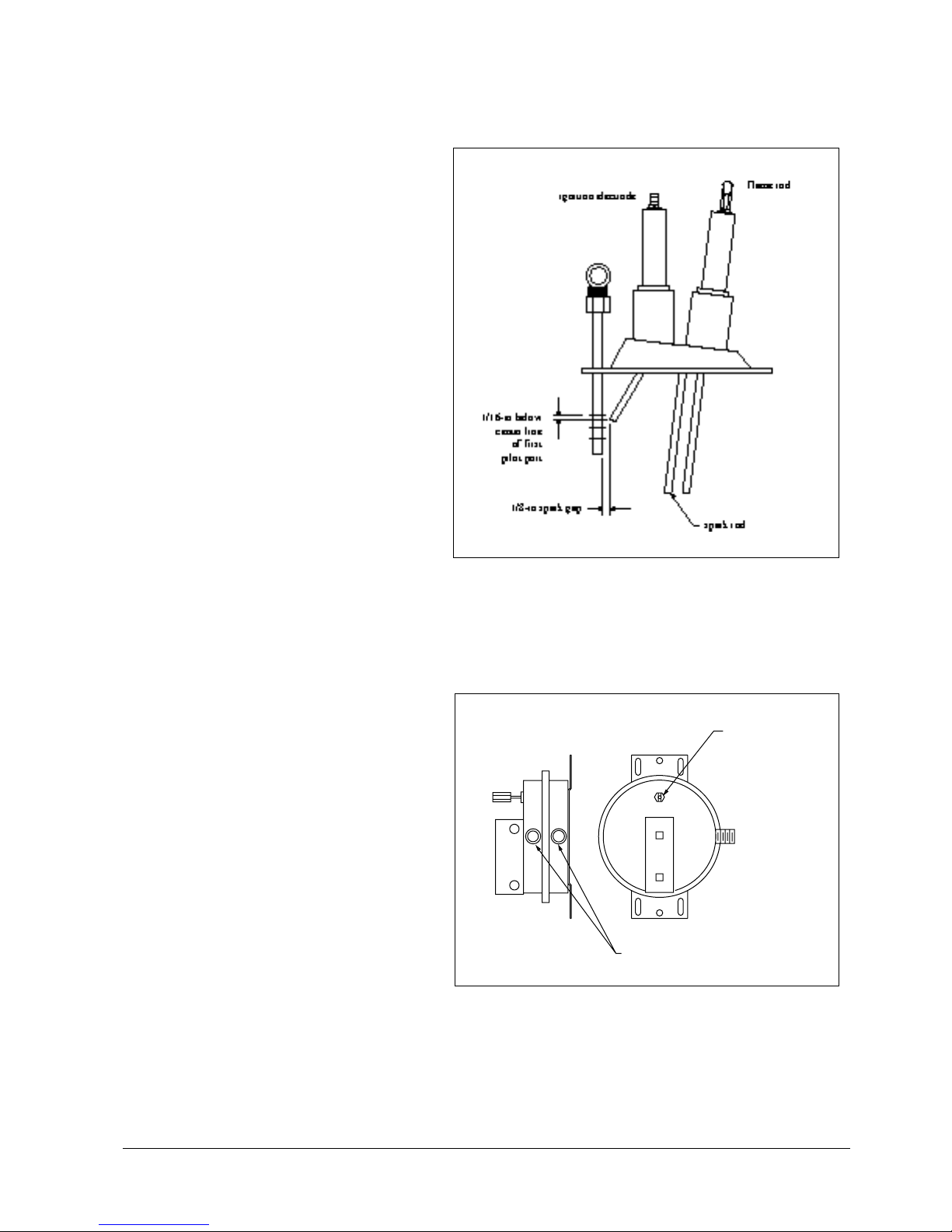
Control Adjustments
Ignition
1. Clean and dry electrodes.
2. Check porcelain insulators for cracks or
moisture. Replace if necessary.
3. Adjust as shown.
4. Secure ignition leads.
5. Replace spark electrode if defective.
Air-Flow Control
Setting control
1. Turn ON/OFF switch to ON.
2. With unit operating at high-fire, turn
adjusting screw clockwise until burner
goes OFF.
3. Turn adjusting screw counter-clockwise
1/2 turn at a time until burner re-ignites.
To check setting
1. Set remote thermostat on highest setting.
2. Observe that when operating on high-fire,
the switch does not break contact.
Ignition Assembly
Airflow Control
adjusting screw
airflow tube connections

19
TEMP-HEAT
®

One Rupp Plaza
3700 West Preserve Boulevard
Burnsville, Minnesota 55337-7746
1-800-836-7432
Boston, MA 800-666-8133 fax 508-624-0036
Chicago, IL 800-283-2843 fax 847-931-7704
Cleveland, OH 800-443-3301 fax 330-721-7742
Columbus, OH 800-444-3481 fax 614-471-1933
Denver, CO 800-577-7053 fax 303-783-8579
Detroit, MI 800-678-1488 fax 248-526-9527
Duluth, MN 888-539-5438 fax 218-722-6701
Minneapolis, MN 800-836-7432 fax 612-707-5104
Newark, DE 800-232-7419 fax 302-369-8022
Watertown, WI 800-558-9209 fax 920-261-4523
RUPP Industries manufactures, sells and rents commercial, industrial
and construction equipment. Our employees — our most valuable
asset, are dedicated to finding innovative solutions that fulfill our
customers’ product and service requirements.
0123.9901 © RUPP Industries, Inc. 1999 Printed in USA
Table of contents


