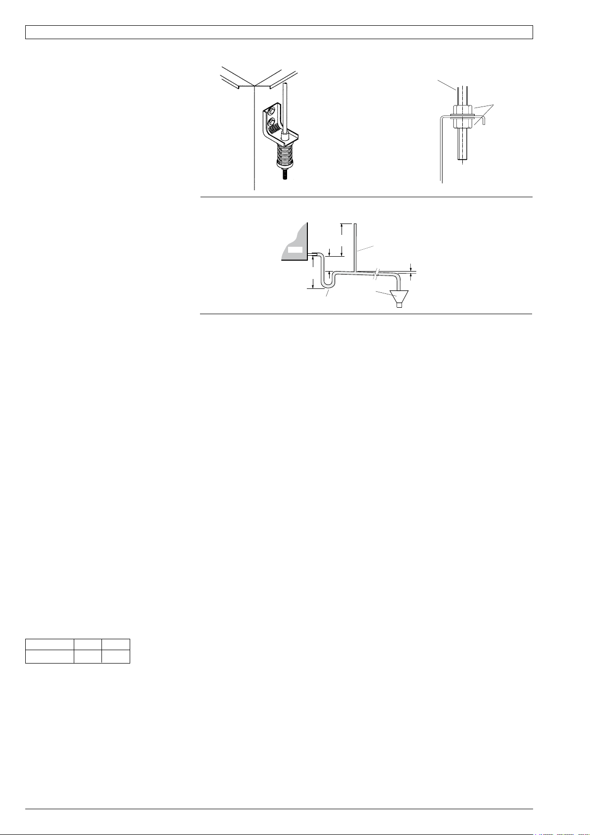
If a more rigid installation can be tolerated,
then suspend the unit from four threaded
rods using locknuts (not supplied), as shown
in Fig. 4.
Mount top of the unit level as it comes with a
sloping drain tray. This tray is not reversible,
i.e. the drain exit can only be at the opposite
end to the compressor.
The unit must be mounted with sufcient
height for the condensate drain to be
'U' trapped outside the unit (see gure 5).
Alternatively t a condensate lift-pump.
The drain line must not be piped to a level
above the drain tray.
When nally positioned, tighten the lock
nuts on the mounting rods to give a rm
installation (see Fig. 3).
The drain line must be maintained at least
19 mm ID along its full length. A vent pipe is
recommended for drain pipes longer than
4 m (refer gure 4). Check drain by pouring
water into the drain tray and ensuring
that it clears. Failure to adhere to these
instructions could cause ooding.
The HWP unit's IN and OUT water
connections are male pipe threaded (refer
Fig. 1). The two 600 mm
exible high pressure water hoses supplied
have female pipe threaded connections at
each end. Maximum water pressure for
each hose is 1720 kPa (250 psi). The HWP
unit alone, excluding hoses, will withstand
4480 kPa (650 psi).
Poor quality water supply must be pre-
ltered and it is essential that adequate
water treatment is maintained, particularly
where open cooling towers are used.
: It is required that the water supply
system be tted with a water ow switch and
water pump safety interlock. These items
prevent the HWP units from going into fail
safe lockout status due to a loss of water
ow. Failure to install the above items would
require the resetting of all HWP units in the
system - either by breaking the power supply
to each unit or breaking the thermostat
control circuit.
HWPSR units require a minimum water
supply temperature of 17°C.
It is recommended that a circuit balancing
valve be tted to maintain water ow at a
constant rate. The minimum water ow rates
in litres per second (l/s) are as follows:
:
Minimium 0.45 0.67
The air conditioner should be connected
to the appropriate power supply for each
model, as specied in the wiring diagram,
with neutral and adequate earth. The supply
to have an accessible switch to allow
isolation of the unit. Wire the heating and
cooling room thermostat to the electrical
terminals adhering to the wiring diagram
supplied with the unit. All wiring to the air
conditioner must comply with the wiring
regulations of the local electrical authority.
The Indoor fan can be switched ON through
the thermostat by selecting High, Medium
or Low fan speed, or via BMS. This can be
done without starting the compressor.
The factory default setting of the maximum
fan speed and the fan speed range (High –
Low) are specied on the wiring diagram.
If either High speed or Low speed need
adjusting, proceed as follows for:
Units supplied with SAT-2 Controller
Use DIP Switches 1 to 5 on the Analogue
Level Controller (ALC) board located in the
electrical box – refer wiring diagram. DIP
switches 1 to 3 determine the maximum fan
speed. DIP switches 3 & 4 determine the fan
speed range, below the maximum setting.
Units supplied with UC7 Controller
Use the UC7 Controller board to adjust the
indoor fan speed:
i. Set DIP switch 5 on the UC7 to ON, then
reset the controller by cycling mains
power to the unit off and on again.
ii. Ensure the compressor is off and the
thermostat or BMS does not request for
the compressor to start.
iii. Press and hold down the SW3 push
button on the UC7 circuit board until the
display shows the letter 'H', then release
the push button.
iv. The indoor fan will start and run at the
'High' speed setting (factory default
setting is 7.5V). The display will show the
value ('7.5') and the indoor fan will run at
the selected speed.
v. Each following press on the SW3
push button increases the indoor fan
control voltage in steps of 0.5V, up to a
maximum of 10.0V. Pressing the push
button again when value 10.0 is shown
returns the fan control voltage down to
the minimum value for 'High' fan speed
(3.0V).
vi. When the desired setting for high fan
speed is selected then wait for 30
seconds. The controller will save the
selected value in its memory and return
to normal operation.
vii. To adjust the indoor fan 'Low' speed
repeat the above procedure but wait until
the display shows the letter 'L' before
releasing the push button. The factory
default value for low speed is 5.5V.
HWP-CKSYD & HWP-RKSYD models:
Once set, your fan speed range can
then be set to: LOW, MED and HIGH
(DIP1 switch 1 'OFF') across the selected
range.
Refer to HWP 77/96 Data Sheet pamphlets
for detailed information on air handling
performance and water ow rates.
Unit protection is incorporated in either:
a.) UC7 Controller, or
b.) SAT-2 Controller,
depending on which HWP model is being
installed.
A pump verication relay ensures that water
is owing before the compressor will start.
A high pressure lockout protects the unit
from low water ow in cooling mode, or fan
failure in heating mode. Sensors protect
against low air coil temperature and loss of
refrigerant. Units include an anti rapid cycle
device for compressor protection.
HWPSR units also have a low refrigerant
temp. safety thermostat to protect against
icing up of the water within the unit's tube-in-
tube heat exchanger.
A non-specic fault LED/ output signal is
also included for remote fault indication to
building management systems (refer wiring).
For models supplied with UC7 Controller,
refer to the label on the unit for operation &
fault diagnosic information.
: Lockout protection can be reset by
switching unit's power supply off and on.
Lockout protection will also reset when the
thermostat switches, or is switched to the
dead zone.
MOUNTING
ROD TIGHTEN
LOCKNUTS
FOR
STRENGTH
PREFERRED
MOUNTING
SYSTEM
(SUPPLIED)
OPEN
DRAIN
MINIMUM
SLOPE
20 mm PER m
(1 IN 50)
50 mm
MINIMUM
100 mm
APPROX.
'U' TRAP
100 mm
APPROX.
VENT PIPE
FOR LONG
CONDENSATE
DRAIN RUNS
UNIT


