- 2 -
REFRIGERATION SYSTEMWIRING
3. REFRIGERATION SYSTEM
3.1 General
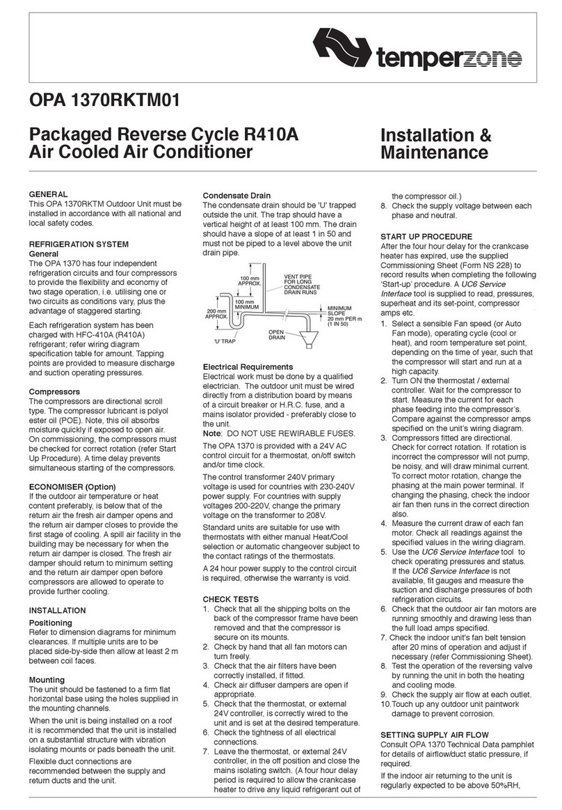
The OPA 700/800 models have two independent
refrigeration circuits and two compressors to provide
the exibility and economy of two stage operation, i.e.
utilising one or two circuits as conditions vary, plus the
advantage of staggered starting.
Units are supplied with a UC6 service interface display
tted for ease of service, maintenance and trouble
shooting. Operating pressures and status can be read
from its various display screens (refer user manual).
Each refrigeration system has been charged with
HFC-410A (R410A) refrigerant; refer wiring diagram
specication table for amount. This charge is based
on nominal capacity, nominal conditions and nominal
airow and is sufcient under these conditions to
maintain a refrigerant superheat of approximately 6
Kelvin. If the unit is installed in subtropical or tropical
conditions, has a high fresh air content or has been
installed with maximum supply
air quantity, the superheat should be checked and if
found to be above 6 Kelvin, refrigerant may need to
be added to the system to return the superheat to the
factory required state. These readings should be taken
with each stage operating independently and after the
space has achieved conditions. The additional charge
should be recorded for future reference.
3.2 Compressors
The compressors are directional scroll type. The
compressor lubricant is polyolester oil (POE). Note, this
oil absorbs moisture quickly if exposed to open air.
On commissioning, the compressors must be checked
for correct rotation (refer Start Up Procedure). A
time delay prevents simultaneous starting of the
compressors.
3.3 Economiser (Option)
If the outdoor air temperature or heat (enthalpy) content
preferably, is below that of the return air the fresh air
damper opens and the return air damper closes to
provide the rst stage of cooling. The fresh air damper
should return to minimum setting and the return air
damper open before the compressors are allowed to
operate to provide further cooling.
3.4 Setting Supply Air Flow
If the indoor air returning to the unit is regularly
expected to be above 50%RH, then the coil face
velocity should be limited to be 2.5 m/s or less (refer Air
Handling graph on page 5).
High humidity levels can occur in tropical or subtropical
conditions, and/or when heavily moisture laden fresh
air is introduced. Select a fan speed that avoids water
carry-over problems.
In a free blow or low resistance application, beware
of exceeding the fan motor’s full load amp limit (refer
wiring diagram).
The indoor air fan motor is tted with a factory set
adjustable pitch pulley. Instructions for the adjustment
of pulleys is included on the back page of the supplied
Commissioning Sheet. One revolution of adjustment is
equal to approx. 7% change in air volume ow rate.
4. WIRING
4.1 Electrical Requirements
Electrical work must be done by a qualied electrician.
DANGER LIVE ELECTRICAL CONNECTIONS. ONLY QUALIFIED
PERSONS WHO ARE COMPETENTLY TRAINED SHOULD
PERFORM SERVICE AND MAINTENANCE TASKS.
The unit must be wired directly from a distribution board
by means of a circuit breaker or H.R.C. fuse, and a
mains isolator provided - preferably close to the unit.
Note: DO NOT USE REWIRABLE FUSES.
The OPA unit is provided with a 24V ac control circuit
thermostat (TZT Optional), on/off switch and/or time
clock, eld supplied and tted. The control transformer
240V primary is used for countries with 230-240V
power supply. Alternatively control can be via a Modbus
connection.
For countries with supply voltages 200-220V, change
the primary voltage on the transformer to 208V.
Standard units are suitable for use with thermostats
with either manual Heat/Cool selection or automatic
changeover subject to the contact ratings of the
thermostats.
A 24 hour power supply to the compressor crank case
heaters is required, otherwise the warranty is void.
4.2 Unit Controller (UC6)
The temperzone Unit Controller 6 (UC6) combines the
µPC controller board from Carel plus an interface board
to connect temperzone standard sensors and plugs.
The UC6 receives requests such as “Unit On/Off”,
“Start 1 or 2 compressors”, “Activate HEAT (Reverse
Cycle)” and transfers these requests to the outputs after
enforcing safety timers. The UC6 ensures unit safety by
continuously monitoring input signals such as pressures
and temperatures. Beside the normal controls and unit
safety the UC6 has many other functions, for example
head pressure control, capacity control, superheat
control, serial communications and more.
The Unit Controller provides system protection
functions such as coil frost protection, de-icing, high
head pressure and low suction pressure cut-out. It also
protects against rapid cycling of the compressor(s) and
loss of refrigerant. The UC6 regulates the superheat
of the refrigeration system by controlling the position
of an electronic expansion valve (EEV). Various
methods of head pressure control (or limiting) are
employed in temperzone units. The particular method
used varies from model to model, but is also handled
by the Unit Controller. In combination, these features
deliver optimised performance across a wide operating
temperature range.
As a result of the UC6’s control of these inter-related
functions, the outdoor fans may take some time to start
rotating after each compressor start. They may also run
on when the compressor stops. The fans will stop during
a de-ice cycle and the speed will vary either smoothly,
or in steps, in order to protect against excessively low or
high head pressure.
Refer to temperzone for operation & fault diagnostics
information OR www.temperzone.biz.
