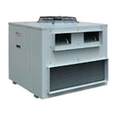
4. GME electrical box–to–OSA outdoor
unit interconnecting lead;
12.5 m or 25 m; 7 core.
5. Additional HAN-L6 Wall Control plaques
(Note: maximium of 4 plaques in total).
Installation
The HAN-L6 Controller board is supplied
pre-installed inside the GME unit's
electrical box.
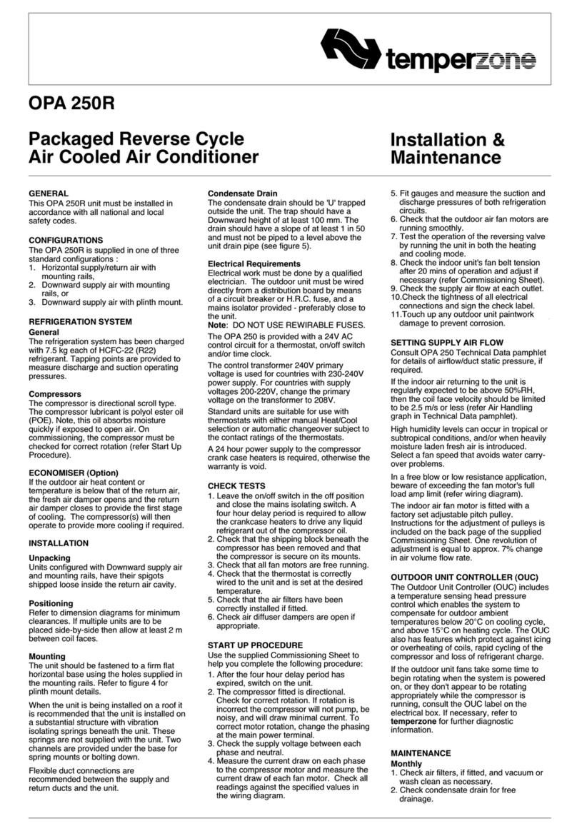
1. Isolate the GME unit from power supply,
then remove electrical box cover.
2. Connect one end of the interconnecting
cable (supplied separately) to the unit's
terminals and the other end to your OSA
outdoor unit as per wiring diagram,
page 4.
4. Remove the Wall Control's interface
lead from its box and connect one end
of the interface lead to the colour coded
terminal block on the HAN-L6 Controller
board. Trace the remaining length of the
lead to the wall plaque's intended
location.
5. Ensure all interface and sensor wires
are run separately and away from main
power supply wires, including the
interconnecting cable.
6. Replace the electrical box cover.
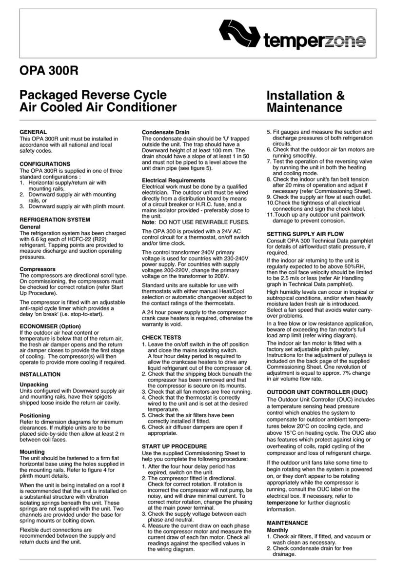
HAN-L6 Wall Control
Refer to the separate Installation
Instructions supplied with the HAN-L6 Wall
Control.
Remote Air Temperature Sensor/s
(option)
The air temperature sensor is by default
located in the Wall plaque. Optional remote
air temperature sensors are available so
that the measurement of the room
temperature can be taken away from the
wall plaque, eg. elsewhere in the room or in
the return air duct.
If plugging the remote sensor into the Wall
Control (TH1R) a jumper (JP1) must be
repositioned to switch the active sensor to
the remote location (refer separate HAN-L6
Installation Instructions).
Remote sensors can be plugged directly
into the Controller board (PCB). This board
accepts up to four sensors which are
designated as 'zones' two to five. The first
zone will always be the Wall Control itself.
The Controller will always use the average
of the zones selected. Refer to the
separate installation instructions supplied
with the PCB for further details.
COMMISSIONING
Indoor Unit
1. Check that the thermostat is correctly
wired and set at the desired
temperature.
2. Check that the air filter is clean.
3. Check that the fan runs freely without
vibration.
4. Check condensate drain for free
drainage.
5. Refer to Outdoor Unit
Installation &
Maintenance
instructions and
Wall Thermostat
User's Operating
Instructions
to complete the start-up
and commissioning procedure for the
complete air conditioning system.
6. Run the motorised louvre to check
up/down air distribution. Use the switch
to set up/down louvre in fixed position,
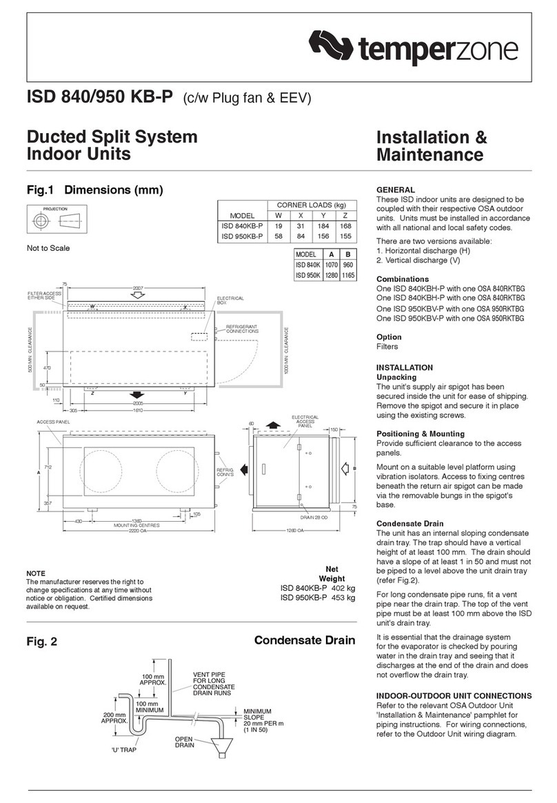
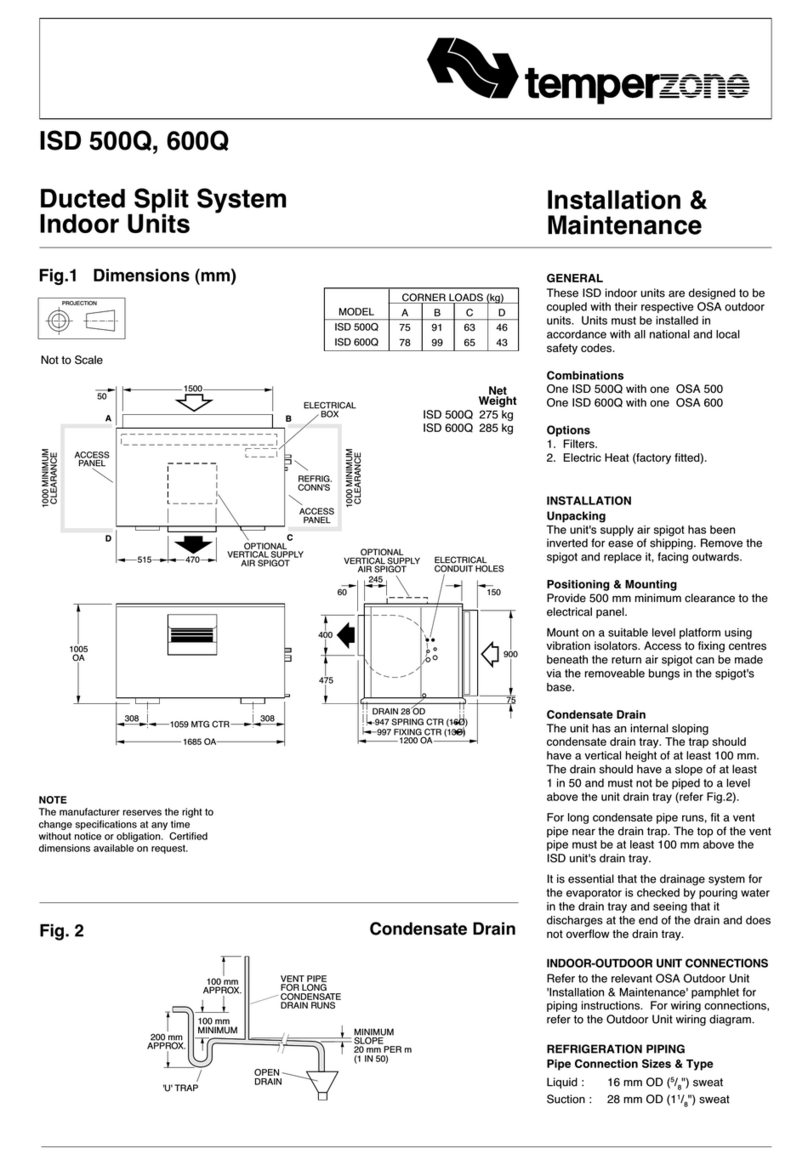
2. Install four M8 threaded hanging rods
(not supplied) to protrude no more than
30 mm below the level of the mounting
bracket flange (refer figure 3).
3. Thread on and tighten the lower washer
and locknut sets (not supplied) to secure
the left and right mounting brackets.
Note: Mounting bracket flanges face
inwards.
4. Adjust distance between mounting
brackets to match dimensions in figure 3.
5. Lift the unit to the mounting brackets
locating the two protruding bolts, at each
end of the unit, securely into the two
slots provided in each mounting bracket,
then tighten bolts to secure the GME unit.
6. Check that the secured GME is installed
level to facilitate condensate drainage.
7. Complete all refrigeration piping
connections (refer 'Indoor-Outdoor Unit
Connections').
8. Fit the insulated condensate drain
extension, orientated so that the drain
vent tube is at the highest point in the
condensate line.
9. After completing all piping connections
replace the GME unit's left and right
endcaps as follows:
a. Place each endcap slightly forward of
the appropriate end of the unit,
b. Compress the endcap at its centre
and slide back hooking the endcaps
hook under the 'U' shaped bracket on
the unit and into position .
c. Secure each with the screws removed
earlier from behind the filter panels.
Wall / Floor Installation
Vertically mounted, the refrigeration and
wiring connections can be made through
the back or base of the unit.
1. Measure and cut wall recess, if required.
2. Secure the mounting brackets to the wall
using fastenings suitable for the wall
construction and weight of the GME unit.
(Note: Mounting bracket flanges to face
inwards.)
3. Refer to 'Underceiling Installation'
instructions, steps 4 to 9 above, to
complete vertically mounted installation.
INDOOR-OUTDOOR UNIT
CONNECTIONS
Refer to the relevant OSA Outdoor Unit
'Installation & Maintenance' pamphlet for
piping instructions. For wiring connections,
refer to the Outdoor Unit wiring diagram in
conjunction with the GME wiring diagram
on this pamphlet.
REFRIGERATION PIPING
The GME Underceiling is shipped from the
factory with a holding charge of dry
nitrogen. Refer to the Outdoor Unit
'Installation & Maintenance' pamphlet for
evacuation procedure.
GME 152 refrigerant line connections are:
Liquid: 6 mm OD (1/4") flare nut
Gas: 13 mm OD (1/2") flare nut
GME 222 refrigerant line connections are:
Liquid: 10 mm OD (3/8") flare nut
Gas: 16 mm OD (5/8") flare nut
GME 302 refrigerant line connections are:
Liquid: 10 mm OD (3/8") flare nut
Gas: 19 mm OD (3/4") sweat
GME 402 refrigerant line connections are:
Liquid: 13 mm OD (1/2") flare nut
Gas: 19 mm OD (3/4") sweat
GME 502, 702 refrig. line connections are:
Liquid: 13 mm OD (1/2") flare nut
Gas: 22 mm OD (7/8") sweat
Separation Limits
Maximum Pipe Length: Up to 30 m total *1
Indoor Unit above Outdoor Unit : 12 m *2
Outdoor Unit above Indoor Unit : 18 m *2
*125 m total for GME 152 when
connected to OSA 45.
*210 m for GME 152 when
connected to OSA 45.
For line lengths in excess of the above,
contact the manufacturer's nearest sales
office for additional piping requirements.
CONDENSATE DRAIN
Connect a 19 mm ID drain pipe (not
supplied) to the GME's drain connection.
Maintain a downwards slope of at least
1 in 50 (20 mm/m) along the drain line. No
‘U’ trap is necessary.
Insulation of the GME 502 and 702 drain
pipes is recommended especially in high
humidity environments.
Note: The unit has a right angled drain
tray to allow for wall or ceiling installation.
ELECTRICAL WIRING
The electrical supply required (via the
Outdoor Unit) is specified on the Outdoor
Unit's wiring diagram.
Electrical work must be carried out by a
qualified electrician in accordance with
local supply authority regulations and the
wiring diagram.
Note: The TTS-11 Wall Thermostat
automatically switches the indoor fan off
during de-ice, therefore no additional wiring
is required to achieve this result.
Note: The HAN-L6 Controller automatically
switches the indoor fan off during de-ice,
therefore no additional wiring is required to
achieve this result.
COOLING OPERATION
An Outdoor Unit fan speed controller is
recommended where indoor cooling is
required at ambient conditions below
20°C.
HAN-L6 CONTROLLER
The following components are supplied in a
box beside the GME electrical box:
1. HAN-L6 Wall Control plaque, including
wall mounting plate and screws.
2. 10 m interface lead (plaque-to-electrical
box).
3.
User's Operating Instructions
booklet.
4. HAN-L6 Installation Instructions.
Optional
1. Remote return air temperature sensor
on lead; 5 m or 10 m.
2. Remote wall mounted air temp. sensor
on lead; 5 m or 10 m.
3. 20 m extended interface lead
(plaque-to-electrical box).
