Tempest 400 User manual
What’s in the box
BaseStation
•
TM-400 series Base
•
Power Cord
•
2dBi Omni-directional whip antenna (x2)
•
3.5mm to 3.5mm 3 conductor data pairing cable
----- Used to pair a Base to the Belt(s)
•
USB A to B cable ----- Used to upgrade Base firmware
•
USB A to Mini B ----- Used to upgrade Belt firmware
•
Base-Sync cable
----- Used if you have more than one Base
----- Improves RF performance when using multiple systems
•
CD with manual, T-Desk software
BeltStation
•
TM-400 series Belt
•
Li-Poly rechargeable battery
•
5VDC wall charger with Mini USB connector
Remote Transceiver (optional)
•
Remote RF transceiver
•
RJ-45 to RJ-45 CAT-5 cable
•
2dBi Omni-directional whip antenna (x2)
•
Mounting Plate and screws
What else you may need
•
Headset, one for each user
----- May be dynamic or electret microphone, with a
4-PIN XLR female connector
•
3-PIN XLR cables to connect to external 2-Wire
Intercom system
•
RJ-45 cables to connect to external 4-Wire Intercom system
•
RJ-45 cable to connect to PC for T-Desk LAN control
Directional Antenna Kit (optional)
•
Directional antennas (x2)
•
Mounting brackets (x2)
•
Antenna Mounting Bar
•
“C” Clamp Mount
•
“RP-TNC” to “N” cables (x2)
5 Bay Battery Charger (optional)
•
Battery Charger
•
AC Cable
Note: Charge ALL BeltStation batteries prior to set-up
Tempest ®400 Quick Start Guide

Select a location for the
BaseStation and/or Remote
Transceiver
1
2
3
System range and performance may be greatly reduced if antennas are
blocked or obstructed.
•
Always operate the system with both antennas attached, locate as high as
possible and away from all obstructions (especially metal).
•
Never use antennas on the back of the Base when the Base is in a rack
•
When using the Whip (omni-directional) antennas, always locate
antennas as close as possible to the center of the area you want to cover.
•
When using directional antennas, always aim both directional antennas in
the same general direction.
•
When remotely locating antennas, use only high quality 50 ohm,
low loss, RF cable (30 ft max).
•
Remote antenna location of up to 1500 ft using standard CAT-5 wiring may
be achieved using the optional Tempest Remote Transceiver.
----- This must be a point to point connection
•
Connect the AC power cord to the Base and to the AC wall outlet
•
Turn the Base on via the front panel ON/OFF switch
•
The first time you power up the Base, you will be prompted to “select an
authorized band for your location”.
•
There are seven RF bands that use different parts of the 2.4GHz spectrum.
Please note:
* Band 1 is appropriate for most, but not all, locations worldwide (US is band 1)
* Some countries require that you use a limited portion of the 2.4GHz band
* It is the user’s responsibility to ensure that you select a band that is permitted
for use in your location
------ Scroll to an appropriate band for your location and press Enter to select.
------ Press MENU to return to the operational screen
Power ON the BaseStation
Selecting the RF band
ON/OFF
MHz
Band Start End Wide Avoid 802.11b/g
1 2400 2480 80 None
2 2400 2450 50 11
3 2423 2473 50 1
4 2431 2480 49 1,2
5 2400 2428 28 7,8,9,10,11
6 2423 2450 27 1,11
7 2453 2480 27 1,2,3,4,5,6,7
4
1. From the front of the Base, follow the steps below :
2. Press MENU (Main Menu)
3. Press 1 (BaseStation Settings) and scroll down to 7. Press ENTER
4. You will receive a Tech Menu Warning. Press ENTER to proceed.
5. Press ENTER 1 (Radio Configuration).
6. Press 1 (Network Number) and select a network other than zero & press
ENTER to save.
7. Press MENU
-------- If you have multiple Bases, ensure that you select a different Network
Number for each Base.
-------- Collocated Bases should have different network numbers separated
by at least four (e.g. 1, 5, 9, 13… or 2, 6, 10, 14…)
8. Press 2 (Lockout Key) and select a lockout key other than 255 & press
ENTER to save.
9. Press MENU repeatedly until you get back to the Operational screen.
Power the Base OFF
10. Wait 10 seconds and power the Base ON again
Changing the Default RF
Configuration
Tempest
®
BaseStations and BeltStations are shipped with a
default RF configuration. It is highly recommended that you
change your system from the default to ensure proper RF perfor-
mance especially in the presence of other Tempest systems.
A BeltStation must be paired with a BaseStation for any com-
munication to take place. Pairing should be done AFTER the
default RF configuration is changed on the BaseStation.
P
P
P
P
Important things you need to know
All BeltStations must be paired with each BaseStation with
which it will be operated.
Charge the BeltStation batteries prior to starting set-up.
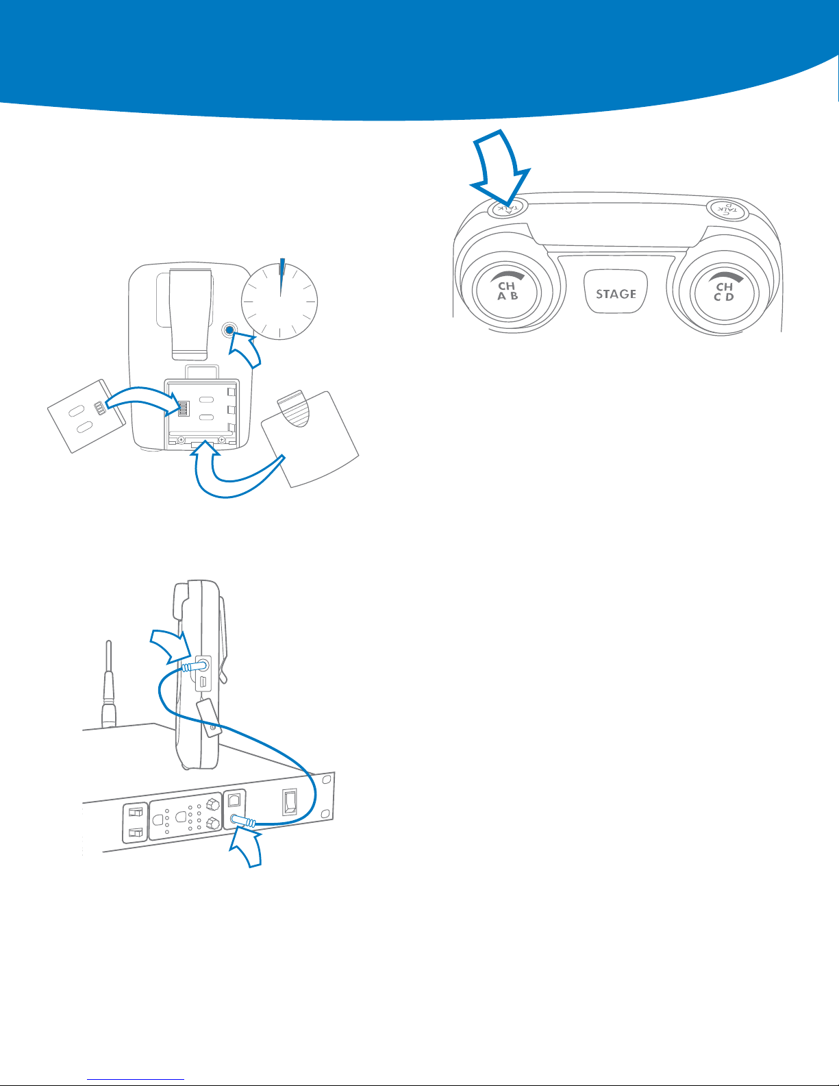
6
7
8
9
•
Remove the battery door by pressing down and back
•
Install the battery (or 3 AA batteries) & replace the battery door
•
Press and hold the ON/OFF button for two seconds
•
The BeltStation will vibrate as it powers up
•
Power the Belt OFF by pressing and holding the ON/OFF button
for two seconds
•
Plug a headset into each Belt
• To set mic gain, Press ENTER. Scroll down to set controls
• Select mic gain and Press ENTER to save
•
Set the mic gain for the headset that you are using
------ Speak loudly into the microphone and adjust the mic gain setting so that
the blue talk LED just starts to flash red. Press ENTER to save
•
Select the desired communication channel by pressing the A/B or C/D
channel selector
•
Set the headset listen volume by turning the A/B or C/D rotary control
•
Press the TALK button to talk to others on the selected channel (the blue
flashing LED will light continuously when talk is enabled on that channel)*
•
Confirm the desired talk channel and talk status by observing the Belt
LCD screen
•
Select the correct intercom type on the front of the Base
------ Intercom type select switch A&B controls both intercom channels
A and B. C&D controls both intercom channels C and D
------ CLEAR-COM is used for Clear-Com and Clear-Com compatible
2-Wire systems
------ RTS is used for RTS and RTS compatible systems
--- BAL is used for Telex AudioCom & AudioCom compatible systems
•
Connect 3-PIN XLR cables to the back of the Base for the appropriate channel
•
Press the first SEL button to select an intercom channel A through D
•
Press the second SEL button to select 2-Wire
•
Use the IN and OUT rotary controls to set the in (from 2-Wire to Base)
and out (from Base to 2-Wire) levels
•
Perform Auto-Null from the BaseStation* (See Manual for Details)
•
The intercom type select switches do not apply to 4-Wire operation*
•
Connect RJ-45 cables to the back of the Base for the appropriate channel
•
Press the first SEL button to select an intercom channel A through D
•
Press the second SEL button to select 4-Wire
•
Use the IN and OUT rotary controls to set the in (from 4-Wire to Base)
and out (from Base to 4-Wire) levels.
*Refer to the Tempest Owner’s Manual for detailed system information.
Power ON the BeltStation
Pair BeltStations to the
BaseStations
Start Communicating
Connecting to External
2-wire Intercom Systems
Connecting to External
4-wire Intercom systems
2 sec
POWER ON
5
•
Confirm the Base is powered ON
•
Confirm the Belt is powered OFF
•
Connect the 3.5mm data pairing cable from the Base to the Belt
•
Power ON the Belt while watching the Belt LCD screen
•
The Belt will vibrate and “Pairing Complete” will appear momentarily on the
Belt LCD
•
The belt will return to the operational screen and Log into the Base
•
The belt will appear in the first available slot on the Base LCD screen
•
Repeat for each Belt
Note: BeltStations are named to their default setting name. They may be renamed.
Quick Start Guide
Phone 334.321.2307
Fax 334.821.6861
www.tempestwireless.com
Tempest®
205 Technology Parkway
Auburn, Alabama 36830
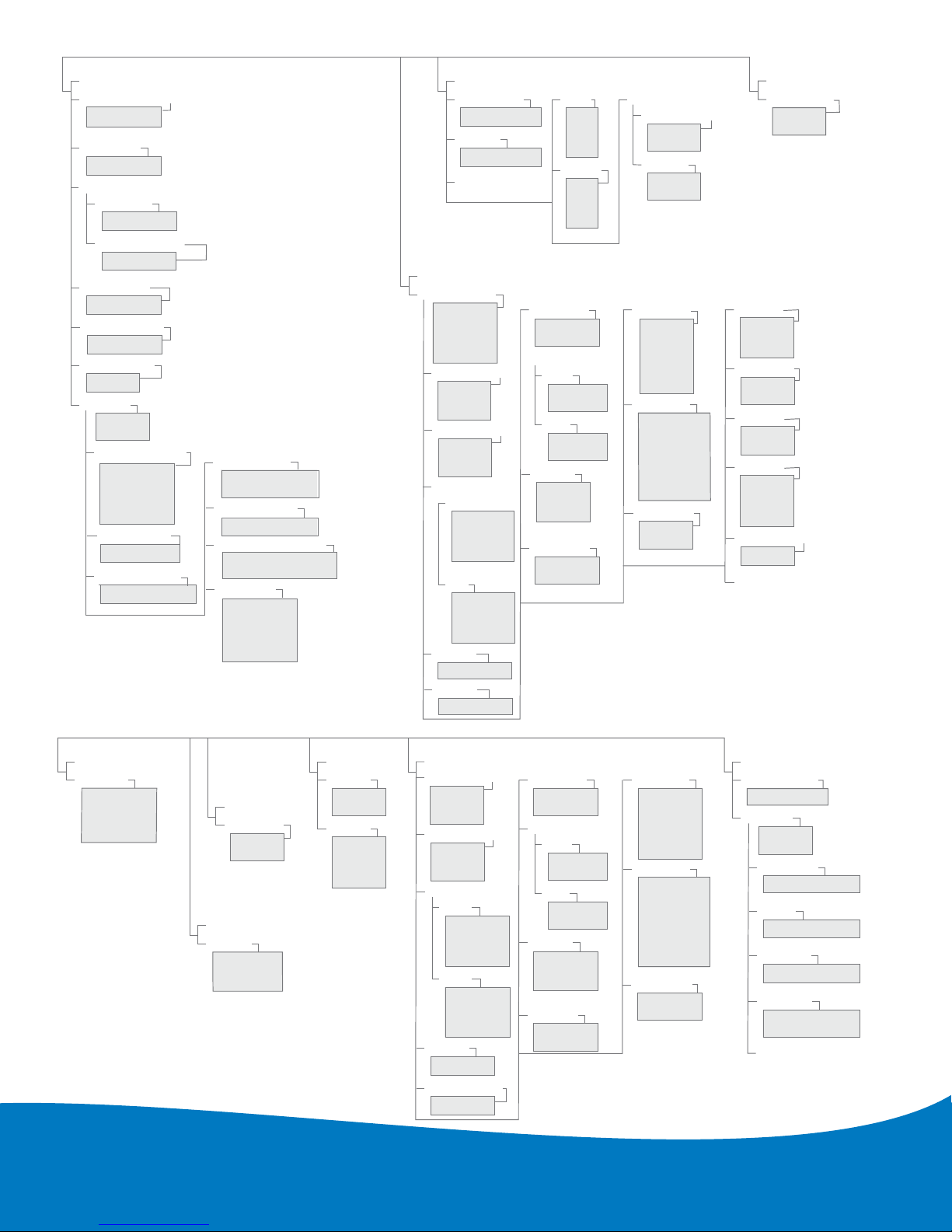
ion Menu
BaseStation Menu
WIRED INTERCOM SETTINGS
Intercom Levels
Set Intercom Levels
Manual Null
Auto-Null
Auto-Null Now
Aux In
A
B
C
D
Aux Out
A
B
C
D
Stage Announce
S/A Relay
Enable
Disable
Audio Output/Level
Scroll To
Adjust
MULTI-BASE
Set As Master
On
Off
BASESTATION SETTINGS
Sidetone
(Scroll)
Headset Vol/Sidetone
(Scroll To Adjust)
Set Mic Gain
(Scroll To Adjust)
LED Brightness
Base Name
Name BaseStation
Lock
Front Panel Lack
Proceed
Exit
Tech Menu
e
sss
es
TCP/IP Addr
Subnet Mask
Default Gateway
MA
TCP/ IP Mode
C Addr
LAN Settings
Set Network
Number
Set Lockout Key
Set Band
Radio Confi
guration
Security
Settings
Disabled
Diagnostics Mode
System Information
Factory Defaults
Restore Factory Defaults
Clear Memory
LCD Adjustments
(Scroll To Adjust)
Backlight Brightness
(Scroll To Adjust)
Set Contrast
BELTSTATION SETTINGS
Select BeltStation
BeltStation 1
BeltStation 2
BeltStation 3
BeltStation 4
BeltStation 5
Talk Button A/B
Latch
Latch
Momentary
Disable
Talk Button C/D
Momentary
Disable
Mic Gain
(Scroll To Adjust)
Side Tone
(Scroll To Adjust)
Stage Announce
Audio
Momentary
Disable
Relay
Enable
Disable
Volume Limit
Min Vol
Max Vol
Call Function
Enable
Disable
Call Alert
Wireless ISO
Enable
Disable
Select Relay
Relay 1
Relay 2
Relay 3
Relay 4
Re
None
lay 5
Relay Button
Talk A/B
Talk C/D
Ch A/B
Ch C/D
Stage
Enter
Low Battery 10%
Name
Base Slot Assignment
BeltStation
Belt Name
Battery Alert
On
Off
Lock Keys
A or B
A Only
B Only
Channel Select
A/B
C/D
C or D
C Only
D Only
BeltStat
Current Base
BaseStation 1
BaseStation 2
BaseStation 3…
SELECT BASE
Select Base
BATTERY
Battery Alert
Enable
Disable
LCD/LED
LCD Light
Enable
Disable
Talk LEDs
High
Med
Low
Off
LOCK KEYS
Lock Keys
Lock Buttons
Volume
Talk
Set Defaults
Restore Factory Defaults
Clear Memory
BELT SETTINGS
Belt Name
Te
Name Beltstation
ch Menu
Proceed
Exit
Radio Config
Radio Information
Diagnostics
System Information
Base Slot
Security
Disabled
SET CONTROLS
Mic Gain
(Scroll To Set)
Sidetone Volume
(Scroll To Set)
Select Relay
Relay 1
Relay 2
Relay 3
Relay 4
Relay 5
Wireless ISO
Enable
Disable
Call Alert
Audible
Vibrate
Both
Call Button
Enable
Disable
Stage Announce
Audio
Momentary
Disable
Relay
Enable
Disable
Relay Button
Talk A/B
Talk C/D
Ch A/B
Ch C/D
Stage
Enter
Low Battery 10%
Volume Limit
Min Vol
Max Vol
A or B
A Only
B Only
Channel Select
A/B
C/D
C or D
C Only
D Only
Echo Cancellation
On/Off
Display Slot Assignments
Static
Dynamic
Radio Information
Neither A or B
Neither C or D
Neither A or B
Neither C or D
None
Enable
Disable
Lock Buttons
Volume
Talk
LCD Light
Talk LEDs
High
Meduim
Low
Off
Audible
Vibrate
Both
Talk Button A/B
Latch
Latch
Momentary
Disable
Talk Button C/D
Momentary
Disable
© 2009 CoachComm LLC. All rights reserved.
Tempest®is a registered trademark of CoachComm, LLC.
Tempest is manufactured by CoachComm, LLC and is distributed by Clear-Com Communication Systems.
®Clear-Com and the Clear-Com Communication Systems logo are registered trademarks of The Vitec Group plc
© Telex, AudioCom and RTS are registered trademarks of Telex Communications, Inc.
Table of contents


