Tempest POWER BLOWER User manual

POWER BLOWER
OPERATIONS MANUAL
APRIL 2007
Tempest Technology, Inc.
4708 N. Blythe Ave
Fresno, CA 93722
800-346-2143
www.tempest-edge.com

Introduction
®TEMPEST TECHNOLOGY CORPORATION
is the leading manufacturer of products and
accessories for environmental management in
firefighting, industrial, and golf/turf applications
TEMPEST began business as a
manufacturer of gasoline and electric
powered blowers for the fire service,
whose departments use the ®TEMPEST
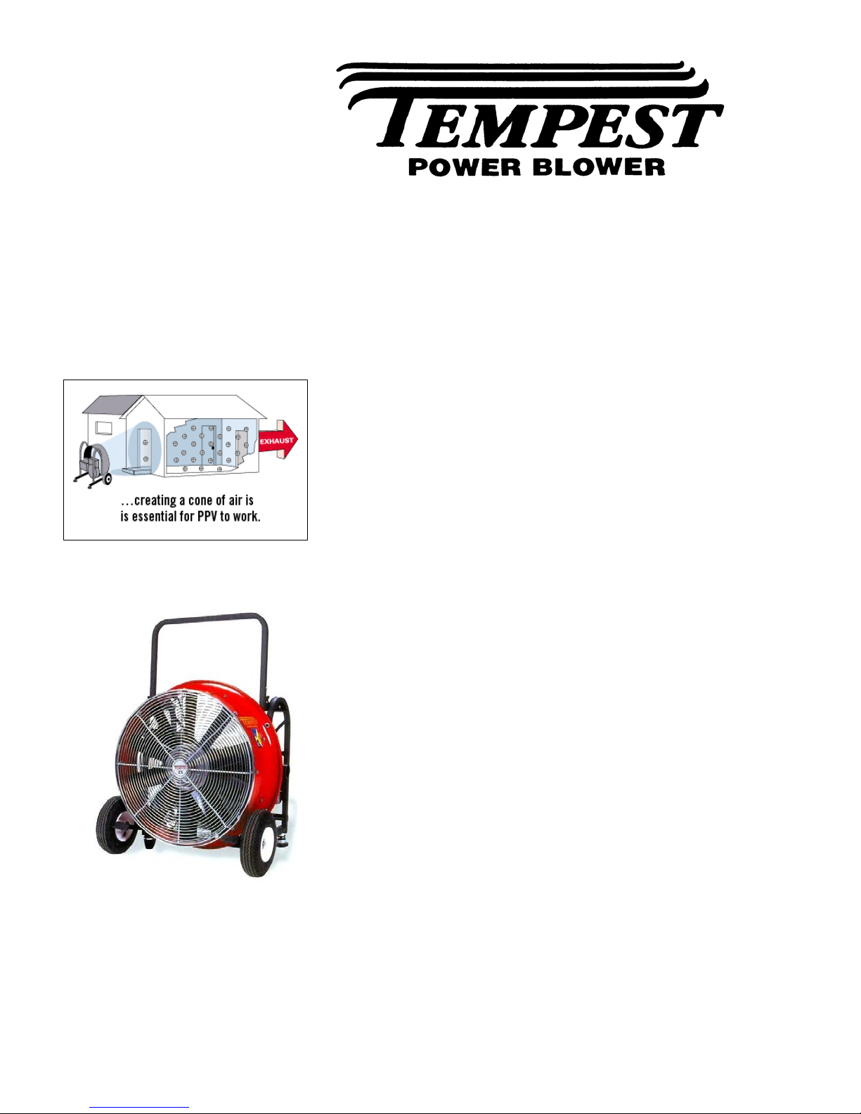
POWER BLOWER to provide “Positive
Pressure Ventilation”(PPV) to remove
heat, gases and smoke from the interior of
a burning structure.
TEMPEST has expanded into other
industries and found new applications for
its products. The ®TEMPEST POWER
BLOWER and PPV are used by
construction contractors to control dust,
fumes and unhealthy gases like carbon
monoxide; greatly improving safety in
confined spaces.
®TEMPEST TECHNOLOGY
CORPORATION has established a
reputation as a leader and innovator in the
air movement industry and continues in
that role today.

About This Manual
This manual is produced solely for the use of
purchasers and operators of ®TEMPEST
TECHNOLOGY CORPORATION equipment.
Any reproduction, retransmission, or other use of
the contents of this manual without written
consent of ®TEMPEST TECHNOLOGY
CORPORATION is strictly prohibited.
It is the intent of this manual to provide the
owner/operator of ®TEMPEST products with
both general and specific information regarding
the safe and proper operation and maintenance of
the equipment described within.
Contact
If after careful review, any questions arise
concerning any portion of this manual, contact
®TEMPEST TECHNOLOGY CORPORATION
for assistance at:
®TEMPEST TECHNOLOGY, INC.
4708 N. BLYTHE AVENUE
FRESNO, CA 93722
Phone (559) 277-7577 1 800-346-2143
FAX: (559) 277-7579
WEB PAGE: www.tempest-edge.com

Table of Contents
SAFETY PAGE
Safety Guide 2.1
GENERAL INFORMATION
Blower Identification 3.1
Warranty Card 3.2
Power Blower Data 3.3
Power Blower Information 3.6
OPERATION
Operating Procedures 4.1
Pre-Operation 4.1
Fuel, and Fuel Tank Capacities 4.2
Operation 4.3
Set-Up, Starting and Stopping Instructions 4.4
MAINTENANCE
Maintenance Procedures 5.1
Oil Change 5.1
Air Cleaner and Elements 5.2
Cooling System, Spark Plug 5.3
Emissions Control System 5.4
Belt Adjustment for Belt-Drive Power Blowers 5.4
Belt Replacement for Belt-Drive Power Blowers 5.5
Blade Removal 5.7
Blade Installation 5.8
Maintenance Schedule 5.8

PPV
PPV Set-up Procedures 6.1
Single Blower Placement 6.1
Multiple Blower Placement 6.2
Exhaust Opening 6.4
Weather Effects on PPV 6.6
TROUBLESHOOTING
Blower Troubleshooting 7.1
Blower Fails To Start 7.1
Poor Blower Performance 7.2
Blower Movement 7.2
PART NUMBERS
Honda Belt Drive Blowers 8.1
Honda Direct Drive Blowers 8.2
Tecumseh Belt Drive Blowers 8.3
Tecumseh Direct Drive Blowers 8.4
Briggs & Stratton Direct Drive Blowers 8.5
Bushings for Blade Replacement 8.6
BLOWER DRAWINGS
Direct Drive Units (Gas or Electric) 9.0
Belt Drive Unit 9.0
Pole Mount Unit (Electric) 9.0

Safety Guide
Safety Guide Failure to follow the operating, maintenance and
lubrication requirements set forth in this
Operation and Maintenance Manual may result in
serious personal injury and/or damage to
equipment.
The following WARNING statements indicate
potentially hazardous conditions for
operators and equipment. Make certain that
anyone who works on or around the blower
has read and fully understands the safety
precautions listed.
1. Carefully read this Operation and Maintenance
Manual before attempting to operate, service or
disassemble any part of your ®TEMPEST
POWER BLOWER.
2. Never operate the unit when mentally or
physically fatigued.
3. Stay away from rotating parts; avoid wearing
loose jackets, shirts, and ties. Keep hands and feet
away from the blower.
4. Keep all unauthorized personnel at a safe distance
from the blower.
5. Keep all guards in place. Never make repairs
while the unit is running. Never operate if any
guard or grill is not in place.
6. Always wear eye protection. Loose debris can be
picked up in the air stream and flown in the air.
Safety Guide 2.1

Safety Guide Continued…
7. Hearing protection is required. Motor and air
noise may exceed safe DB levels.
8. Gasoline is extremely flammable and is explosive
under certain conditions. To prevent fire hazards,
do not place flammable objects close to the
engine.
9. Do not overfill the fuel tank. After refueling,
make sure the tank cap is closed properly and
secured. If any fuel is spilled, make sure the area
is dry before starting the engine.
10. Never operate gasoline-powered blowers in an
enclosed or confined area. Exhaust contains
poisonous carbon monoxide gas; exposure may
cause loss of consciousness and may lead to
death.
11. The muffler becomes very hot during operation
and remains hot for some time after stopping the
engine. Be careful not to touch the muffler while
it is hot. To avoid severe burns or fire hazards, let
the engine cool before transporting or storing the
unit.
12. It is the sole responsibility of the owner/operator
to develop and practice the proper use of the
®TEMPEST POWER BLOWER in accordance
with generally accepted ventilation procedures as
well as the department’s own operating
procedures before placing the unit into service.
Safety Guide 2.2

General Information
Blower Identification
Each ®TEMPEST POWER BLOWER has a
model number as well as a serial number
(Figure 1.1). The model number signifies
information such as blade diameter, engine
type and horsepower. The serial number relates
to information referencing the date of
manufacture. This information is useful should
it become necessary to contact the factory
regarding your Power Blower.
PRODUCT
MODEL NO.
SERIAL NO.
TEMPEST TECHNOLOGY CORP.
Fi
g
ure 1.1
Please write the Serial Number of your
®TEMPEST POWER BLOWER in the spaces
below. This will aid us in identifying which
model you have when assisting you.
Model Number:
Serial Number: ____
Date Purchased:
Serial Number Locations
BELT-DRIVE and DIRECT DRIVE
GASOLINE POWERED UNITS: The serial
number is located on the side of the engine
housing.
ELECTRIC POWERED UNITS: The serial
number is located on a plate attached to the
motor.
General Information 3.1

Warranty
Be sure to fill out and return the warranty card
to TEMPEST TECHNOLOGY
CORPORATION in order to activate the
warranty. (Figure 1.2)
Figure 1.2
General Information 3.2

Power Blower Data
TYPE:
Positive Pressure Ventilator
BLADE:
Air Flex Fiberglass Reinforced Polyamide
High Strength Blades, Die Cast Aluminum
or Polypropylene.
BUSHING:
Keyed Shaft and Set or Cap Screws.
SHROUD:
Turbo 2000 Tapered Aluminum.
DRIVE:
Industrial-Type, Straight-Banded V-Belt
(On Belt-Drive Blowers) or Direct Drive
(On Direct Drive Blowers).
BEARINGS:
Locking, Self-Aligning and Permanently
Lubricated.
FRAME:
Rugged, Lightweight, Square-Steel Tubing
with Powder-Coat Finish.
TILT MECHANISM:
Patented Five-Positions, Foot-Operated Tilt
Mechanism (The Winning Step).
GRILL:
Continuous Circular-Wound, External-Weld
Steel Wire with 8 Tie Points for Additional
Safety.
General Information 3.3

Power Blower Data continued…
VIBRATION DAMPENERS:
Steel-Reinforced Rubber.
GAS ENGINES:
TYPE: Single Cylinder, 4 Stroke, Gasoline
COOLING: Forced Air
LUBRICATION: Splash Type Oil Reservoir
STARTING: Recoil with Auto Rewind
Belt Drive Gasoline Power Blowers
BELT-DRIVE
GAS ENGINE HP CFM S/B RPM WIDTH DEPTH HEIGHT LBS
BD 18-T-5.5 TECHUMSEH 5.5 10,903 8 4,070 21.50 21.00 24.25 79
BD 18-H-5.5 HONDA 5.5 15,023 5 3,870 21.50 21.00 24.25 85
BD 21-T-5.5 TECHUMSEH 5.5 18,673 9 3,350 25.00 22.00 26.25 87
BD 21-H-6.5 HONDA 6.5 17,743 5 3,125 25.00 22.00 26.25 93
BD 24-T-5.5 TECHUMSEH 5.5 17,314 6 3,190 28.25 22.00 31.00 86
BD 24-H-6.5 HONDA 6.5 18,130 5 3,175 28.25 22.00 31.00 92
BD 27-T-10 TECHUMSEH 10.0 23,690 10 2,643 30.50 23.50 32.50 137
BD 27-H-13 HONDA 13.0 23,943 10 2,672 30.50 23.50 32.50 155
Direct Drive Gasoline Power Blowers
DIRECT-
DRIVE GAS ENGINE HP CFM S/B RPM WIDTH DEPTH HEIGHT LBS
DD 16-T-5.5 TECHUMSEH 5.5 10,399 4 3,650 19.00 19.75 21.25 61
DD 16-H-5.5 HONDA 5.5 12,008 4 3,725 19.00 19.75 21.25 67
DD 18-T-5.5 TECHUMSEH 5.5 13,800 5 3,625 22.50 21.00 24.00 71
DD 18-H-5.5 HONDA 5.5 14,733 5 3,765 22.50 21.00 24.00 77
DD 21-B-5.5 BRIGGS 5.5 17,135 7 3,425 25.00 21.00 26.00 73
DD 21-T-5.5 TECHUMSEH 5.5 17,613 7 3,425 25.00 21.00 26.00 72
DD 21-H-6.5 HONDA 6.5 20,152 7 3,740 25.00 21.00 26.00 79
DD 24-B-5.5 BRIGGS 5.5 18,290 7 3,400 28.25 21.25 30.00 76
DD 24-T-5.5 TECHUMSEH 5.5 15,300 7 2,950 28.25 22.50 30.00 76
DD 24-H-6.5 HONDA 6.5 19,606 6 3,450 28.25 21.25 30.00 82
DD 36-B-5.5 BRIGGS 5.5 19,367 8 2,510 41.50 24.00 43.50 97
General Information 3.4

Power Blower Data continued…
ELECTRIC MOTORS:
All electric motors are single phase, 60
Hz, rigid base, 56 frame, with ball
bearings and manual reset overload
protection.
ELECTRIC
UNITS ENGINE HP CFM S/B RPM WIDTH DEPTH HEIGHT LBS
EB-12 ELECTRIC 1 TEFC 7,683 N.A. 3,450 16.00 19.50 21.50 45
EBS-16 ELECTRIC 1/3
TEFC 3,200 N.A. 1,736 18.75 14.25 19.50 47
EBS-16M
(W/MISTER) ELECTRIC 1/3
TEFC 3,200 N.A. 1,736 18.75 14.25 19.50 47
EB-16 ELECTRIC 1.5
TEFC 11,804 6 3,450 18.50 20.00 20.50 66
EB-18 ELECTRIC 1 TEFC 8,748 6 1,750 22.25 21.00 24.00 71
EB-21 ELECTRIC 1 TEFC 11,698 7 1,731 25.00 21.00 26.00 72
EB-24 ELECTRIC 1 TEFC 12,867 7 1,736 28.25 22.50 30.00 75
EB-36 ELECTRIC 1 TEFC 13,281 8 1,750 41.50 24.50 43.50 94
Electric Blower Power Requirements*
Based upon 115 v blower on a 20 amp circuit.
BLOWER MODEL MOTOR
HP STARTING
AMPS STARTING
WATTS RUNNING
AMPS RUNNING
WATTS
EB-12 1.0 48 6,000 16 1,900
EB-16 1.5 54.6 6,300 18.2 2,100
EBS-16 1/3 10.9 1,300 6.3 756
EB-18 1.0 48 6,000 16 1,900
EB-21 1.0 48 6,000 16 1,900
EB-24 1.0 48 6,000 16 1,900
EB-36 1.0 47.3 6,000 12.1 1,452
*Starting amps and watts are momentary
Maximum Power Cord Length (in feet)**
MOTOR H.P. 14 GAUGE 12 GAUGE 10 GAUGE 8 GAUGE 6 GAUGE
1/3 215’ 330’ 550’ 850’ 1,350’
1.0 60’ 95’ 150’ 240’ 380’
1.5 45’ 1.75’ 115’ 190’ 300’
**Calculations based upon one blower connected to 20 amp circuit.
General Information 3.5

Power Blower Information
The ®Tempest Power Blower is a high
powered, portable blower used for Positive
Pressure Ventilation (PPV), a ventilation
technique that quickly and efficiently replaces
hazardous interior environments.
PPV was pioneered in the fire fighting industry
where fire fighters use the ®Tempest Power
Blower to ventilate smoke, heat, and harmful
gases from buildings. This creates a safer
environment for them to work in and makes it
easier for them to find victims and extinguish
the fire.
Fi
g
ure 1.
3
PPV relies on two principles, (1) a cone shaped
air pattern, and (2) pressure. To accomplish
Positive Pressure Ventilation, the blower is
placed on the outside of the structure. It is
positioned so that the cone shaped air pattern
created by the blower completely seals the
entrance opening (Figure 1.3). When this seal
is achieved, the air pressure is increased
equally at all points inside the structure. When
General Information 3.6

Power Blower Information continued…
an exhaust opening is created, all of the interior
air moves in one mass towards it. The result is
fast, efficient ventilation of the entire structure.
For additional information on how to
accomplish PPV, refer to “PPV Set-Up
Procedures” in this Manual.
Note: The ®Tempest Power Blower is the most
efficient tool for PPV for two reasons. First,
the exclusive Tempest tapered shroud design
creates a wide, stable, conical air pattern.
Second, the seven blade air movement impeller
used on all Tempest blowers is designed to
create high pressure. These two features make
the ®Tempest Power Blower such a powerful
ventilation tool.
As with any new technique, Positive Pressure
ventilation requires training and education in
order to be implemented properly and safely.
Tempest offers a complete PPV TRAINING
PROGRAM, which covers many applications
of this powerful ventilation technique. For
more information contact your local dealer or
the Tempest factory direct for a free brochure
on PPV.
General Information 3.7

Operating Procedures
The information and instructions in this section
should be routinely reviewed and followed before
the actual operation of ®Tempest Power Blowers.
Pre-Operation
VISUAL INSPECTION
After receiving and unpacking your blower, be
sure to carefully inspect it for any damage that
might have occurred during shipping. Should you
find any damage: PLEASE NOTIFY TEMPEST
TECHNOLOGY IMMEDIATELY AT:
1-800-346-2143
ENGINE OIL
Be sure to use only high quality detergent oil.
Detergent oils keep the engine cleaner and retards
the formation of gum and varnish deposits.
RECOMMENDED OILS
HONDA engines: SF or SG SAE 10W-30 oil.
TECHUMSEH engines: SF, SG, SH, or SH/CD
SAE 30 oil
BRIGGS & STRATTON engines: SE, SF, SG
SAE 30 oil
Operating Procedures 4.1

Pre-Operation continued…
OIL SUMP CAPACITIES
ENGINE CAPACITY QUARTS / LITRES
BRIGGS 5.5 HP 20 FL. OZ. .66 QUARTS OR .59 LITERS
HONDA GX160 5.5 HP 20 FL. OZ. .63 QUARTS OR .6 LITERS
HONDA GX200 6.5 HP 20 FL. OZ. .63 QUARTS OR .6 LITERS
HONDA GX390 13 HP 37 FL. OZ. 1.16 QUARTS OR .77 LITERS
TECHUMSEH OHH5 5.5HP 21 FL. OZ. .66 QUARTS OR .62 LITERS
TECHUMSEH HM100 10 HP 26 FL. OZ. .81 QUARTS OR .77 LITERS
FILLING THE CRANKCASE
Place blower on a level surface and make sure that
the engine is level. Remove the oil fill plug or
dipstick. POUR OIL SLOWLY into the
crankcase. Replace oil fill plug or dipstick and
tighten securely. Refer to the engine
manufacturers Owners Manual for additional
information regarding specific oil requirements.
CAUTION: DO NOT OVERFILL THE ENGINE.
EXCESS OIL VAPOR CAN BE EJECTED
FROM THE ENGINE BREATHER WHILE
RUNNING IN FULL TILT POSITION.
FUEL
Always use clean, fresh, lead-free gasoline with
an octane rating of 86 or higher. DO NOT USE
leaded gasolines. Refer to the engine
manufacturers Owners Manual for acceptable
substitute gasolines.
Operating Procedures 4.2

Pre-Operation continued…
CAUTION: PRECAUTIONS MUST BE
FOLLOWED WHENEVER REFUELING
GASOLINE ENGINES. PLEASE FOLLOW
THE LISTED GUIDELINES.
NEVER FILL THE FUEL TANK INDOORS.
NEVER FILL THE FUEL TANK WHILE THE
ENGINE IS RUNNING OR HOT.
DO NOT SMOKE DURING REFUELING.
NEVER FILL THE FUEL TANK COMPLETELY.
FILL THE TANK TO BOTTOM OF FILLER
NECK TO PROVIDE SPACE FOR FUEL
EXPANSION.
WIPE ANY SPILLAGE FROM ENGINE AND
COMPONENTS BEFORE STARTING THE
ENGINE.
FUEL TANK CAPACITY
ENGINE CAPACITY QUARTS / LITRES
BRIGGS 5.5 HP 96 FL. OZ. 3 QUARTS OR 2.85 LITERS
HONDA GX160 5.5 HP 121.6 FL. OZ. 3.8 QUARTS OR 3.6 LITERS
HONDA GX200 6.5 HP 121.6 FL. OZ. 3.8 QUARTS OR 3.6 LITERS
HONDA GX390 13 HP 192 FL. OZ. 6 QUARTS OR 6.34 LITERS
TECHUMSEH OHH5 5.5HP 64 FL. OZ. 2 QUARTS OR 2.11 LITERS
TECHUMSEH HM100 10 HP 128 FL. OZ. 4 QUARTS OR 4.22 LITERS
Operation
SET-UP, STARTING AND STOPPING
Assuming the previous Pre-Operation instructions
have been followed the blower is now ready to
Operating Procedures 4.3

Operation continued…
run. Please review the engine manufacturers
Owners Manual regarding starting and stopping as
well as the instructions in this section before
actually starting the blower.
CAUTION: NEVER MOVE THE BLOWER
WHILE IT IS IN OPERATION. SEVERE
PERSONAL INJURY IS POSSIBLE AS WELL
AS DAMAGE TO THE BLOWER.
ALWAYS SHUT-DOWN THE BLOWER
PRIOR TO MOVING!
SET-UP
Position the blower in the desired location,
making sure it is placed on a flat, hard and debris
free surface.
STARTING
1. Set the fuel valve in the “ON” position.
2. Set the stop switch to the “ON” position.
3. Set (if equipped) the choke lever to the
“CLOSED” or “STARTING” position.
4. Set the throttle lever to the “STARTING”
position.
5. Grasp the starter handle, take up the slack, and
pull the rope briskly. Let the rope return slowly.
Repeat as necessary until the engine starts. Do not
over pull the rope.
Operating Procedures 4.4

6. If equipped with a choke, move the choke lever to
the ½ position until the engine runs smoothly and
then to the open or off position.
7. Move the throttle to the desired speed. NOTE:
Some blowers may tend to “walk” if the throttle is
not in the full position.
STOPPING
1. Move the throttle to the “IDLE” position.
2. Move throttle lever to the “OFF” position unless
equipped with a stop switch. If a stop switch is
provided, turn the switch to the “OFF” position.
Operating Procedures 4.5

Maintenance Procedures
Proper maintenance is necessary to ensure that
your ®Tempest Power Blower operates as
efficiently and trouble-free as possible. By
following the instructions in this section you will
be providing the maintenance needed to achieve
this goal.
CAUTION: THE ENGINE MAY START
SIMPLY BY ROTATING THE BLADES.
ALWAYS REMOVE THE SPARK PLUG WIRE
PRIOR TO WORKING ON THE BLADE SIDE
OF THE MOTOR.
OIL CHANGE
Oil Filler Ca
p
Check the engine oil level before each use. The
oil should be changed after the first three (3)
operating hours and every 50 hours thereafter. Oil
changes should be performed more frequently if
the blower is being operated in dusty or dirty
conditions. Changing the oil is easier when the
engine is still warm (not hot) from a recent
running.
PROCEDURES
1. Position the blower so the engine oil drain plug
is the lowest point on the engine.
2. Place a two quart or larger container under the oil
drain plug for the oil to drain into.
3. Remove the oil drain plug.
4. Install the oil drain plug and tighten securely.
Maintenance 5.1
Table of contents
Other Tempest Blower manuals

Tempest
Tempest Direct-Drive User manual

Tempest
Tempest LAMINAR ELECTRIC - LE User manual

Tempest
Tempest VS1-18-BLDC User manual

Tempest
Tempest SP Power Blower User manual

Tempest
Tempest BD-21-H-6.5 User manual

Tempest
Tempest VSG User manual

Tempest
Tempest Power Blower Direct-Drive Series User manual

Tempest
Tempest BB-16 User manual

Tempest
Tempest VSM Series User manual
Popular Blower manuals by other brands

Worx Nitro
Worx Nitro LEAFJET WG543E Safety and operating manual original instructions

Ebmpapst
Ebmpapst D2E146-AP43-78 operating instructions

Ebmpapst
Ebmpapst G1G126-AB13-13 operating instructions

IKRAmogatec
IKRAmogatec Gartenmeister GM ALB 40 operating instructions

BLACK DECKER
BLACK DECKER BEBLV230 manual

sunjoe
sunjoe SBJ597E Operator's manual