Tempest Tornado Marine G4 User manual

Tornado G4 User Manual 1
User Manual
Tornado G4
Tornado Marine G4
Revision 01.4
August 2017
© Tempest Lighting, Inc.

Tornado G4 User Manual 2
Table of Contents
Table of Contents........................................................................................................................................................................................ 2
Approvals –North America.................................................................................................................................................................... 4
Approvals –Europe ................................................................................................................................................................................ 5
Approvals –China ................................................................................................................................................................................... 6
Introduction ................................................................................................................................................................................................ 7
IMPORTANT: Safety Advisories.............................................................................................................................................................. 7
Installation................................................................................................................................................................................................... 8
Dimensions, Rigging Points, and Maximum Luminaire Dimensions/Power........................................................................................ 8
Airflow Clearance ............................................................................................................................................................................. 10
Snow Clearance ................................................................................................................................................................................ 10
Mounting Hardware Options ............................................................................................................................................................... 11
Mounting Bolts ................................................................................................................................................................................. 11
Globe Down Tornado Enclosures .................................................................................................................................................... 11
Horizontal Tornado Enclosures........................................................................................................................................................ 11
Drainage ................................................................................................................................................................................................ 12
Wiring the Enclosure ................................................................................................................................................................................ 13
Power Wiring ........................................................................................................................................................................................ 13
SAFETY NOTICE ................................................................................................................................................................................. 13
Electrical Standards .......................................................................................................................................................................... 13
Wiring Access –Globe-up Models................................................................................................................................................... 13
Wiring Access –Globe-down and Horizontal Models .................................................................................................................... 14
One or Two Power Circuits? ............................................................................................................................................................ 15
Single Feed Power Termination....................................................................................................................................................... 16
Split Feed Power Termination ......................................................................................................................................................... 16
AC Supply Voltage............................................................................................................................................................................. 16
Wiring –North America/Japan 200-208VAC .................................................................................................................................. 17
Wiring –International 220-250VAC ................................................................................................................................................ 18
Remote Monitoring Connections ........................................................................................................................................................ 19
Direct Ethernet Monitoring Network .............................................................................................................................................. 20
RS485 to Ethernet TEMP Monitoring Network............................................................................................................................... 21
DMX/RDM Monitoring Network...................................................................................................................................................... 22
RS485 (DMX/RDM) Cable Terminations.......................................................................................................................................... 23
Luminaire Power Control using DMX512........................................................................................................................................ 23
Digital Enclosure Control.......................................................................................................................................................................... 24
Schematic.............................................................................................................................................................................................. 24
DEC4 Main Functions ........................................................................................................................................................................... 25

Tornado G4 User Manual 3
Factory Settings –Basic Mode............................................................................................................................................................. 25
Other Operating Modes ....................................................................................................................................................................... 26
Monitor Mode .................................................................................................................................................................................. 26
Control Mode.................................................................................................................................................................................... 26
Service Mode .................................................................................................................................................................................... 26
DEC4 Control Parameters .................................................................................................................................................................... 27
Control Interface .............................................................................................................................................................................. 28
User Interface LCD Display............................................................................................................................................................... 29
Control Interface Operation ............................................................................................................................................................ 29
Control Menu........................................................................................................................................................................................ 30
Set DMX Options .............................................................................................................................................................................. 30
Set Temp Units ................................................................................................................................................................................. 31
Set Temp Ranges .............................................................................................................................................................................. 31
Set Lamp On Point............................................................................................................................................................................ 31
Reset Lamp Hours............................................................................................................................................................................. 31
Status Display.................................................................................................................................................................................... 32
Mounting the Luminaire........................................................................................................................................................................... 33
Luminaire Base Handles ....................................................................................................................................................................... 33
Mounting Bars ...................................................................................................................................................................................... 34
Mounting The Luminaire...................................................................................................................................................................... 35
Omega Clamps.................................................................................................................................................................................. 36
Screws ............................................................................................................................................................................................... 37
Quarter-Turn Fasteners (QTF) ......................................................................................................................................................... 38
Install Luminaire in the Tornado Base............................................................................................................................................. 39
Vari-Lite Truss Adapters ................................................................................................................................................................... 40
Connect Luminaire Power................................................................................................................................................................ 41
Routine Maintenance ............................................................................................................................................................................... 42
Clean Acrylic Globe........................................................................................................................................................................... 42
Check Filter ....................................................................................................................................................................................... 42
Check Temperature/Humidity Sensor............................................................................................................................................. 43
For After Sales Support .................................................................................................................................................................... 43
Troubleshooting........................................................................................................................................................................................ 44
Warranty ................................................................................................................................................................................................... 46
Appendix –TEMP Protocol....................................................................................................................................................................... 47
Physical Layer........................................................................................................................................................................................ 47
Developer’s Guide ................................................................................................................................................................................ 47

Tornado G4 User Manual 4
Approvals –North America
This is to certify that the following products:
55.xxx.US Series Tornado G4 Luminaire Enclosures
Have been tested and approved to standards UL 508 (electrical) and UL 50 (environmental), as NEMA 3R enclosures,
for use in the United States and Canada.
This declaration is made by the manufacturer
Tempest Lighting, Inc.
11845 Wicks Street, Sun Valley, CA 91352, USA
This declaration is based on tests that were conducted on the submitted samples of the above mentioned products.
Listing Report No. 3198609LAX-001a refers.
Dated: July 1st , 2016
Signature . . . . . . . . . . . . . .
Tempest Lighting Inc

Tornado G4 User Manual 5
Approvals –Europe
CERTIFICATE AND DECLARATION OF CONFORMITY
FOR CE MARKING
Tempest Lighting, Inc.
11845 Wicks Street, Sun Valley, CA 91352 , USA
t: +1 818 787 8984 f: +1 818 252 7101 e: info@tempest.biz
www.tempest.biz
Tempest Lighting, Inc. declares that t heir
Tornado G4 Luminaire Enclosure Series 55.xxx.xx
complies with the Essential Requirements of the following EU Directives:
Low Voltage Directive 2006/95/EC Test Report G4.51.LVD
Electromagnetic Compatibility Directive 2004/108/EC Test Report G4.51.EMC
and further conforms with the following EU Harmonized Standards:
EN 60065 : 2002 Test Report 60065.G4.51.01
EN 60529:2001-2002 Test Report 60529.G4.51.02
EN 61000-6-3:2007+A1:2011 Test Report 61000.G4.51.03
EN61000-6-1:2007 Test Report 61000.G4.51.03
EN55015:2006+A2:2009 Test Report 61000.G4.51.03
Dated: 1s t July 2016
Position of signatory: President
Name of Signatory: Tim Burnham
Signed below:
on behalf of Tempest Lighting, Inc.
. . . . . . . . . . . . . . . . . . . . . . . . . . . . .

Tornado G4 User Manual 6
Approvals –China

Tornado G4 User Manual 7
Introduction
Thank you for purchasing a Tempest enclosure! We have worked hard to provide you with the very
best product available for its purpose, and we shall continue to do everything possible to ensure that
it works well for you for many years to come.
Please read this manual before starting work!
In the event of difficulty, please contact your Tempest reseller or Tempest direct:
+1 818 787 8984
We will do everything we can to help you get the very best results from your Tempest enclosure.
IMPORTANT: Safety Advisories
All installation and rigging work done must where applicable be designed and built in
accordance with norms and standards of the local authority having jurisdiction of the
installation site. It is the responsibility of the installer to obtain such approvals as may be
required to achieve full compliance.
All electrical work must be carried out by a suitably licensed electrical contractor in full
compliance with local electrical standards.
Lifting: some enclosures and the equipment inside them may be heavy. Use properly rated
lifting equipment where appropriate and never attempt to carry out work with fewer than
the number of workers needed to lift safely.
It is the responsibility of the installer to ensure that all local building, safety and electrical
codes are strictly adhered to in the installation of this enclosure. Tempest Lighting, Inc., its
employees and agents are in no way responsible for damage arising from failure to follow
either the instructions in this manual or building, safety and electrical codes prevailing at
the installation location.
Do not attempt to install or operate the enclosure before fully reading and understanding
this manual
Never allow anyone who has not read this manual to open the enclosure or perform
maintenance on the luminaire within.
Never leave the enclosure unattended when open.
Always make sure all bolts and latches are tight and safety locks are in place after
performing any form of maintenance on the unit.
Do not open any electrical boxes until power has been shut off to all supply lines to the
enclosure (including the one powering the luminaire).
Do not open the enclosure in wet weather.

Tornado G4 User Manual 8
Installation
Dimensions, Rigging Points, and Maximum Luminaire Dimensions/Power
Model #
Description
A
Height
B
Diameter
C
Mounting
Centers
D
Mounting
Centers
Weight
Lbs/kg
E
Luminaire
Max Height
F
Luminaire
Max Width
G
Luminaire
Base Width
Luminaire
Max Watts
1850.xxG
Tornado 1850
32”/813
23”/584
11.95”/304
21”/533
42/19
16.5”/420
16”/410
14.5”/370
500W
1850.xxGV
Tornado 1850
33”/838
30”/762
11.95”/304
23”/584*
45/21
16.5”/420
16”/410
14.5”/370
500W
1850.xxGH
Tornado 1850
33”/838
30”/762
11.95”/304
23”/584*
46/21
16.5”/420
16”/410
14.5”/370
500W
1850.xxM
Tornado Marine 1850
33”/838
23”/584
11.95”/304
21”/533
42/19
16.5”/420
16”/410
14.5”/370
500W
1850.xxMV
Tornado Marine 1850
34”/864
30”/762
11.95”/304
23”/584*
45/21
16.5”/420
16”/410
14.5”/370
500W
1850.xxMH
Tornado Marine 1850
34”/864
30”/762
11.95”/304
23”/584*
46/21
16.5”/420
16”/410
14.5”/370
500W
1900.xxG
Tornado 1900
38”/965
24”/610
11.95”/304
21”/533
52/24
24.5”/620
16”/410
14.5”/370
600W
1900.xxGV
Tornado 1900
39”/991
30”/762
11.95”/304
23”/584*
60/27
24.5”/620
16”/410
14.5”/370
600W
1900.xxGH
Tornado 1900
39”/991
30”/762
11.95”/304
23”/584*
60/27
24.5”/620
16”/410
14.5”/370
600W
1900.xxM
Tornado Marine 1900
39”/991
24”/610
11.95”/304
23”/584*
52/24
24.5”/620
16”/410
14.5”/370
600W
1900.xxMV
Tornado Marine 1900
40”/1016
30”/762
11.95”/304
23”/584*
60/27
24.5”/620
16”/410
14.5”/370
600W
1900.xxMH
Tornado Marine 1900
40”/1016
30”/762
11.95”/304
23”/584*
60/27
24.5”/620
16”/410
14.5”/370
600W
1925.xxG
Tornado 1925
42”/1070
27”/690
11.95”/304
21”/533
52/24
28”/710
16”/410
14.5”/370
600W
1925.xxGV
Tornado 1925
43”/1090
30”/762
11.95”/304
23”/584*
60/27
28”/710
16”/410
14.5”/370
600W
1925.xxGH
Tornado 1925
43”/1090
30”/762
11.95”/304
23”/584*
60/27
28”/710
16”/410
14.4”/370
600W
Rigging Points –Globe Up:
Use M12 stainless steel bolts (supplied with
shipping pallet) to attach to structure
Rigging Points –Globe Down/Horizontal:
Use M12 stainless steel bolts and Spring
Nuts (supplied with shipping pallet) to
attach Unistrut rails to structure
Base Width (G): It may be
necessary to remove base
handles for some
luminaires.

Tornado G4 User Manual 9
Model #
Description
A
Height
B
Diameter
C
Mounting
Centers
D
Mounting
Centers
Weight
Lbs/kg
E
Luminaire
Max Height
F
Luminaire
Max Width
G
Luminaire
Base Width
Luminaire
Max Watts
1925.xxM
Tornado Marine 1925
43”/1090
27”/690
11.95”/304
21”/533
52/24
28”/710
16”/410
14.5”/370
600W
1925.xxMV
Tornado Marine 1925
44”/1118
30”/762
11.95”/304
23”/584*
60/27
28”/710
16”/410
14.5”/370
600W
1925.xxMH
Tornado Marine 1925
44”/1118
30”/762
11.95”/304
23”/584*
60/27
28”/710
16”/410
14.5”/370
600W
1975.xxG
Tornado 1975
45”/1150
27”/690
11.95”/304
21”/533
57/26
30.5”/780
16”/410
14.5”/370
600W
1975.xxGV
Tornado 1975
46”/1168
30”/762
11.95”/304
23”/584*
65/30
30.5”/780
16”/410
14.5”/370
600W
1975.xxGH
Tornado 1975
46”/1168
30”/762
11.95”/304
23”/584*
65/30
30.5”/780
16”/410
14.5”/370
600W
1975.xxM
Tornado Marine 1975
46”/1168
23”/584
11.95”/304
21”/533
57/26
30.5”/780
16”/410
14.5”/370
600W
1975.xxMV
Tornado Marine 1975
47”/1194
30”/762
11.95”/304
23”/584*
65/30
30.5”/780
16”/410
14.5”/370
600W
1975.xxMH
Tornado Marine 1975
47”/1194
30”/762
11.95”/304
23”/584*
65/30
30.5”/780
16”/410
14.5”/370
600W
2000.xxG
Tornado 2000
45”/1150
32”/820
16.23”/412
28.5”/724
110/50
30.5”/780
21”/530
19.25”/490
1200W
2000.xxGV
Tornado 2000
39”/991
36”/914
16.23”/412
30”/762*
115/55
30.5”/780
21”/530
19.25”/490
1200W
2000.xxGH
Tornado 2000
39”/991
36”/914
16.23”/412
30”/762*
115/55
30.5”/780
21”/530
19.25”/490
1200W
2000.xxM
Tornado Marine 2000
39”/991
32”/820
16.23”/412
28.5”/724
110/50
30.5”/780
21”/530
19.25”/490
1200W
2000.xxMV
Tornado Marine 2000
40”/1016
36”/914
16.23”/412
30”/762*
115/55
30.5”/780
21”/530
19.25”/490
1200W
2000.xxMH
Tornado Marine 2000
40”/1016
36”/914
16.23”/412
30”/762*
115/55
30.5”/780
21”/530
19.25”/490
1200W
2300.xxG
Tornado 2300
53”/1350
36”/914
16.23”/412
28.5”/724
111/51
38”/970
21”/530
19.25”/490
1700W
2300.xxGV
Tornado 2300
54”/1370
36”/914
16.23”/412
30”/762*
126/57
38”/970
21”/530
19.25”/490
1700W
2300.xxGH
Tornado 2300
54”/1370
36”/914
16.23”/412
30”/762*
126/57
38”/970
21”/530
19.25”/490
1700W
2360.xxG
Tornado 2360
53”/1350
36”/914
16.23”/412
28.5”/724
111/51
38”/970
VL6000-specific
2360.xxGV
Tornado 2360
54”/1370
36”/914
16.23”/412
30”/762*
126/57
38”/970
VL6000-specific
2360.xxGH
Tornado 2360
54”/1370
36”/914
16.23”/412
30”/762*
126/57
38”/970
VL6000-specific
2300.xxM
Tornado Marine 2300
54”/1370
36”/914
16.23”/412
28.5”/724
111/51
38”/970
21”/530
19.25”/490
1700W
2300.xxMV
Tornado Marine 2300
55”/1397
36”/914
16.23”/412
30”/762*
126/57
38”/970
21”/530
19.25”/490
1700W
2300.xxMH
Tornado Marine 2300
55”/1397
36”/914
16.23”/412
30”/762*
126/57
38”/970
21”/530
19.25”/490
1700W
2400.xxG
Tornado 2400
61”/1530
42”/1067
19.48”/495
34.50”/87
6
204/93
44”/1120
28”/710
24.25”/615
2500W
2400.xxGV
Tornado 2400
62”/1575
42”/1067
19.48”/495
36”/914*
209/95
44”/1120
28”/710
24.25”/615
2500W
2400.xxM
Tornado Marine 2400
61”/1530
42”/1067
19.48”/495
34.50”/87
6
204/93
44”/1120
28”/710
24.25”/615
2500W
2400.xxMV
Tornado Marine 2400
62”/1575
42”/1067
19.48”/495
36”/914*
209/95
44”/1120
28”/710
24.25”/615
2500W
2500.xxG
Tornado 2500
67”/1700
48”/1220
19.48”/495
34.50”/87
6
209/95
52”/1320
28”/710
24.25”/615
3000W
2500.xxGV
Tornado 2500
68”/1725
48”/1220
19.48”/495
36”/914*
214/97
52”/1320
28”/710
24.25”/615
3000W
2500.xxM
Tornado Marine 2500
67”/1700
48”/1220
19.48”/495
34.50”/87
6
209/95
52”/1320
28”/710
24.25”/615
3000W
2500.xxMV
Tornado Marine 2500
68”/1725
48”/1220
19.48”/495
36”/914*
214/97
52”/1320
28”/710
24.25”/615
3000W

Tornado G4 User Manual 10
Airflow Clearance
Observe the minimum clearances shown around your
enclosure
Snow Clearance
In areas where snow is likely, make sure the base of the
enclosure is at least 24” [60cm] above highest potential
snow drift level.
60cm/24in
Tornado G4 User Manual 11
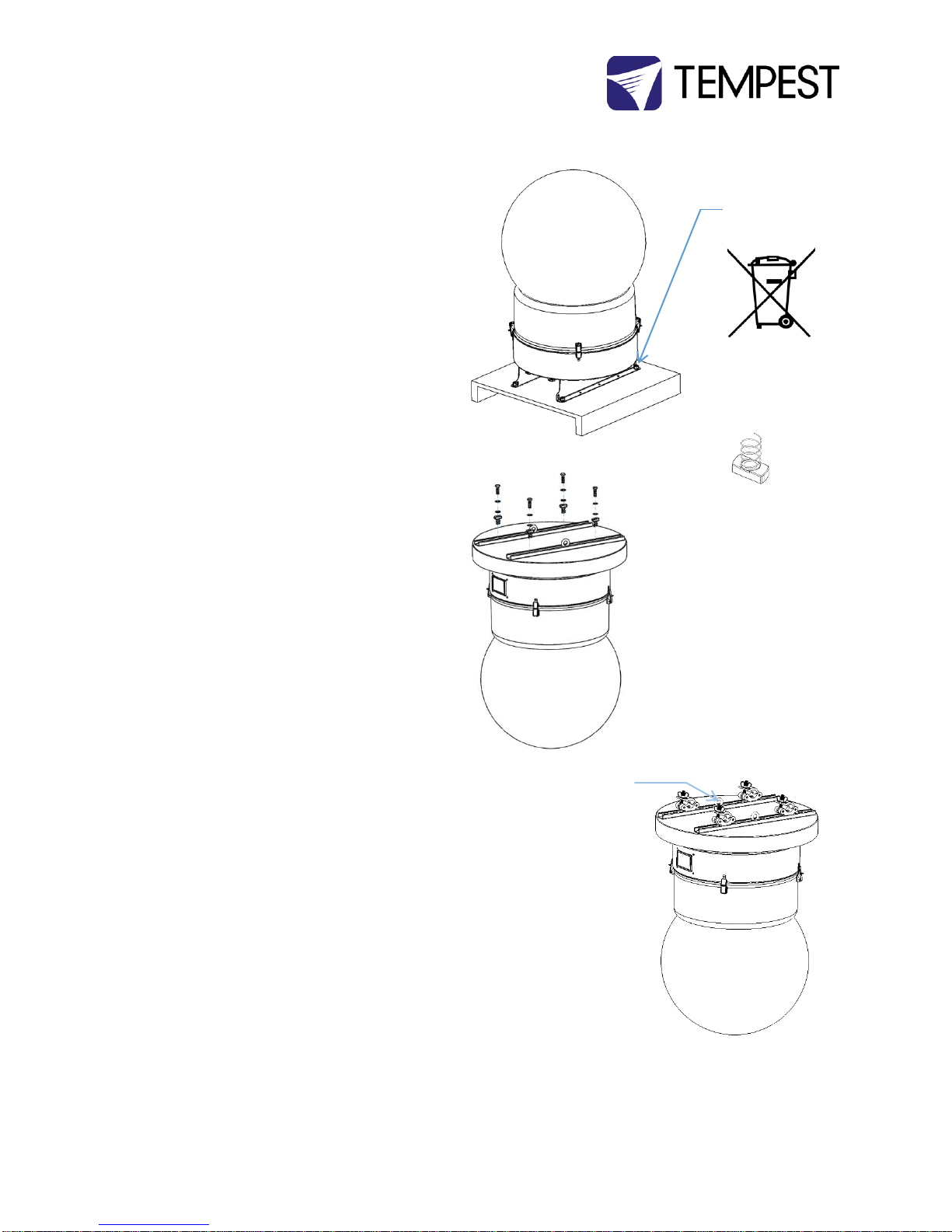
Mounting Hardware Options
Mounting Bolts
1. DO NOT DISCARD THE BOLTS ATTACHING THE
ENCLOSURE TO THE SHIPPING PALLET
2. Each Enclosure must be mounted with FOUR points.
3. Mountings must be made using M12 or ½” bolts
4. Tempest recommends the use of stainless steel
mounting hardware.
5. Bolt enclosure to a stable structure capable of
supporting the weight of the enclosure plus the
luminaire enclosed.
Globe Down Tornado Enclosures
6. Bolt the Tornado enclosure to a suitable overhead
structure using the bolts and Unistrut spring nuts
supplied
7. To hang from a lighting truss, use four hanging clamps
or half-couplers, bolted to Unistrut spring nuts
8. Screw the eyebolts supplied into the center threaded
holes in the Unistruts and secure to the overhead
structure or truss with a safety cable (not supplied)
rated for 5 x the total weight of the Tornado enclosure
plus luminaire.
Horizontal Tornado Enclosures
9. Bolt the Tornado enclosure to a suitable overhead
structure using the bolts and Unistrut spring nuts
supplied –see illustration (6).
IMPORTANT SAFETY NOTICE
Installer must ensure that all mounting points are secure
and conform to local safety regulations. Tempest Lighting
Inc. accepts no responsibility for damage or injury arising
from inappropriate or unsafe installation.
M12-1.75 x 40 bolts,
washers, nuts
DO NOT DISCARD!
NOTE:
Globe Down and
Horizontal enclosures
also supplied with
Unistrut Spring nuts.
Use the M12 bolts,
washers and Unistrut
spring nuts provided to
attach globe-down
Tornado enclosures to a
suitable overhead
support.
Attach hanging
clamps or half
couplers to the
Unistrut rails to
hang Tornado from
a lighting truss
Safety cable Eyebolts
Tornado G4 User Manual 12
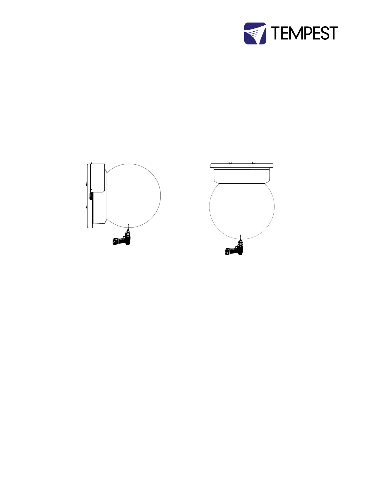
Drainage
For base up/globe down or horizontal operation, a small drainage hole should be drilled in the globe, to permit any water
draining through the enclosure to exit harmlessly.
Note: this is not required in sheltered installations, such as under an overhang or canopy.
YOU MUST USE THE APPROPRIATE TAPERED DRILL BIT.
A tapered drill bit is included with the printed manual packet in each Tornado shipment.
Replacements are available from Tempest free of charge.
A standard drill bit may crack the plexiglass globe. Tempest Lighting will not be responsible for such damage.
Horizontal Enclosures –be sure to replace the globe with the drainage hole at the lowest point after relamping.

Tornado G4 User Manual 13
Wiring the Enclosure
Power Wiring
SAFETY NOTICE
All power wiring must be performed by a competent electrician, appropriately licensed in the jurisdiction where the installation takes
place. All electrical work must be done in full compliance with all electrical and safety norms applicable to the installation site. Isolate
all power feeds before opening the enclosure.
Tempest Lighting, Inc., its employees and agents will not be held responsible for damage or injury caused by disregarding this notice.
Electrical Standards
Important:
Enclosure model numbers including .US are for use in countries using US and Japanese style electrical systems:
200-208VAC 50/60Hz
Enclosure model numbers including .IN are for use in countries using European style electrical systems:
220-250VAC 50/60Hz
Note:
(1) All Tornado and Tornado Marine G4 exhaust fans are 120VAC, regardless of electrical standard. The control electronics
provide a variable ac supply to the exhaust fans up to 120V.
(2) Heaters are rated 200-250V, dependent on electrical standard.
(3) Electronics are autosensing for any voltage 90-265VAC, 50/60Hz
(4) Tornado enclosures may be supplied wired for 120V operation to special order.
Wiring Access –Globe-up Models
Locate the two Conduit entry holes on the underside of
the enclosure:
Conduit openings accept PG21 (International) and ¾” NPT
(North America) conduit fittings.
Use permanent or flexible, outdoor rated, conduit to
connect power and signal cables to your Tornado
enclosure.
ALWAYS RUN POWER AND SIGNAL CABLES IN SEPARATE
CONDUITS.
Conduit Entry:
SIGNAL
Conduit Entry:
AC POWER

Tornado G4 User Manual 14
Wiring Access –Globe-down and
Horizontal Models
Locate the two Conduit entry holes on the enclosure rain
guard:
Conduit openings accept PG21 (International) and ¾” NPT
(North America) conduit fittings.
USE LIQUID-TIGHT CONDUIT FITTINGS OR CABLE GLANDS.
Use permanent or flexible, outdoor rated conduit to
connect power and signal cables to your Tornado
enclosure.
Use the plastic sleeves supplied to protect cables
between the conduit fittings and the internal wiring
terminals.
ALWAYS RUN POWER AND SIGNAL CABLES IN SEPARATE
CONDUITS.
Remove the DEC4 Controller cover.
Conduit Entry:
AC POWER
Conduit Entry:
SIGNAL
Cover
Thumbscrews
DEC4 Cover
Flexible Conduit
with watertight
fittings
Plastic Sleeve
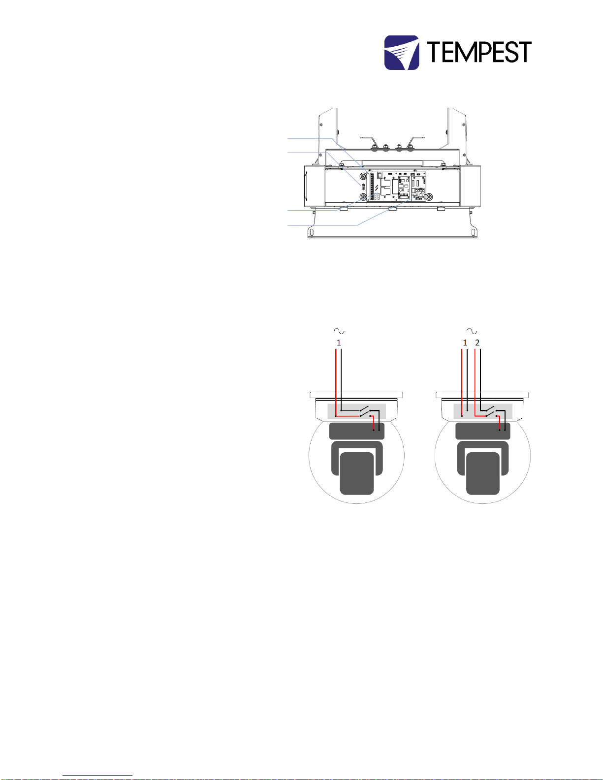
Tornado G4 User Manual 15
Identify the following parts:
AC Terminal Block
Earth/Ground Terminal
DEC4 Motherboard
DEC4 Daughter Board(s)
Up to 3 daughter boards: types include Fan Control,
RS485 Comms, Ethernet
(CUTAWAY VIEW)
One or Two Power Circuits?
Tempest enclosures may be wired on single or double
circuit supplies. On a single feed, both enclosure and
luminaire are permanently on. With a split (double) feed
supply, you can switch off the luminaire when not in use,
while the enclosure continues to protect it 24/7.
Tip: most people use single feed.
Tip: even wired for single feed, you can use DMX to switch
the luminaire power on and off –see the DEC4 section
below.
Single Feed
Enclosure and luminaire are permanently on.
Enclosure and Luminaire must be rated for the
same voltage.
Supply must be rated for luminaire current plus
150 watts.
Supply must be permanently ON.
Split feed
Enclosure power must be permanently ON.
Luminaire power may be switched off.
Enclosure power must be rated for:
oTornado 1850-1975: 650 watts
oTornado 2000-2300: 1150 watts
oTornado 2400-2500: 2000 watts
Luminaire power must be rated for the luminaire (see
luminaire manual).
Single Feed
Split Feed
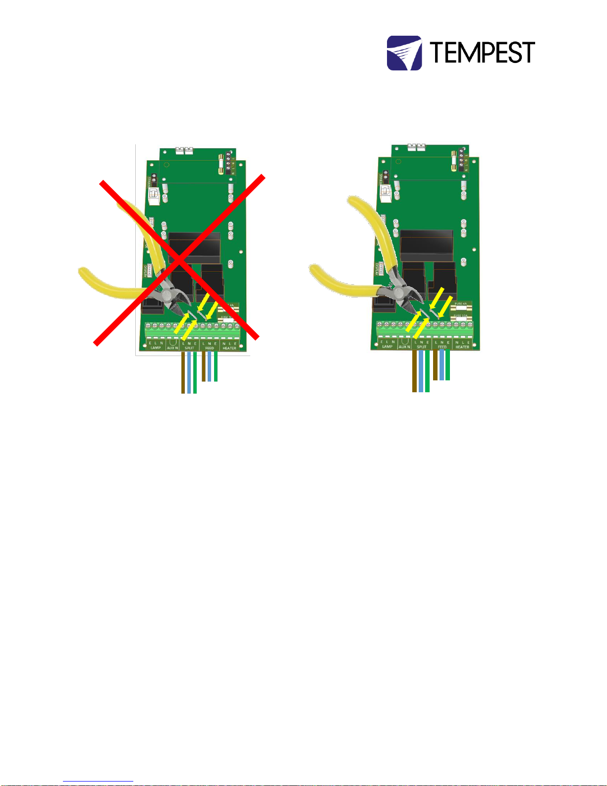
Tornado G4 User Manual 16
For single feed wiring, no modification to the DEC4
Controller motherboard is needed.
IMPORTANT:
For split feed wiring, use a side cutter to cut both AC links at both
ends:
Single Feed Power Termination
Connect Earth/Ground wire to Ground Terminal
Connect Live and Neutral to the terminals marked
FEED
Split Feed Power Termination
STOP! Did you cut the power links? See above.
Connect Earth/Ground wire to Ground Terminal
Connect Enclosure feed to the terminals marked FEED
Connect Luminaire feed to the terminals marked SPLIT
SEE WIRING DIAGRAMS BELOW
AC Supply Voltage
Tempest Tornado enclosures require supply voltage in
the nominal range 200-250VAC, 50/60Hz.
North American installations –use a 208V
supply (2 x 120V hots), and connect one hot to
Line and one to Neutral terminals.
North American 120V versions are available to
special order.

Tornado G4 User Manual 17
Wiring –North America/Japan 200-208VAC
Note: For clarity, internal wiring is not shown.
Single Feed
Split Feed
Tornado G4 User Manual 18
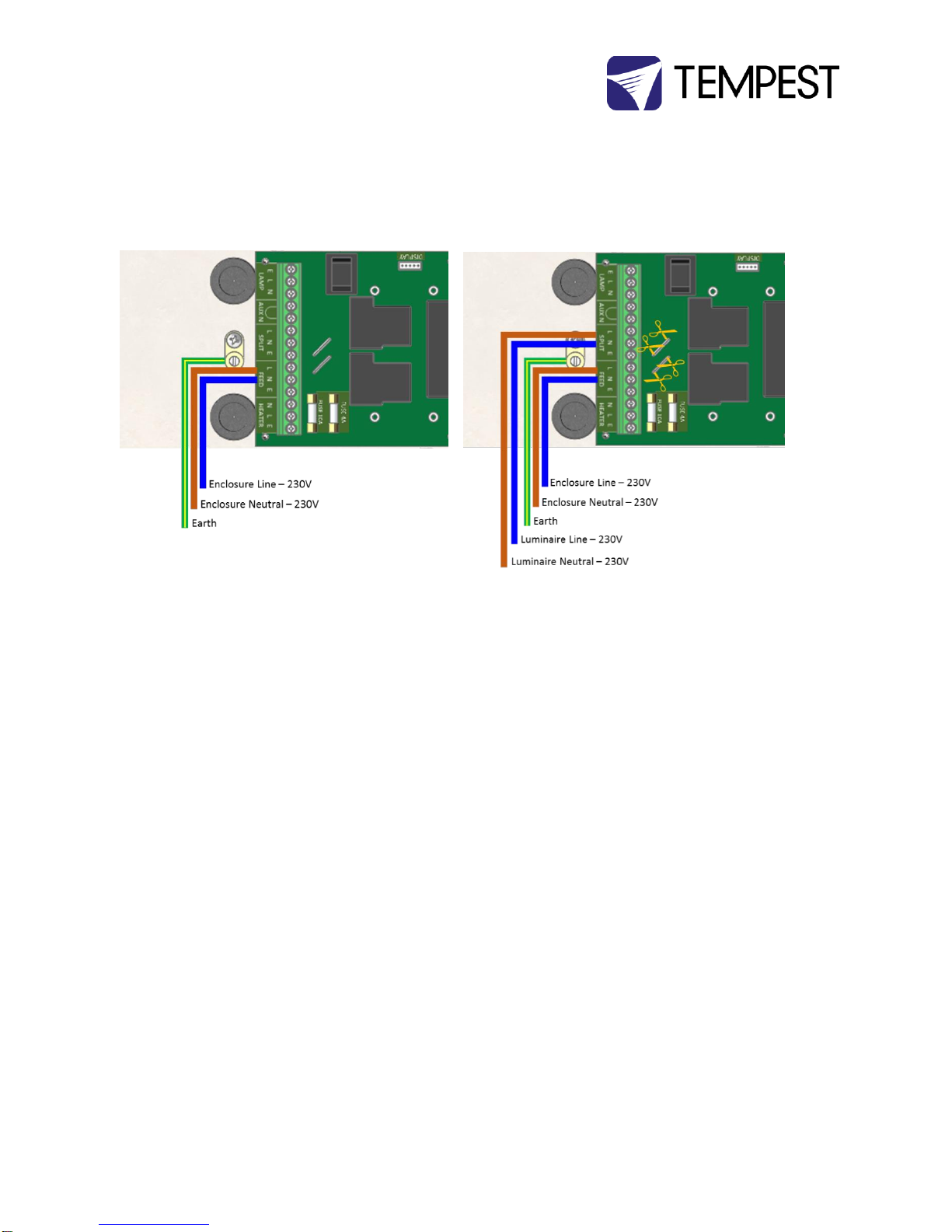
Wiring –International 220-250VAC
Note: For clarity, internal wiring is not shown.
Single Feed
Split Feed

Tornado G4 User Manual 19
Remote Monitoring Connections
Tempest G4 enclosures optionally support four types of
remote monitoring:
1. Direct via Ethernet, using Tempest TEMP
protocol (see Appendix –TEMP Protocol)
Requires 51.EN Ethernet board
2. Grouped via RS485, using an Ethernet bridge and
Tempest TEMP protocol (see Appendix –TEMP
Protocol)
Requires one 51.485 RS485 board per enclosure
and one 51.EN Ethernet board per bridge
3. Grouped via RS485, using DMX/RDM –see next
page
Requires one 51.485 RS485 board per enclosure,
and one JESE RDM-TRI Interface

Tornado G4 User Manual 20
Direct Ethernet Monitoring Network
See Appendix for TEMP protocol programming information.
Table of contents


