TempMaster LS-1628 User manual

Quick Start Guide for Equipment Touch and
LS-1628 Unit Controller, Standard 3.1.5 Program
Introduction
This start-up guide will guide you through the
necessary procedures to start-up the unit equipped
with an LS-1628 controller. Before turning on the
controller, be sure all wiring is completed and in
the proper location. All input connections (i.e. SAT
sensor) wire into the grey terminals located on the
bottom of the controller. All output connections
wire into the blue terminals located on top of the
controller. Refer to the wiring diagram included with
the unit for the connections specific to this unit.
If installing a zone or room sensor, wire to TB5
terminal blocks, these will be factory wired to the
controller’s Rnet port located on bottom-left of the
controller. Refer to the wiring diagram included with
the unit for the connections specific to this unit.
Figure 1: LS-1628 controller
Form Number: TPM54-SU2 (321) New Release
Issue Date: 2021-03-16

Figure 2: Equipment touch
The equipment touch will be prewired by the factory
and mounted to the electric panel.
The equipment touch 2 (EQ2) is powered by 24
VDC, a DC power supply is provided and wired
into the grey connector shown in Figure 2. The
green and white wires run to TB 5 Rnet + and Rnet -
connections.
Note: DO NOT CONNECT old equipment touch
(EQ1) or ET1 Kits to this connection, it could
damage the controller, EQ1 or ET1 tablet.
The controller can now be turned on by the switch
on the upper left-hand side of the controller.
Once turned on, the controller will go through
a built-in start-up diagnostic, which can take
approximately 10 seconds to complete. After this,
the sensors and controls will become fully available
and the EQ2 display will upload and configure the
display to show the Home screen.
Note: This takes about 5 minutes to complete.
If nothing is touched or pushed on the Home
screen for 5 minutes, the Standby screen will
appear as below.
Note: The EQ2 screen timeout is set to a
standard setting of 2 minutes, this can be
adjusted, see .
Figure 3: Start-up diagnostic
The Standby screen shows the program name,
version number, date of revision issue, and the
current operational condition/mode of the unit (i.e.
UNOCCUPIED/SCHEDULE is the initial condition).
Press the continue button on the keypad to go to
the Home screen.
Figure 4: Standy screen
Equipment touch notes
First thing to note is the new EQ2 operates just like
a tablet or smart phone, the screen has a timeout
setting (the standard setting is 2 minutes, but is
adjustable to 10 minutes), when not used for the
allotted time the screen will timeout and turn off,
to wake screen simply touch anywhere on screen.
This is a Touch screen device so you will touch the
objects for the links, changing parameters, and
even to scroll by use of the slide bars on the right or
bottom of the screen.
Note: When scrolling and touching the screen
the new EQ2 has a ZOOM function that will
activate if the screen is touched three (3) times
in rapid succession, to return to normal view,
tap 3 times again in rapid succession. All menu
items can be accessed by slide bar, holding an
arrow, or placing your finger on the slide and
moving it. If a line is too long a slide bar will
appear on the bottom of the screen.
Quick Start Guide for Equipment Touch and LS-1628 Unit Controller, Standard 3.1.5 Program2

Password enter screen
There are 3 levels of passwords used in the
program, User, Admin and Factory passwords. User
passwords are not used often as most of those
screens are for READ OUT sensors and unit data.
Most changes will require an ADMIN PASSWORD
because these are specific configuration and are not
meant to be changed unless authorization has been
given. Once an ADMIN password has been entered
ALL screens and buttons below that level will not
need a password to be re-entered unless it requires
a Factory password. Factory password protected
changes that must be performed by an authorize
service tech, please contact the manufacturer's
technical service representative if assistance is
required. The password will timeout after 5 min of
screen inactivity and need to be reentered, when
this happens you will be brought back to the Unit
Status screen.
Note: You will need to switch the keyboard
input to numbers to enter the password.
Figure 5: Enter password
Table 1: Reference table for main screens.
Navigation
button Description Password Reference
Unit status Main settings and modification screen None
Tech settings Occupancy control, SF min setting, enable settings Admin
Misc. setup BAS, ModStat, config Admin
Calibration Allows manual +/- of sensor readings – used for testing of unit and sensor
calibration Admin
Unit config Shows unit information, serial number, operational configuration, factory
options Admin
Setpoints/DB Adjustment to “adjustable” setpoints.
Note: Some setpoints/DBs are not adjustable from factory Admin
Settings, controls, and options
Procedures for setting up the date and time,
schedule of occupancy, modifying parameters of
operation, and selectable options, such as adding
zone sensor and safety switches. For specific
operational information for this unit, refer to
the unit specific Sequence of Operations provided
separately.
The controller will be pre-configured from the
factory with the necessary options for the unit to
operate properly. However, some items may need
to be modified in the field as required. This can be
achieved in the field through the EQ2 display.
Unit status screen
From the Unit status screen, most of the status
screens can be accessed. Also, the alarm reset will
appear on the home screen if the controller is in an
alarm state. Once alarm is reset, the Reset Alarm
text will hide itself.
Quick Start Guide for Equipment Touch and LS-1628 Unit Controller, Standard 3.1.5 Program 3

Figure 6: Unit status screen
All screens will have the top two lines which includes
a home, previous, and an alarm link. These links
on the Unit Status screen are followed by the date
and time. The next line will have the operational
condition/mode of the unit. This screen will have
links depending on the options of the unit, such
as ECW (Energy Wheel), Econ (Economizer), EF
Fan (Exhaust Fan), HP1 and HP2 (Heat Pump)
not shown, see Sequence of Operation for specific
configuration. Below are two status screens.
You can use this screens to test your Sequence
of Operation on the unit. The Supply fan status
screen shows the supply fan (SF) status is turned
On and the UO9 light will be On. The SF_APS is the
feedback from the Air Proven Switch or a current
sensor. The SF MOD is the percentage output of
the VFD. Minimum is the lowest speed the SF can
run (default is 50% or 30 Hz.). The second screen is
for Cooling 1 status. On the left side of the screen
are different status points. C1 EN will light when
the ZAT is 1°F above the Clg1 EN SP. Y1 will light
when the compressor 1 command or UO10 is turned
On. CMP1 will light when the current sensor closes
for compressor 1. HPS1 and LPS1 should always
have the light on. FRZ1 will light when the DXLAT1
sensor is below 38°F. Clg Mode will be on, when
OAT is above 55°F and there is demand for cooling
or dehumidification. Min off and on are 5 minute
timers. When the compressor starts or stops it
must remain or be off for 5 minutes. They will start
at 5 minutes and count down. These timers meet
Copelands requirement of 6 starts an hour. There
are two of the status screens for this unit. The
rest of the status screen are similar by using the
Sequence of Operation, then you can check the status
of unit.
Figure 7: Unit status screen 1
Figure 8: Unit status screen 2
Tech settings screen
The Tech Settings screen can be accessed by
selecting the Setup link from the Unit Status
screen. The Tech Settings screen includes
navigating links for Unit Config screen, Tech
Setup screen, Schedule screen, Calibration
screen, etc. Here is where you will be able to add
and/or calibrate sensors and access screens for
occupancy control and settings. Just like the Unit
Status screen, the Tech Settings screen will have
additional links such as DPT, AMS, Reset (ZAT/SAT),
based on unit configuration.
Quick Start Guide for Equipment Touch and LS-1628 Unit Controller, Standard 3.1.5 Program4
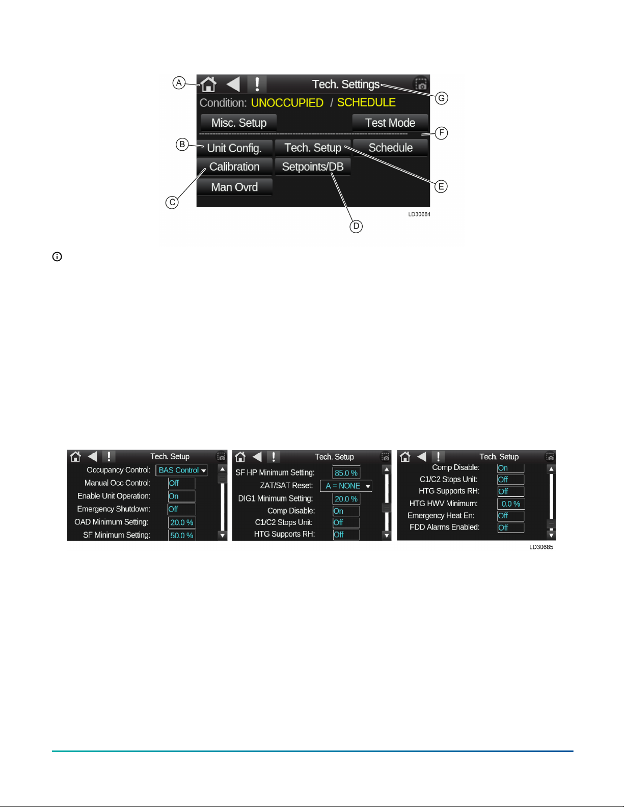
Figure 9: Tech settings screen
Note:
• A: Back to Unit status screen.
• B: Shows model and program version,
optical sensor enable options.
• C: Allows calibration of all installed sensors
for temp and humidity.
• D: Allows manual inputs of adjustable
setpoints and deadbands.
• E: Occupancy control, shut down settings,
supports.
• F: Schedule is used to setup an internal
schedule on the controller.
• G: Screen title.
Tech setup screen
Tech setup allows for unit override controls and
certain operational parameters. Parameters that
can adjust/changed in tech setup are occupancy
control, unit enable supply fan minimum run
settings, ZAT/SAT reset on/off, emergency heat
enable and many more.
Please refer to specific unit sequence of operation
for specific run conditions and set points.
Figure 10: Tech setup screen
Unit configuration screen
To access the Unit configuration screen, select
the Unit Config link on the Tech Settings screen.
The Unit configuration screen you can select
options for miscellaneous controls that are FACTORY
options. This screen also displays the factory S/
N and unit configuration, zone sensor set up
(optional), night set back options can be enabled
and miscellaneous options A and B (COS, SD, CFI).
Quick Start Guide for Equipment Touch and LS-1628 Unit Controller, Standard 3.1.5 Program 5

Figure 11: Unit configuration screen
Note:
• A: Unit configuration by factory selected
options.
• B: Factory serial number (unit serial
number).
• C: Optional, can add a zone sensor if
needed.
The following four charts show all avaibable options
for the four selectable drop-down menus. These
options can be added to the unit or may have come
from the factory.
Figure 12: ZAT sensor options
Figure 13: Option A
Figure 14: Option B
Quick Start Guide for Equipment Touch and LS-1628 Unit Controller, Standard 3.1.5 Program6
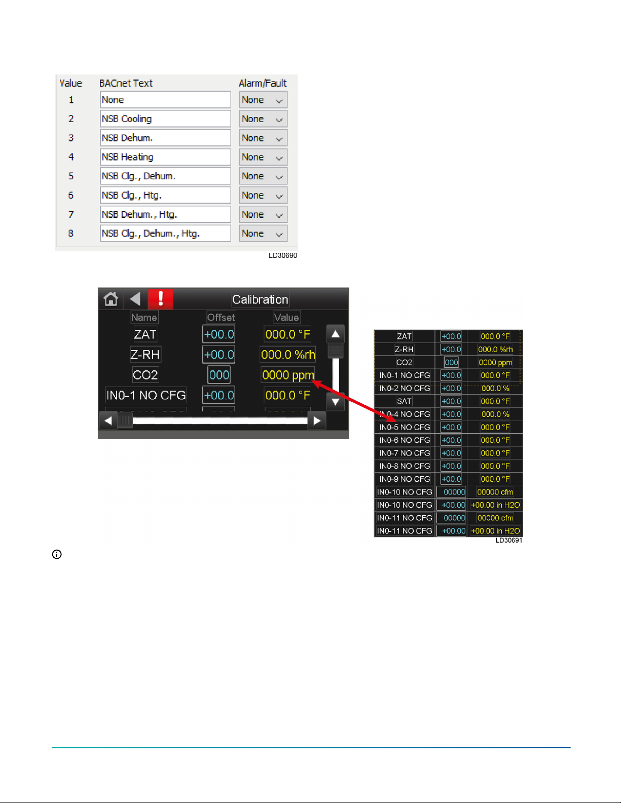
Figure 15: NSB options Calibration screen: control sensor
readouts and manual adjustments
Use the Calibration screen to see all sensor values
and to apply an offset. The value shown represents
the current value + the offset given. This screen is
used for testing purposes to enable an operational
state or to calibrate a sensor reading.
Figure 16: Calibration screen
Note: The Calibration screen displays the
current value + offset. If the offset is zero, the
value is current sensor reading.
Quick Start Guide for Equipment Touch and LS-1628 Unit Controller, Standard 3.1.5 Program 7
Setpoint and deadband screen
The Setpoints/DB screen allows you to adjust any
setpoints that need to be adjusted through field
test and balancing. These setpoint come preset to
a factory setting during the initial program unless
requested otherwise. Admin password is required to
access and change any setpoints.
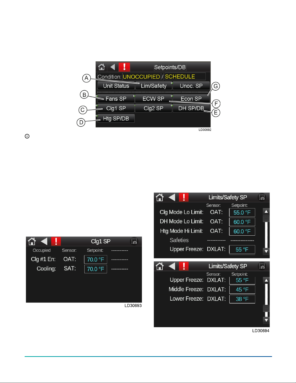
Figure 17: Setpoint and deadband screen
Note:
• A: Limits and safeties
• B: Supply and exhaust fans setpoints and
deadbands
• C: Cooling setpoints (Clg1 SP and Clg2 SP)
• D: Heating setpoint and deadband
• E: Dehumidification setpoint and
deadband
• F: Energy wheel setpoint and deadband
• G: Economizer setpoint
See for an example of the setpoint screens available
from the Setpoints/DB screen.
Figure 18: Cooling 1 setpoint
These setpoints are all adjustable, the sensor is NOT
adjustable and is for information only.
Limits and safety setpoints
The Limits/Safety SP screen allows you to see the
lower and upper limits of the deadbands. These
deadbands are editable and the standard values are
set from the factory. An admin password is required
to access the Limits/Safety SP screen.
The sensor tag is not adjustable and for information
purposes only. The sensors are set from factory and
can only be changed or modified when instructed
to do so by technical service. If you have any
questions, please call technical service.
Figure 19: Limits and safety setpoints
Quick Start Guide for Equipment Touch and LS-1628 Unit Controller, Standard 3.1.5 Program8

Default limits: all values are degrees Fahrenheit
• Cooling mode Lo Limit: 40° to 65°
• Dehumidification mode Lo Limit: 55° to 90°
• Heating mode Upper Limit: 40° to 70°
• Compressor disable OAT: 0° to 50°
• Upper freeze protection: 28° to 55°
• Middle freeze protection: 28° to 55°
• Lower freeze protection: 28° to 55°
• ECW defrost WExAT: 0° to 20,000°
Occupancy control
Press the Occupancy Control drop down menu
option, the Occupancy Control parameter dictates
where the unit control for occupied mode of the unit
originates, all modes can be set in the field and/or
overridden by the BAS.
Figure 20: Occupancy control
•Local schedule – internal schedule on the
controller.
•BAS control – building automated system
controls unit enable by writing to manual occ
control point, occ enable.
•24/7 operation – runs continuously, unit does
not have an unoccupied mode unless the
occupancy enable is changed.
•S/S switch – on/off signal control, could be a
switch or a digital input (DI) (UI12, option A
selected in ET2)
•CO2 occupancy – CO2 sensor enabled control.
When the CO2 level reaches 300 ppm, the unit
will be placed in occupied mode.
Note: This will require a CO2 zone (space)
sensor for reading space CO2 and enabled
in Config screen on ET2.
Setting a schedule
There is no default schedule for the LOCAL SCH option. Change the schedule to the desired hours. To edit
the schedule, select the Schedule button on the Setup Status screen.
1. Click the Add Schedule button in upper right corner.
2. Enter a name for the schedule – example here is named Addison Schedule.
Quick Start Guide for Equipment Touch and LS-1628 Unit Controller, Standard 3.1.5 Program 9

3. Select schedule type – you can choose On schedule - occupied or Off schedule - Unoccupied.
4. Select time and date – we recommend weekly schedules. Leave the Date Range to NO. Make sure to set
the time to the hours for occupied schedule unless otherwise stated by customer.
5. Click Save Schedule button on bottom of screen. Then press OK button.
Quick Start Guide for Equipment Touch and LS-1628 Unit Controller, Standard 3.1.5 Program10

6. Confirm schedule is correctly input and saved
by verifying the monthly screen. There are
green bars in all days where schedule is active.
For example, in the following figures, the
schedule is set for Monday through Friday
every week. By clicking the drop-down option
where the word Monthly is shown, you can see
the schedule in weekly view or daily.
Misc status screen
The Misc Setup screen can be accessed by selecting
the Misc Setup link from the Unit Status” screen.
The “Misc Setup” screen includes navigating
buttons for “BAS setup” and “Modstat.” The “BAS
setup” button allow you to set up communication
with BAS as well as network device information.
“Archive” will allow for backup and restore functions
of the installed unit specific program.
Figure 21: Misc status screen
Quick Start Guide for Equipment Touch and LS-1628 Unit Controller, Standard 3.1.5 Program 11

Config status screen
This screen will show you the unit type, the Model
number, the Serial number of the unit and the
program code string and version number. This
screen also has buttons for Sensors and Options,
both allow for modification of controlling and field
installed sensors options including ZAT/RH sensor,
condensate overflow, clogged filter and smoke
detector.
Figure 22: Config status screen
Changing settings
Note: The last value or command will set the
point. When a BAS system is connected to the
unit, the BAS may continually write to the point.
If you change a value or condition the BAS may
overwrite your command. Disconnecting the
BAS input wire will generate a BAS comm lost
alarm and change the OAT/OARH reading to
the unit supplied sensor.
All settings can be changed using the following
method.
1. Press the button for the desired screen.
Note: Some screens will require a USER/
ADMIN password to access. Please contact
your local Johnson Controls service
branch.
2. Enter the password and press the Log in
button.
Note: You will need to switch the keyboard
input to numbers to enter the password.
3. Change the state of a two-position point or
multi-stat point by pressing the desired button.
A drop-down menu will give you your choices.
4. Press the button of your desired choice. The
select choice will appear on your button. You
may need to scroll by using the slide bar.
5. For a value press on the value, a second
window will open, press on the value and a
keypad will appear.
6. Now enter the desired value and press the OK
button.
Figure 23: Change password
Settings
The program will default to the factory download
or last archive. Start on the home screen, press the
SETUP button. Press the Controls button and you
will be prompted to enter an admin password. Then
the following screen will appear with the default
values. The first line has Occupancy Control set
for the default setting BAS CONTROL. You can use
the second line to place the unit into unoccupied/
occupied mode. The Lock OAT/OARH Sensor ON:
is set for the default of Off. The default values are
OAT of 60°F and OARH of 50%. These two read/
writable points will be updated by the BAS with a
local temperature and humidity readings. These
neutral temp and humidity will give time to check
the damper and supply fan control, see Sequence
of Operations. Testing of the unit can be achieved
by using the calibrate screen and adjusting your
temperature or humidity values.
Quick Start Guide for Equipment Touch and LS-1628 Unit Controller, Standard 3.1.5 Program12
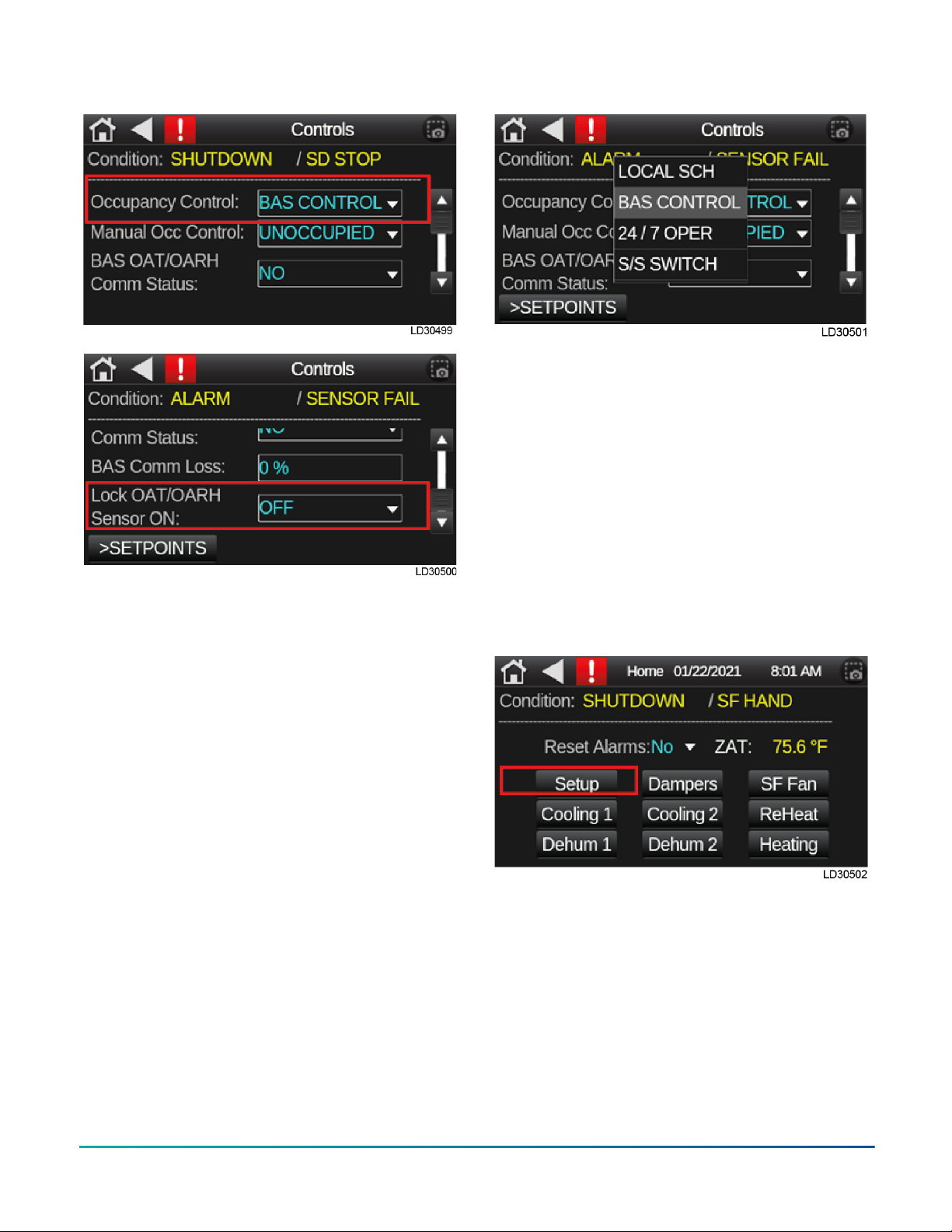
Figure 24: Settings
Occupancy control
Press the Occupancy Control drop down menu
option, The Occupancy Control parameter dictates
where the control of the Occupied Mode of the unit
originates, all modes can be set in the field and/
or overridden by the BAS. The occupancy control
options are below:
1. LOCAL SCH: Select if the Controllers schedule is
to be used.
2. BAS CONTROL: Select if the BAS is used for unit
control and enable.
3. 24 / 7 Operation: Select if unit will run in 24/7
Occupied Mode.
4. S/S Switch: Select if occupancy control is from a
separate unit controller binary input (UI-12).
5. CO2 Control: Select if occupancy control is
based upon CO2 levels.
6. Clock Ovrd: Select to override scheduled
unoccupied condition and place unit in
occupied mode for a set period of time
(adjustable; 30 minutes default).
7. Manual Ovrd: Select to manually force
Occupied or Unoccupied Mode.
Figure 25: Occupancy control
Settings before startup
From the Home screen, select the Setup button,
then select the Setpoints/DB button to pull up
the setpoints screen. From the Setpoints/DB
screen you can access fan, cooling, heating and
dehumidification set points. Also, the limits and
safeties are accessible thru the Setpoints/DB
screen.
One thing that should be done before startup
begins is select the Fan SP (default is 3900) and set
the SFAMS Air Flow set point to the desired CFM.
For a value press on the value, a second window will
open, press on the value and a keypad will appear.
Now enter the desired value and press the OK
button.
Quick Start Guide for Equipment Touch and LS-1628 Unit Controller, Standard 3.1.5 Program 13

Start-up
Let's get started on the startup of the unit. The best
way to check the unit out is to follow the Sequence of
Operations.
1. All sensor readings should display a good
value. A sensor reading -60.2 or 296 has an
open circuit or is shorted respectively. The
condition on the second line will display
“ALARM/ SENSOR FAIL” or “SAT FAIL’. By
selecting the alarm key (red square with
an exclamation point on top line) the new
screen will display the failed sensor. If there
are no failures navigate to the Calibration
screen by press the Setup link on the Home
screen. Now press the calibration link to
display the Calibration screen. Show all
points. Remember the unit will receive the
OAT/OARH readings from the BAS system.
However, you should check the local OAT/OARH
sensor by navigating to the Control screen
and turning on “Lock OAT/OARH sensor ON”.
Return to the Calibrate screen and check the
OAT/OARH reading. Turn this option off after
verifying the readings. Correct the sensor
before proceeding. The SF AMS reading will be
checked after the supply fan is running.
Quick Start Guide for Equipment Touch and LS-1628 Unit Controller, Standard 3.1.5 Program14

2. Place the unit in the occupied mode. From the
Home screen select Setup button, the select
the Controls button to navigate to the controls
screen. Change the MANUAL OCC. CONTROL to
OCCUPIED. Since the Occupancy Control is set
to BAS CONTROL, you can check the damper
and supply fan operation. The Damper and
Fans screen will show their status.
3. Damper status: From the Home screen press
the damper link. On the screen you will see
OA DAMPER twice, the first is the command to
open the damper and UO14 on the controller
will light up. The second OA damper is a
feedback from the actuator that the damper
has opened xx%. The Smoke detector status
will display normal/alarm. If the status is
showing an alarm, then the condition line will
display SHUTDOWN/SD STOP. Once the smoke
detector is restored, the unit will restart.
4. Fan screen: The SF Status is the command to
start the fan, then the status shows started
or on the UO09 on the controller will light up.
The SF-APS will show “on” when the air proven
switch or the current sensor contact closes. The
next three points are for the modulation of the
supply fan speed. The supply fan will modulate
to maintain the setpoint (Default is 3900 cfm).
The SF setpoint may need to be adjusted (check
with your TAB contractor). In some cases,
the unit is set to run as a constant air volume
(CAV). Check with the TAB contractor for the
desired percentage. To set the unit for CAV
press the setup link on the home screen. Press
the Man Ovrd link for the manual override
screen. Set the percentage to the required
value and turn the output to on. The last
status is the 2-minute countdown timer on SF
shutdown (see Sequence of Operations).
5. Cooling 1 status: The next step in the sequence
of operations will be to start compressor #1.
Go to your Calibration screen and add 12°F
to the OAT. The SOO states the compressor
will start when the OAT is 1°F above the OAT
cooling setpoint of 70°F. The CLG #1 will turn
to on when this condition is true. If the Y1 does
not turn to “on” check the Min OFF countdown
timer. If the timer is zero, the HPS1 and LPS1
status are both on, then Y1 will turn on and
UO10 on the controller will light up. Comp #1
is the feedback for the compressor #1 using a
current sensor.
Quick Start Guide for Equipment Touch and LS-1628 Unit Controller, Standard 3.1.5 Program 15

The next three points are for the modulation of
compressor #1. The compressor will modulate
to maintain the DXLAT SP (Default is 55°F).
Note: If the units for the C1 MOD shows 35 to
60 Hz, then the unit has a Bitzer compressor.
A Copeland Digital Compressor will display
the units as 0-100%. The next line will give
you the status of the purge cycle and when
the next purge will happen. The purge will
be on startup of the compressor and every
hour. During the purge cycle the condition
line will show OCCUPIED/PURGE#1. The next
two lines will display the freeze protection
status and the min off and min on timers. The
freeze protection has the DXLAT reading and
C1 FRZ status (see Sequence of Operations). The
min OFF and min ON 5-minutes countdown
timer are triggered by the compressor’s
current sensor. These timers can restrict the
compressor from shutting down or starting. If
you think the compressor should be starting
or stopping check these timers. The last line
shows the status for the 10 minute countdown
timer for the heating mode change over to
cooling mode. On the very bottom of the
screen are links to other screens.
6. Reheat (HGRH) screen: The reheat displays
that reheat is included in the unit. When RH
status is on then UO12 will light. The next three
points are for the modulation of reheat. The
modulating reheat will modulate to maintain
the SAT SP (default is 70°F).
7. Cooling 2 status: The first line has qualifiers
for compressor #2 to start (see Sequence of
Operations). Demand SP is set to 95% or 59Hz,
the 10 minute countdown timer, and the SAT
cooling setpoint plus 3°F must all be satisfied to
turn on compressor #2. Go to your Calibration
screen and add enough to the offset so the SAT
above 73°F. The sequence of operation states
that the compressor will start when the SAT
is 3°F above the SAT cooling setpoint of 70°F.
The CLG #2 will turn to on when this condition
is true. If the Y2 does not turn to on check the
min OFF countdown timer. If the timer is zero,
the HPS2 and LPS2 status are both on, then
Y2 will turn on and UO11 on the controller will
light up.
Quick Start Guide for Equipment Touch and LS-1628 Unit Controller, Standard 3.1.5 Program16

Comp #2 is the feedback for the compressor
#2 using a current sensor. The next line will
give you the status of the purge cycle and when
the next purge will happen. The purge will
be on startup of the compressor and every
hour. During the purge cycle the condition line
will show OCCUPIED/PURGE#2. The next two
lines will display the freeze protection status
and the min off and min on timers. The freeze
protection has the DXLAT reading and C2 FRZ
status (see SOO). The min OFF and min ON 5
minutes countdown timer are triggered by the
compressor’s current sensor. These timers can
restrict the compressor from shutting down or
starting. If you think the compressor should
be starting or stopping check these timers. On
the very bottom of the screen are links to other
screens
8. Dehumidification #1 screen: The first line has
the status of the OAT and the dehum lower
limit setpoint (see SOO). The OAT must be
above the lower limit setpoint and the OADP
must be above the SADP setpoint of 51°F to
enable dehum #1. When Dehum1 shows on,
then the condition line will display OCCUPIED/
DEHUM.
On the second line you have the status of the
sub-cooling coil (see Sequence of Operations).
Sub-cooling will turn on anytime we are in the
dehum mode and a compressor is running.
When the unit is running in the dehum mode
the compressor will modulate to maintain the
SADP SP of 51°F. On the very bottom of the
screen are links to other screens.
9. Dehumidification #2 screen: The SADP must be
2°above the SADP setpoint of 51°F to enable
dehum #2. When Dehum2 shows “on”. On the
very bottom of the screen are links to other
screens.
Quick Start Guide for Equipment Touch and LS-1628 Unit Controller, Standard 3.1.5 Program 17

10. Heating Screen: The next step in the SOO will
be to start heating. Go to your Calibration
screen and subtract enough temperature to
the OAT to be below 54. You may need to wait
for the heating mode to turn on. The cooling
to heating switchover is a 10 minute timer. The
OAT must be below the high limit setpoint, the
OAT must be below the OAT heating setpoint
of 54°F to enable heating. When HTG shows on,
then the condition line will display OCCUPIED/
HEATING. The next three points are for the
modulation of heater. The heater will modulate
to maintain the SAT SP (default is 70°F). The
last line shows the status for the 10 minute
countdown timer for the cooling mode change
over to heating mode. On the very bottom of
the screen the type of heat is displayed.
You have completed the startup of the 100%
Outside Air unit. Before you leave make sure
all offsets you made in the Calibration screen
are set to zero. The LS1628u does not require an
Archive to save change made in the field. The
Archive is down automatically.
BAS and communicaton specific
screens
Module status screen: network
information and device data
Module Status will allow you to get all the network
and system information for the controller. This
screen will help with trouble shooting any network
issues, show all shut down time stamps and any
system controller errors. On the new EQ2 does an
ALL-IN-ONE report when selected.
Quick Start Guide for Equipment Touch and LS-1628 Unit Controller, Standard 3.1.5 Program18

Figure 26: Module status screen
BACnet device
From the Home screen, press the Setup button,
then press the Misc. Status button to get to the
Misc. Status screen. Press the BAS Setup button to
enter the BAS Setup screen. Select Communication
menu option, this will open the communication
screen and allow you to enter BAS information.
The BACnet Device Instance being utilized in the
field will be unique for each unit. The Autogenerate
Device ID should be set to no. The rotary switch
on the controller, located in the upper left corner,
need to be set to the proper protocol (1=MSTP,
2=ARCnet) contact the FMOC for correct BACnet
Device Instance number and protocol. The BACnet
Device instance could already be populated always
check to verify correct number.
Network router and IP screens
The router and IP network number can be checked
and manually changed by using the related menus.
To access the Router screen, select Router on the
BAS screen. To access the IP screen select IP on the
BAS screen.
Quick Start Guide for Equipment Touch and LS-1628 Unit Controller, Standard 3.1.5 Program 19

The rotary switch on the controller, located in the
upper left corner, needs to be set to the proper
protocol (1=MSTP, 2=ARCnet, 3=Modbus). Contact
your BMS engineer for information of which
protocol is being used.
1. On the Router screen make sure to change
PORT S1 value to specific network number for
communication protocol.
2. On the IP screen make sure to set the IP
Network to 0 if not already.
Safety switches
•High pressure switch (HPS1): If HPS1 is open,
compressor #1 will turn off and the controller
will issue an alarm. After manually resetting
HPS1, the HPS1 alarm will reset. Following
a minimum time off delay, compressor #1
will turn on. If the controller records 3 high
pressure start/restart failure incidents within
1 hour, compressor #1 is locked out and the
controller will issue an alarm. The compressor
lock-out can be reset in the EQ2 display pad or
by cycling the power of the controller. Refer to
the IOM for more information.
• For systems with two circuits, this is the same
for compressor #2, Y2 and HPS2.
•Low pressure switch (LPS1): If LPS1 is open
after the LPS1 by-pass time, the controller
will issue an alarm and compressor #1 turns
off. After 30 seconds (fixed), the LPS1 alarm
will reset. Following the minimum time-off
delay, the compressor #1 will turn on. If the
controller records 3 low pressure start/restart
failure incidents within 1 hour, compressor #1
is locked out and the controller will issue an
alarm. The compressor lock-out can be reset
in the EQ2 display pad or by cycling the power
of the controller. Refer to the IOM for more
information.
• For systems with two circuits, this is the same
for compressor #2, Y2 and LPS2.
Safety shutdowns
•Smoke detector (optional): When a smoke
detector (SD) is provided, it is wired directly
to the controller. If smoke is detected, the
controller will shut down the unit. The alarm
can be reset in the EQ2 display pad or by
cycling the power of the controller.
• If a compressor fails to start 3 times in an
hour due to high pressure switch lock out. The
alarm can be reset in the EQ2 display pad or by
cycling the power of the controller.
• If a compressor fails to start 3 times in an
hour due to low pressure switch lock out. The
alarm can be reset in the EQ2 display pad or by
cycling the power of the controller.
• If a compressor fails to start 3 times in an hour
due to DX LAT or suction line temperature lock
out. The alarm can be reset in the EQ2 display
pad or by cycling the power of the controller.
If the controller detects an SAT sensor failure. The
alarm can be reset in the EQ2 display pad or by
cycling the power of the controller.
TEMPMASTER® IS A REGISTERED TRADEMARK OF JOHNSON CONTROLS © 2021 Johnson Controls. All rights reserved. Subject to change
without notice. 100 JCI Way, York, Pennsylvania USA 17406-8469.
Table of contents


