6 7
Electric shock hazard:
Contact with live circuits could result in severe injury
or death.
Electric shock hazard:
• Do not change the measurement function while the test leads are connected to a
component or circuit.
• Do not use the meter to measure voltages in circuits that could be damaged by the Auto
V•Ω mode’s low input impedance (approximately 160 kΩ).
Failure to observe these precautions may result in injury and can damage the unit.
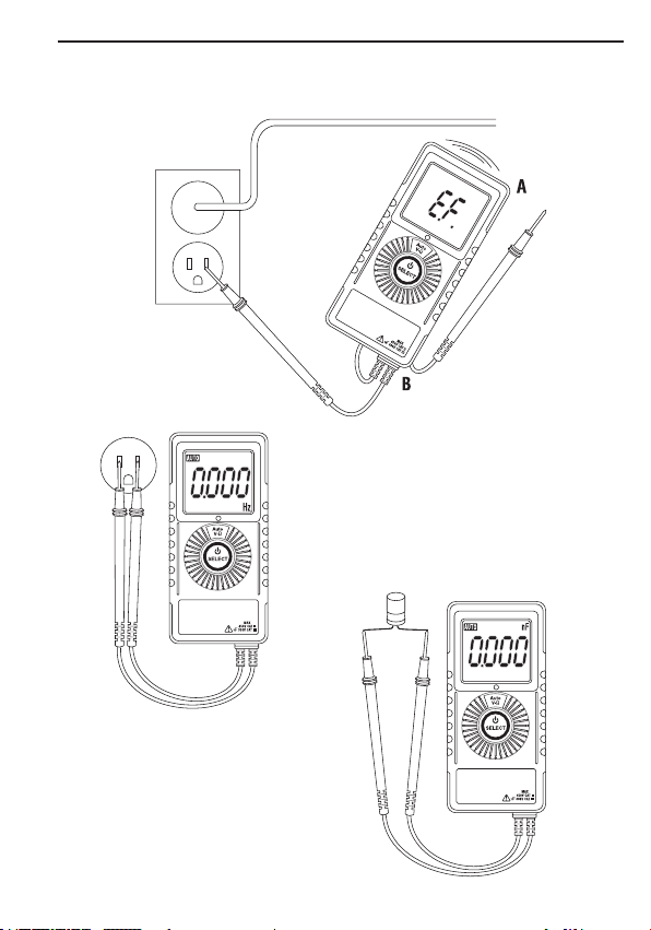
Using the Features
• Low Impedance Auto V•Ω Mode In this mode, the meter automatically selects the
proper
measurement based on the input.
– If there is no input, “Auto” appears on the display.
– If voltage above approximately 2 volts AC or DC is present, voltage is displayed.
The meter
beeps once when switching from Auto to voltage measurement.
– If both AC and DC voltages are present, the larger voltage is displayed.
– If no voltage is present and there is resistance less than 6 MΩ, resistance is
displayed.
This mode features low input impedance to mask stray or “ghost” voltage pickup. The
input impedance is approximately 160 kΩ.
Overload Alert Feature: When above rated voltage is present (450 V), the meter
displays “OL”, with a warning beep tone. Disconnect the test leads from the voltage
source immediately.
Function Lock Feature: When a measurement is being displayed in Auto V•Ω mode,
pressing the button one time will lock in that function. Pressing the button again will
return the multimeter to Auto V•Ω mode. It is sometimes useful to “lock in” a function.
This may be helpful for measuring low voltages.
•Intelligent Automatic Power Off (APO) To extend battery life, the meter shuts itself
off after approximately 3 minutes of inactivity. Inactivity occurs when the selector
button is not pressed. The meter will not enter APO when there are signicant readings
over 10% of the range or non-OL readings for resistance and continuity.
Operation