ULTRICS UT0021YB User manual

USER GUIDE
Digital
Multimeter

Safety Precautions and Procedures
This multimeter is designed according to relevant clauses of IEC1010. To avoid possible electrical
shock, fire, or personal injury, please read all safety information on this manual before you use the
product.
Do NOT exceed the "maximum value" indicated on the Panel.
Examine the connection of the test leads and the insulation of the product before
measuring a voltage higher than 36V DC or 25V AC.
Disconnect the test leads from the circuit before changing the mode.
Should check and confirm there is no damage in the instrument, the insulating barrier of
test lead is intact before using.
While holding the test leads, should pay special attention that your hands do not exceed
the plastic of the testing needle root, otherwise there is danger of getting electric shocks.
Before opening the back cover, must pull out the test leads. After closing the back cover
and screwing it back, it can carry on measuring. Be sure that it is done properly.
Before rotating the range selector to change functions, disconnect test leads from the
circuit under test.
Never input signal electronic voltage exceeding the limited value to avoid dangers and
damages.
The potential difference between the measurement public terminal COM and earth cannot
exceed 600V.
For the fuse, it must be replaced with an identical model if necessary. For the concrete
specification, please see the clause of maintenance or label on the instrument board.
If there is a symbol on the LCD display, it indicates low battery. Replace the battery to
ensure measurement accuracy.
Digital Multimeter www.ultrics.uk
01
Safety Symbols
AC voltage/current
Hazardous Voltage
Double insulation
DC voltage/current
Ground connection
Risk Of danger
Buzzer
Diode
Low battery indication

General Description and Function Panel
Specification
Digital Multimeter www.ultrics.uk
02
VΩ mA jack
LCD display
Data hold button
10A range input jack
COM jack
Back Light button
Rotary switch
Display: Max 1999 (3 1/2 digits)
1. DC Voltage
Input impedence: 1MΩ
Automatic polarity display, range instruction and battery changing indicator.
Power supply: 9V battery (NEDA 1604; 6F22 type or equivalent type)
Environment condition:
Working temperature: 0° C- 40° C; The relative humidity: <85 %
Store temperature: -10° C - 50° C; The relative humidity: <85 %
Temperature of precision: 23° C+5 C°; The relative humidity: <75 %
Range
200mV
2V
20V
200V
600V
Accuracy
(0.5%+2)
+
-
(0.8%+2)
+
-
Resolution
100uV
1mV
10mV
100mV
1V

Specification
Digital Multimeter www.ultrics.uk
04
2. DC Current
10A range does not guarantee fuse protection, 10s at most.
Input impedance: 450k Ω
Frequency range: 40HZ-400HZ
Overload protection: peak value 600V for AC virtual value
Reveal: Average (the average of the virtual value of sine)
5. Diode Test
Test voltage approx 2.8V, current 1.5mA
Indicate forward voltage drop of diode unit: k Ω
7. Continuity test
Test voltage approximate 2.8V, current 1.5mA
The buzzer will beep when conductance resistance approximate<30
Range
mA 1.5 V
2 mA
20 mA
200 mA
10 A
Accuracy
2
(1.2%+2)
+
-
(2.0%+2)
+
-
(1.4%+2)
+
-
Resolution
Only can test 1.5V battery current
1 uA
10 uA
100 uA
10 mA
4. Resistance
Range
200 Ω
2k Ω
20k Ω
200k Ω
2M Ω
Accuracy
(0.8%+5)
+
-
(1.0%+2)
+
-
Resolution
1 Ω
0.1 Ω
10 Ω
100 Ω
1 k Ω
6. Transistor hFE Test
Range
NPN & PNP 1b=10uA Vce=3V
Test Range Test Current Test Voltage
0-10000
3. AC Voltage
Range
200V
600V
Accuracy
(1.5%+8)
+
-
Resolution
100 mA
1 V

Operating Instructions
Digital Multimeter www.ultrics.uk
05
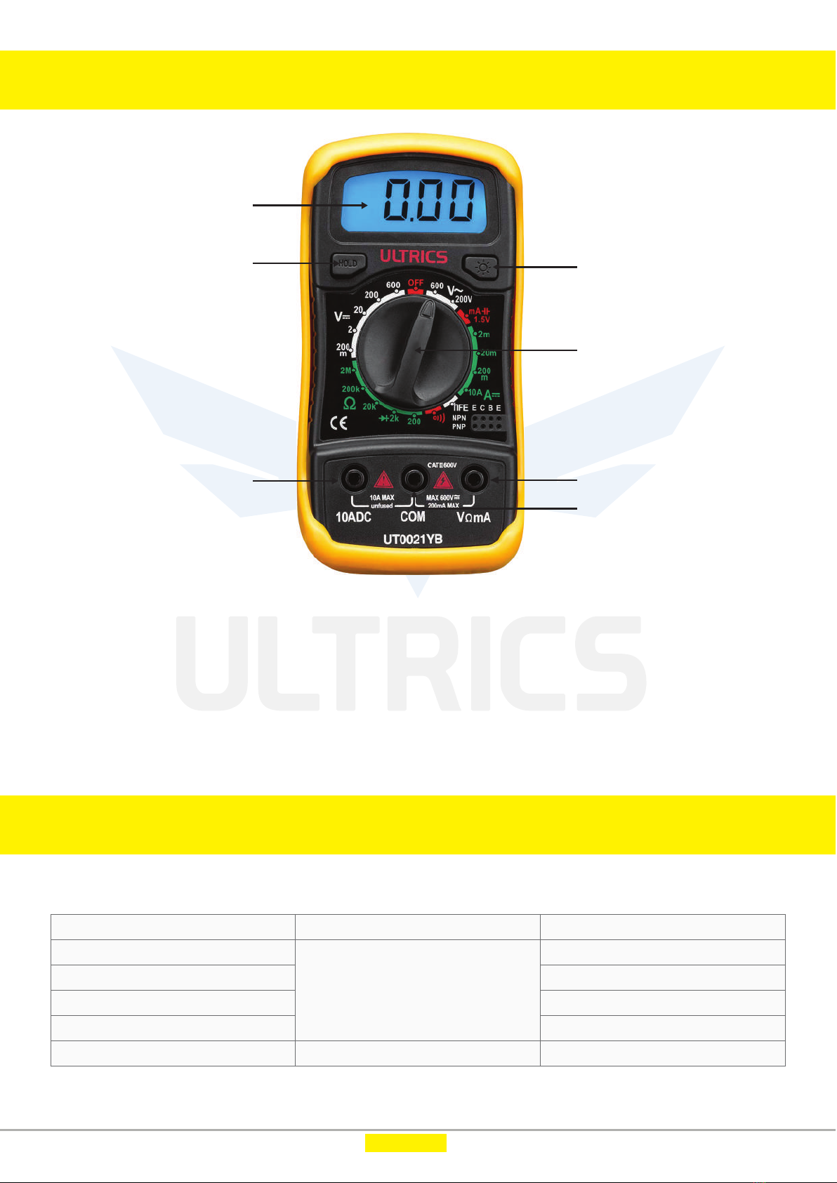
Front Panel (Please see the panel)
1. LCD display, 1999digits
2. Buttons
i. Hold: To hold the current reading, press this button and you will see "H" on the display,
press again to cancel.
ii. Display Backlight: To turn on the display light.
3. Rotary switch: To change mode or range.
4. V/Ω/mA: Input terminal for Voltage resistance, current (mA) diode, continuity measurements.
5. COM: Common Terminal for all Measurements.
6. 10A: Input terminal for related current measurements.
(1) Measure AC/ DC voltage
1. Insert the red test lead to the "VΩmA" terminal, and the black test lead to the "COM" terminal;
2. Turn the rotary switch to the DC voltage mode, or the AC voltage mode, choose the suitable
range if can't sure, choose the highest range.
3. Connect the probes to the correct test points of the circuit to measure the voltage;
4. Read the measured voltage on the display.
(2) Measure DC current
1. For current less than 200mA, insert the red test lead to the "VΩmA" terminal, if current is more
than 200mA, insert the red test lead into "10A" terminal, and the black test lead to the "COM"
terminal.
2. Turn the rotary switch to the DC current related Mode.
3. Break the circuit path to be measured. Then connect the test leads across the break and apply
power.
4. Read the measured current on the display
Caution:
a. Do not measure voltage exceeding the MAX value as indicated on the panel.
b. Do not touch the high voltage circuits during measurements.
Caution:
a. Do not measure current that exceeds the MAX value as indicated in the specifications;
b. Do not input voltage exceeds 36V DC or 25V AC when you are at the setting of measuring current.

Operating Instructions
Digital Multimeter www.ultrics.uk
06
(3) Measure Resistance
1. Insert the red test lead to the "VΩmA" terminal, and the black test lead to the "COM" terminal;
2. Turn the rotary switch to the resistance, choose the suitable range;
3. Connect the probes to the desired test points of the circuit to measure the resistance;
4. Read the measured resistance on the display.
(4) Measure Diode
1. Insert the red test lead to the "VΩmA" terminal, and the black test lead to the "COM" terminal;
2. Turn the rotary switch to
3. When test leads connect with resistance, instrument is in the ultra-range state (only reveal high
position 1);
4. Read the forward bias voltage value on the display.
Caution:
a. Disconnect circuit power and discharge all capacitors before you test resistance.
b. Do not input voltage at the resistance mode.
(5) Measure Continuity
1. Insert the red test lead to the "VΩmA" terminal, and the black test lead to the "COM" terminal;
2. Turn the rotary switch to position ;
3. Touch the probes to the desired test points of the circuit;
4. If the resistance examined between the two ends is less than 300, the instrument will send out
bee sound of chirping.
(6) Transistor Test
1. Set the rotary switch at "hFE" position;
2. Determine whether the transistor under testing is NPN or PNP, and locate the emitter, base and
collectors leads. Insert the leads into proper sockets on the panel.
3. Read the approximate hFE value at the test condition of base current 10uA and Vce 3V.
(7) Replacing the Battery
The sign displayed on the screen indicates requirement for battery replacement. Be careful to
observe battery polarity.
Caution:
a. Do not input voltage at the continuity mode.
Caution:
a. Do not input voltage at the diode mode.
b. Disconnect circuit power and discharge all capacitors before you test diode.

Accessories Included
Warning and Caution
This user manual is also available in these languages
You can download the user manual in your preferred language
from our website (ultrics.uk) in forms of eBook.
Digital Multimeter www.ultrics.uk
07
1. Multimeter
2. One pair of test leads
3. Manual
4. 9V 6F22 battery
Be cautious about the condition of the meter and the testing leads before using.
Please turn off the item when it is not in use in order to prolong its working life. Remove
the battery and put it in a dry, ventilating and less dusty place if the instrument is not used
for a long time.
Disconnect the test leads from the circuit before changing the mode.
French German Italian
Spanish SwedishPolish Dutch

We, ULTRICS provide our customers with an unparalleled experience by making
the best professional products in the world. We will definitely continue to
innovate and challenge old paradigms with new solutions.
www.weareheretohelp.co.uk
Thank you for being with us. Stay connected.
Support
Register your product in our website and get up to
18 months warranty.
To Register
www.ultrics.uk
Table of contents