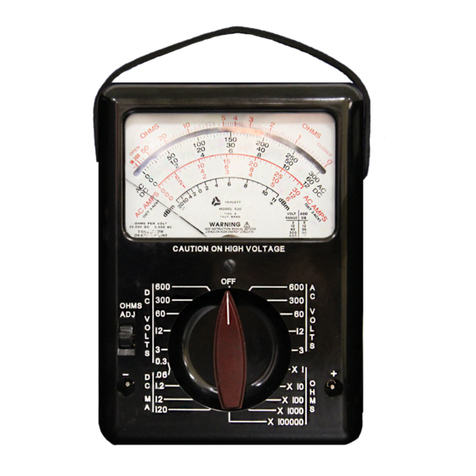
Triplett MM300 User manual
Other Triplett Multimeter manuals

Triplett
Triplett 310-TEL 4 User manual
Triplett
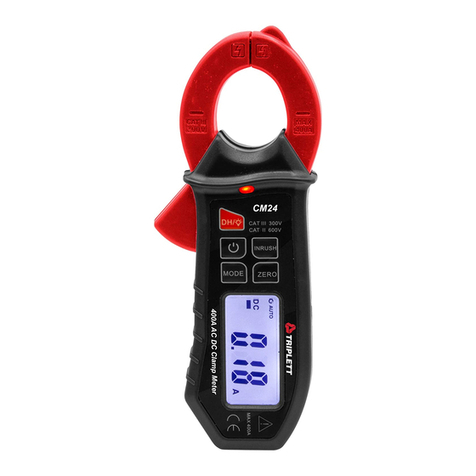
Triplett CM24 User manual
Triplett
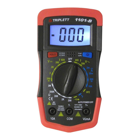
Triplett 1101-B User manual

Triplett
Triplett 1101-B User manual
Triplett
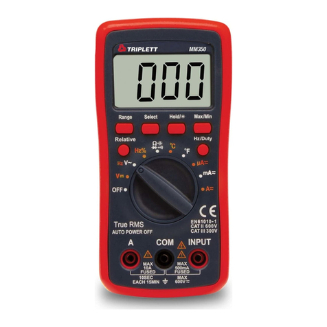
Triplett MM350 User manual
Triplett
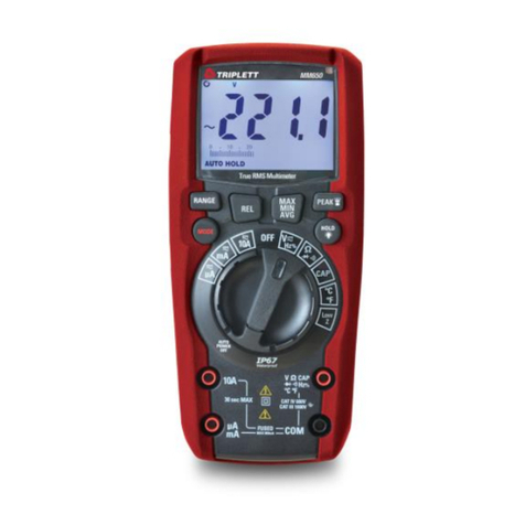
Triplett MM650 User manual

Triplett
Triplett 1201 User manual
Triplett
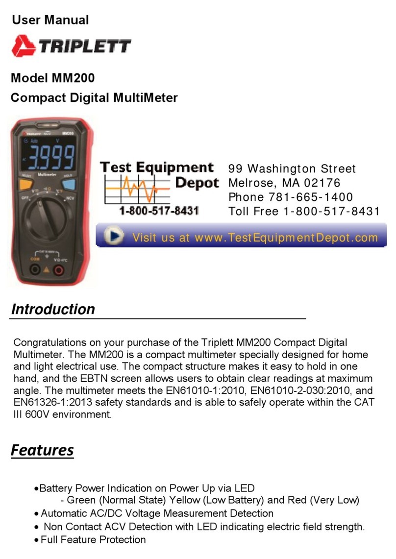
Triplett MM200-NIST User manual
Triplett
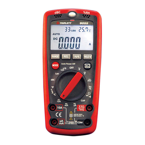
Triplett 9055 User manual
Triplett
Triplett 3303 User manual
Triplett
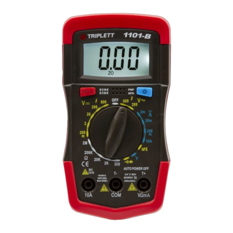
Triplett 1101-NIST User manual
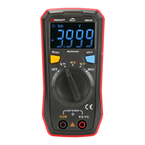
Triplett
Triplett MM200 User manual
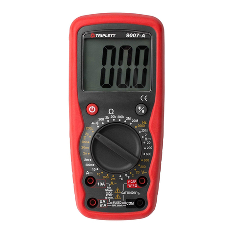
Triplett
Triplett 9007-A User manual

Triplett
Triplett 1101-B User manual
Triplett
Triplett 1101-A User manual
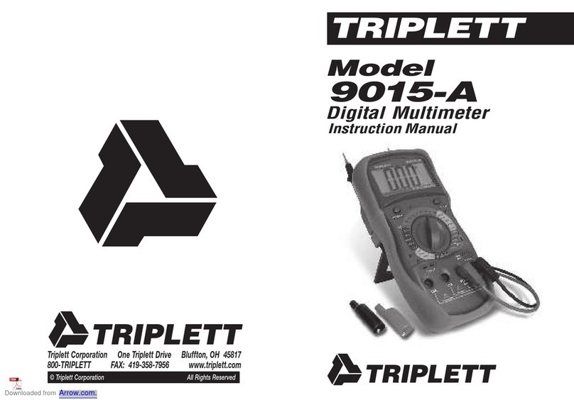
Triplett
Triplett 9015-A User manual
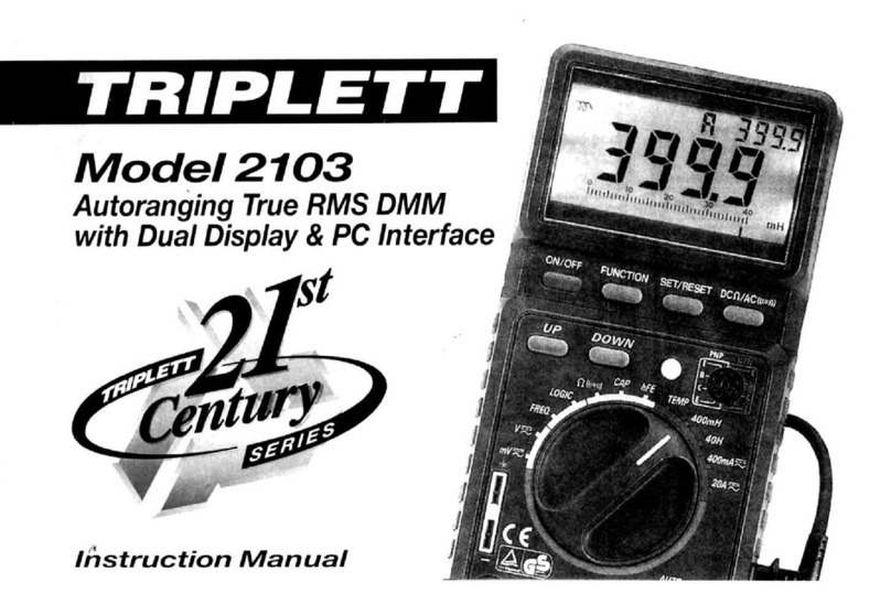
Triplett
Triplett 2103 User manual
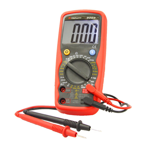
Triplett
Triplett 9007 User manual
Triplett
Triplett 9005-A User manual
Triplett
Triplett 2202 User manual
Popular Multimeter manuals by other brands

Gossen MetraWatt
Gossen MetraWatt METRAmax 6 operating instructions

PeakTech
PeakTech 4000 Procedure of calibration

YOKOGAWA
YOKOGAWA 90050B user manual

Gossen MetraWatt
Gossen MetraWatt METRALINE DMM16 operating instructions

Fluke
Fluke 8846A Programmer's manual

Tempo Communications
Tempo Communications MM200 instruction manual
