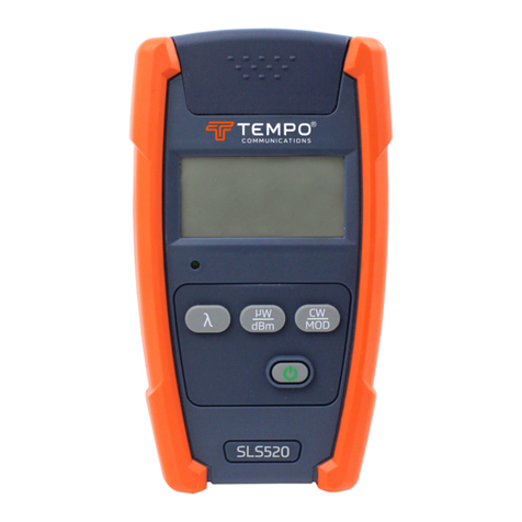
Tempo Communications SLS520 Reference guide

Printing Details:
Pages 2-3 are for printing, this information is NOT
to be printed.
Font Type: Prometo Bold (Headings & Subhead-
ings), Saira Regular (Body Text)
Format:
Page size: 150 mm x 85 mm
Artwork printed on both sides
Paper/Ink Details:
20 lb. standard paperweight, printed Black and
White on both Front and Back, laminated.
NAME SLS QUICK REFERENCE CARD
Part # 55500038
CONFIDENTIAL Proprietary information property of Tempo Communications Inc.,
not to be disclosed, copied or reproduced without permission.

Output Bulkhead
1310/1490/1550nm or 850/1300nm
Output Bulkhead
1625nm or 1650nm
External Power Output
Mamparo de salida
1310/1490/1550 nm o 850/1300 nm
Mamparo de salida
1625nm o 1650nm
Salida de alimentación externa
© 2022 Tempo Communications Inc. 01/22
QR-SLS
Visite www.tempocom.com para obtener el manual de
instrucciones completo.
[ ] Press the power button to turn the SLS on or o. Hold the power button for
two seconds to place the SLS into a constant on mode. Holding the power button
again for two seconds will revert to the auto o mode.
[ µW/dBm ] Press this key to toggle between dBm and µW.
[ CW/Mod ] Press this key to switch the output from CW to the desired tone
frequency.
[ ] Press this key to select the desired wavelength.
[ ] Pulse el botón de encendido para encender o apagar el SLS. Mantenga
pulsado el botón de encendido durante dos segundos para poner el SLS en modo
de encendido constante. Si de nuevo mantiene pulsado el botón de encendido
durante dos segundos, volverá al modo de apagado automático.
[ µW/dBm ] Pulse este botón para alternar entre dBm y µW.
[ CW/Mod ] Pulse este botón para cambiar la salida de CW a la frecuencia de
tono deseada.
[ ] Pulse este botón para seleccionar la longitud de onda deseada.
Keypad Functions
Funciones de los botones
OPM5XX Optical Power Meter Quick Reference
External Connector Instruction
①①Fiber Optic Input
OPM510 & OPM520 is available with SC fiber optic connector
(Interchangeable LC/ST/FC).
②②Ext. AC Power Jack
OPM510 & OPM520 can be operated with an External Power Adapter 9V
DC@250mA.
Keypad Functions
【【】】Push the power button to turn the OPM on or off. The default setting will
turn the OPM off after five minutes of inactivity. Hold the power button for two
seconds to place the OPM into a constant on mode. Holding the power button
again for two seconds will revert to the auto off mode.
【【dB/dBm】】Press this key to switch the measurement mode between absolute
power (dBm) and relative loss (dB). Hold the key until "HELD" is displayed.
【【Zero】】Press the Zero key to zero the OPM with the input port protected from
ambient light. A message of “SUCC”will be displayed upon successful zeroing. If
an “ERR”message appears check that the input port was in fact covered properly
and repeat the zeroing procedure.
【【Ref】】Press this key to display the reference value stored in memory. Hold the
key down until "HELD" appears in the display. When the OPM is switched to dB
mode, the LCD displays the difference in dB between the reference level and the
current input signal.
【【λ】】Press this key to select the wavelength to be measured.
The External Power LED Indicator will illuminate when the unit is powered by the
external power supply.
Do not connect an
APC ferrule to the
bulkhead.
No conecte una férula
APC al mamparo.
To avoid serious eye injury, never look directly into the bulkhead of ber
optic network equipment, test equipment, patch cords, or test jumpers.
• Always avoid looking directly into the bulkhead port.
• Always replace protective dust cover when the instrument is not being
used.
• Always avoid looking directly at the unconnected end of any ber optic
connector.
Para evitar lesiones oculares graves, nunca mire directamente al
mamparo de los equipos de red de bra óptica, equipos de ensayo, cables
de conexión o puentes de prueba. • Evite siempre mirar directamente al
puerto del mamparo.
• Vuelva a colocar siempre la cubierta protectora contra el polvo cuando
no se utilice el aparato.
• Evite siempre mirar directamente al extremo no conectado de cualquier
conector de bra óptica
Visit www.tempocom.com to obtain complete instruction manual.
1390 Aspen Way Vista, CA • 92081
Latin America Phone : 1 760 510 0558 | EMEA Phone: +44 (0) 1633 927 050
EMEA: Tempo Europe Limited • Brecon House
William Brown Close • Cwmbran • NP44 3AB • UK
©2022 Tempo Communications Inc. • An ISO 9001 Company

Cloison de sortie
1310/1490/1550nm ou 850/1300nm
Cloison de sortie
1625nm ou 1650nm
Sortie d’alimentation externe
Ausgangsschott
1310/1490/1550 nm oder 850/1300 nm
Ausgangsschott
1625nm oder 1650nm
Externer Stromausgang
© 2022 Tempo Communications Inc. 01/22
QR-SLS
Besuchen Sie www.tempocom.com für die vollständige
Bedienungsanleitung.
[ ] Appuyez sur le bouton d’alimentation pour allumer ou éteindre le SLS.
Maintenez le bouton d’alimentation enfoncé pendant deux secondes pour mettre
le SLS en mode constant allumé. Maintenez à nouveau le bouton d’alimentation
enfoncé pendant deux secondes pour revenir au mode d’arrêt automatique.
[ µW/dBm ] Appuyez sur cette touche pour basculer entre dBm et µW.
[ CW/Mod ] Appuyez sur cette touche pour commuter la sortie de CW à la
fréquence de tonalité souhaitée
[ ] Press this key to select the desired wavelength.
[ ] Drücken Sie die Ein/Aus-Taste, um das SLS ein- oder auszuschalten.
Halten Sie die Einschalttaste zwei Sekunden lang gedrückt, um das SLS in
einen dauerhaften Ein-Modus zu versetzen. Halten Sie die Ein/Aus-Taste
erneut zwei Sekunden lang gedrückt, um in den automatischen Abschaltmodus
zurückzukehren.
[ µW/dBm ] Drücken Sie diese Taste, um zwischen dBm und µW umzuschalten.
[ CW/Mod ] Drücken Sie diese Taste, um den Ausgang von CW auf die
gewünschte Tonfrequenz umzuschalten.
[ ] Drücken Sie diese Taste, um die gewünschte Wellenlänge auszuwählen.
Fonctions du clavier
Funktionen der Tastatur
OPM5XX Optical Power Meter Quick Reference
External Connector Instruction
①①Fiber Optic Input
OPM510 & OPM520 is available with SC fiber optic connector
(Interchangeable LC/ST/FC).
②②Ext. AC Power Jack
OPM510 & OPM520 can be operated with an External Power Adapter 9V
DC@250mA.
Keypad Functions
【【】】Push the power button to turn the OPM on or off. The default setting will
turn the OPM off after five minutes of inactivity. Hold the power button for two
seconds to place the OPM into a constant on mode. Holding the power button
again for two seconds will revert to the auto off mode.
【【dB/dBm】】Press this key to switch the measurement mode between absolute
power (dBm) and relative loss (dB). Hold the key until "HELD" is displayed.
【【Zero】】Press the Zero key to zero the OPM with the input port protected from
ambient light. A message of “SUCC”will be displayed upon successful zeroing. If
an “ERR”message appears check that the input port was in fact covered properly
and repeat the zeroing procedure.
【【Ref】】Press this key to display the reference value stored in memory. Hold the
key down until "HELD" appears in the display. When the OPM is switched to dB
mode, the LCD displays the difference in dB between the reference level and the
current input signal.
【【λ】】Press this key to select the wavelength to be measured.
The External Power LED Indicator will illuminate when the unit is powered by the
external power supply.
Ne connectez pas
de ferrule APC à la
cloison.
Schließen Sie keine
APC-Klemme an das
Schott an.
Pour éviter de graves blessures aux yeux, ne regardez jamais directement
dans la cloison de l’équipement de réseau à bre optique, de l’équipement
de test, des cordons de brassage ou des cavaliers de test. • Évitez toujours
de regarder directement dans le port de cloison.
• Replacez toujours le cache anti-poussière lorsque l’instrument n’est
pas utilisé.
• Évitez toujours de regarder directement l’extrémité non connectée d’un
connecteur de bre optique.
Um schwere Augenverletzungen zu vermeiden, blicken Sie niemals
direkt in die Trennwand von Glasfasernetzgeräten, Testgeräten,
Rangierkabeln oder Messbrücken.
• Vermeiden Sie es immer, direkt in die Schottönung zu schauen.
• Bringen Sie die Staubschutzabdeckung immer wieder an, wenn das
Gerät nicht verwendet wird.
• Vermeiden Sie es immer, direkt auf das nicht angeschlossene Ende eines
Glasfasersteckers zu schauen.
Visitez www.tempocom.com pour un manuel d’instructions complet.
1390 Aspen Way Vista, CA • 92081
Latin America Phone : 1 760 510 0558 | EMEA Phone: +44 (0) 1633 927 050
EMEA: Tempo Europe Limited • Brecon House
William Brown Close • Cwmbran • NP44 3AB • UK
©2022 Tempo Communications Inc. • An ISO 9001 Company
Other manuals for SLS520
1
This manual suits for next models
5
Table of contents
Other Tempo Communications Test Equipment manuals