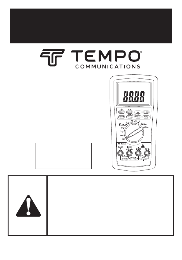
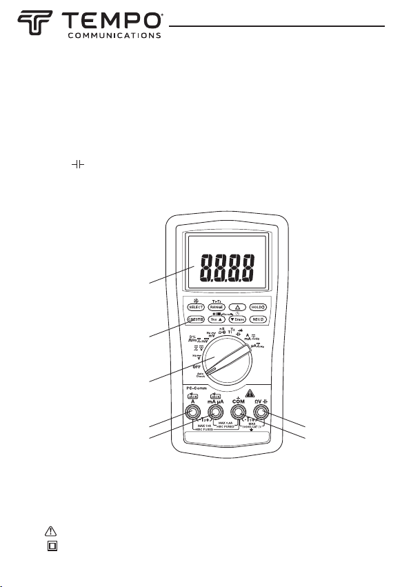
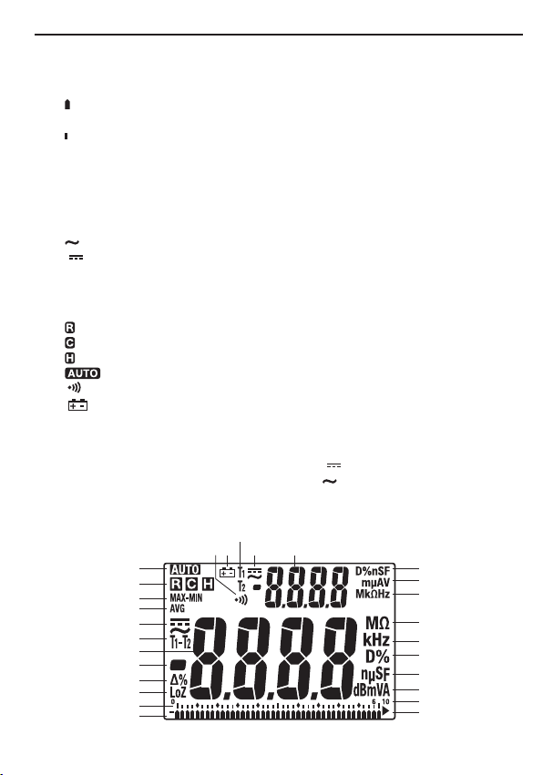
MM810A
8 9
The average-responding RMS calibrated method takes the average value of the input signal
after full wave rectication, multiplies it by 1.11, and displays the result. This method is
accurate if the input signal is a pure sine wave.
The true RMS-reading method uses internal circuitry to read the true RMS value. This method
is accurate, within the specied crest factor limitations, whether the input signal is a pure sine
wave, square wave, triangle wave, half wave, or signal with harmonics. The ability to read true
RMS provides much more measurement versatility. The Tempo MM810 is a true RMS meter.
The Waveforms and Crest Factors table shows some typical AC signals and their RMS values.
Measurement Categories
These denitions were derived from the international safety standard for insulation
coordination as it applies to measurement, control, and laboratory equipment. These
measurement categories are explained in more detail by the International Electrotechnical
Commission; refer to either of their publications: IEC 61010-1 or IEC 60664.
Measurement Category I
Signal level. Electronic and telecommunication equipment, or parts thereof. Some examples
include transient-protected electronic circuits inside photocopiers and modems.
Measurement Category II
Local level. Appliances, portable equipment, and the circuits they are plugged into. Some
examples include light xtures, televisions, and long branch circuits.
Measurement Category III
Distribution level. Permanently installed machines and the circuits they are hard-wired to.
Some examples include conveyor systems and the main circuit breaker panels of a building’s
electrical system.
Measurement Category IV
Primary supply level. Overhead lines and other cable systems. Some examples include cables,
meters, transformers, and other exterior equipment owned by the power utility.
10
AC Measurement
AC measurements are usually displayed as RMS (root mean square) values. The RMS value is equal to
the value of a DC waveform, which would deliver the same power if it replaced the time-varying wave-
form. Two AC measurement methods are average-responding RMS calibrated and true RMS-reading.
The average-responding RMS calibrated method takes the average value of the input signal after full
wave rectification, multiplies it by 1.11, and displays the result. This method is accurate if the input
signal is a pure sine wave.
The true RMS-reading method uses internal circuitry to read the true RMS value. This method is accu-
rate, within the specified crest factor limitations, whether the input signal is a pure sine wave, square
wave, triangle wave, half wave, or signal with harmonics.The ability to read true RMS provides much
more measurement versatility. The Greenlee DM-810A, DM-820A, DM-830A, and DML-430A are true
RMS meters.
The Waveforms and Crest Factors table shows some typical AC signals and their RMS values.
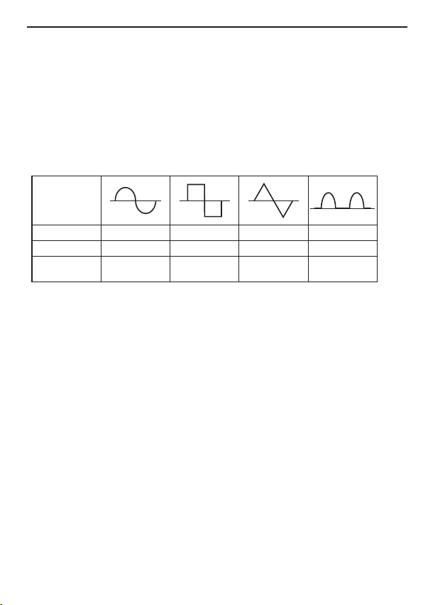
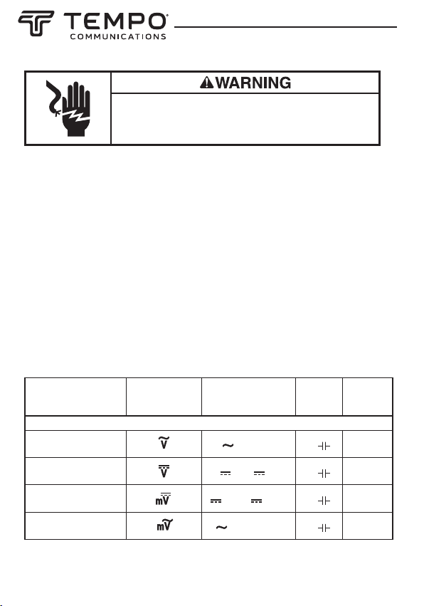
Waveforms and Crest Factors
Waveform
RMS Value 100 100 100 100
Average Value 90 100 87 64
Crest Factor*
(x)1.414 1 1.73 2
* The crest factor is the ratio of the peak value to the RMS value; it is represented by the Greek
letter x.
AC + DC True RMS
AC + DC true RMS calculates both of the AC and DC components given by the expression
when making measurements and responds accurately to the total effective RMS value regardless of the
waveform. Distorted waveforms with the presence of DC components and harmonics may cause:
• Transformers, generators, and motors to overheat
• Circuit breakers to trip prematurely
• Fuses to blow
• Neutrals to overheat due to the triplen harmonics present on the neutral
• Bus bars and electrical panels to vibrate
The DM-830A and DML-430A are AC + DC true RMS meters.