Temptek PTK Series User manual

TEMPTEK, INC.
525 East Stop 18 Road Greenwood, IN 46142
317-887-6352 fax: 317-881-1277
Service Department fax: 317-885-8683
www.Temptek.com
E-mail: [email protected]
I.O.M. #129 updated 09/30/2019
INSTRUCTION MANUAL • INSTALLATION • OPERATION • MAINTENANCE
Model:
Serial Number :

INSTRUCTION MANUAL
TOUGH TANK ‘PPT’
for TOWER WATER SYSTEMS
and CHILLED WATER SYSTEMS
With Checkmate Controller
COVERING
INSTALLATION
OPERATION
MAINTENANCE
TEMPTEK, INC.
525 East Stop 18 Road Greenwood, IN 46142
317-887-0729 fax: 317-881-1277
Service Department fax: 317-885-8683
www.Temptek.com
E-mail: [email protected]

Page: 3
TEMPTEK, INC.
525 East Stop 18 Road Greenwood, Indiana 46142
317-887-6352 Fax: 317-881-1277
Email: [email protected]
PTK Series Polyethylene Pump Tank Station with Checkmate Control System
TABLE OF CONTENTS
1.0 GENERAL 4
1.1 Safety 5
1.2 Efciency 5
1.3 Component Placement 5
2.0 INSTALLATION 7
2.1 Installation Drawings 8
2.2 Pump Base To Tank Mating Instructions 8
2.3 Plant Water Distribution 8
2.4 Water Treatment 8
2.5 Vacuum Breakers 9
2.6 Process Connections 9
2.7 Water Supply Connection 10
2.8 DrainAndOverowConnections 10
2.9 Electrical Connection 10
2.10 Probe Installation 11
3.0 OPERATIONS 12
3.1 General 13
3.2 Start Up/Operations Procedure 13
3.3 Instrument And Controls 16
4.0 MAINTENANCE 19
4.1 Preventive Maintenance 19
4.2 Pump Seal Service 20
4.3 Solenoid Valve Service 23
4.4 Instrument Calibration 24
5.0 ELECTRICAL
5.1 Electrical 26
6.0 APPENDIX 27
6.1 Typical Press Drop 28
6.2 Checkmate Second Set Point Guide 29

PTK Series Polyethylene Pump Tank Station with Checkmate Control System
Page: 4
TEMPTEK, INC.
525 East Stop 18 Road Greenwood, Indiana 46142
317-887-6352 Fax: 317-881-1277
Email: [email protected]
1.0 GENERAL
1.1 Safety
1.2 Efciency
1.3 Component Placement

Page: 5
TEMPTEK, INC.
525 East Stop 18 Road Greenwood, Indiana 46142
317-887-6352 Fax: 317-881-1277
Email: [email protected]
PTK Series Polyethylene Pump Tank Station with Checkmate Control System
1.1 SAFETY
A. It is important to become thoroughly familiar with this manual and the operating
characteristic of the equipment.
B. Several important references are made to safety considerations in this manual. It is the
owner’sresponsibilitytoassureproperoperatortraining,installation,operation,and
maintenance of the equipment.
C. Observe all warning and safety placards applied to the unit. Failure to observe warnings
can result in serious injury or death.
1.2 EFFICIENCY
A. Longtermefciencyofoperationislargelydeterminedbypropermaintenanceofthe
mechanical parts of the unit and the water quality.
B. TheFactoryacceptsnoresponsibilityforinefcientoperationordamagecausedby
improperinstallationoftheunitorforeignmaterialsintheprocessuid.
C. A water treatment system must be part of any pump tank system installation. The
servicesofaprofessionalqualiedwatertreatmentcompanyisrequiredtopreventscale,
corrosion, bacterial and biological growth.
The Factory highly recommends the services of a competent water treatment specialist
be obtained and his recommendations be followed. The Factory accepts no responsibility
forinefcientoperation,ordamagecausedbyforeignmaterialsorfailuretouseadequate
water treatment.
1.3 COMPONENT PLACEMENT
A. The TTK polyethylene pump tank station is designed to circulate temperature stabilized
uidthroughtheprocessresultinginprocesstemperaturecontrol.
B. Theabilityoftheequipmenttodothisissignicantlyaffectedbythemethodof
installation. The picture on the following page will give the reader an overview to the
major components of the unit.
C. If any questions arise, please contact The Factory Sales Representative or Service
Department.
D. TTKpumptanksystemsaredesignedforaspecicduty.Thecongurationofyour
system may differ from those in this manual. Contact the factory for additional
informationaboutyourspecicsystem.

PTK Series Polyethylene Pump Tank Station with Checkmate Control System
Page: 6
TEMPTEK, INC.
525 East Stop 18 Road Greenwood, Indiana 46142
317-887-6352 Fax: 317-881-1277
Email: [email protected]
Service Lid
Alarm
Process Pump
Tower/Evaporator Pump
CheckmateTM Control Panel
Polyethylene Reservoir
Control Console
Polyethylene Tank
Sight Glass
Temperature Gauges
Alarm Beacon
Drain Valve
Pump Assembly
Pressure Gauges
Electrical Cabinet
CheckmateTM Control Panel

Page: 7
TEMPTEK, INC.
525 East Stop 18 Road Greenwood, Indiana 46142
317-887-6352 Fax: 317-881-1277
Email: [email protected]
PTK Series Polyethylene Pump Tank Station with Checkmate Control System
2.0 INSTALLATION
2.1 Installation Drawings
2.2 Pump Base To Tank Mating Instructions
2.3 Plant Water Distribution
2.4 Water Treatment
2.5 Vacuum Breakers
2.6 Process Connections
2.7 Water Supply Connection
2.8 DrainAndOverowConnection
2.9 Electrical Connection
2.10 Probe Installation

PTK Series Polyethylene Pump Tank Station with Checkmate Control System
Page: 8
TEMPTEK, INC.
525 East Stop 18 Road Greenwood, Indiana 46142
317-887-6352 Fax: 317-881-1277
Email: [email protected]
2.1 INSTALLATION DRAWINGS
A. A number of typical drawings have been provided within this manual and with the unit. It
is necessary to review all drawings supplied to assure proper installation.
B. Contactthefactoryfortheelectricaldiagramthatisspecictoyourunit.
C. You will need the unit serial number when contacting the factory.
2.2 PUMP BASE TO TANK MATING INSTRUCTIONS
A. The following instructions detail the mating of the pump base to the polyethylene tank.
Refer to the drawing on the next page.
B. Unless otherwise noted, all necessary parts have been supplied by the factory.
C. Optional standby pump, alarm automatic water make-up and control console are shown
in the drawing. Not all systems are supplied with these options.
D. Pleasenotethatthecontrolconsoleisshown‘offbase’fordrawingpurpose’sonly.
E. Pump discharge manifold and sight glass are not shown in the drawing.
F. Mate the pump base to the tank.
2.3 PLANT WATER DISTRIBUTION
A. Please note that all material used in the installation should be rated for 150°F and 200 psi
minimum. Also note that the materials should have the equivalent diameter or larger of
their process connections.
B. Plant water distribution system design is critical to maximum performance of the system.
Careful attention should be paid to the pipe sizing, length of runs, number of elbows, tees
andvalving,asspecied.Normally,themostsuccessfulinstallationsarethosewhich
insuremaximumowsandminimumpressuredrops.
C. All water distribution piping should be properly braced to prevent sway and undue stress.
Brace all pipes to assure no excess loads or strains are applied to the unit. Insulate all
pipes to control excessive condensation and to help maintain set temperature to the
process (on chilled water systems).
2.4 WATER TREATMENT
A. A water treatment system must be part of any cooling tower or chilled water
system installation. The services of a professional qualied water treatment
company is required. A water treatment system typically consists of a plan to
control scaling, corrosion and biological growth. Failure to control the quality of
the water can result in premature unit failure, fouling of plant wide heat transfer
surfaces and biological growth that can cause sickness and even death.
B. Keeping the water in a cooling tower or chilled water system clean has benet
by reducing scale and fouling and ensuring that the cooling process is operating
Page: 9
TEMPTEK, INC.
525 East Stop 18 Road Greenwood, Indiana 46142
317-887-6352 Fax: 317-881-1277
Email: [email protected]
PTK Series Polyethylene Pump Tank Station with Checkmate Control System
efciently. Fouling can lead to a loss of plant performance.
C. The Manufacturer assumes no responsibility for equipment failures or other results from
untreated or improperly treated water.
D. Legionella. Cooling towers must be treated for and protected from Legionella. Follow
ASHRAE Standard 188P and/or CTI Guidelines WTB-14B, and /or OSHA Guidelines
Section III Chapter 7 and/or the recommendation of your professional water treatment
expert to prevent Legionella in your tower. Failure to prevent Legionella may result in
sickness or death.
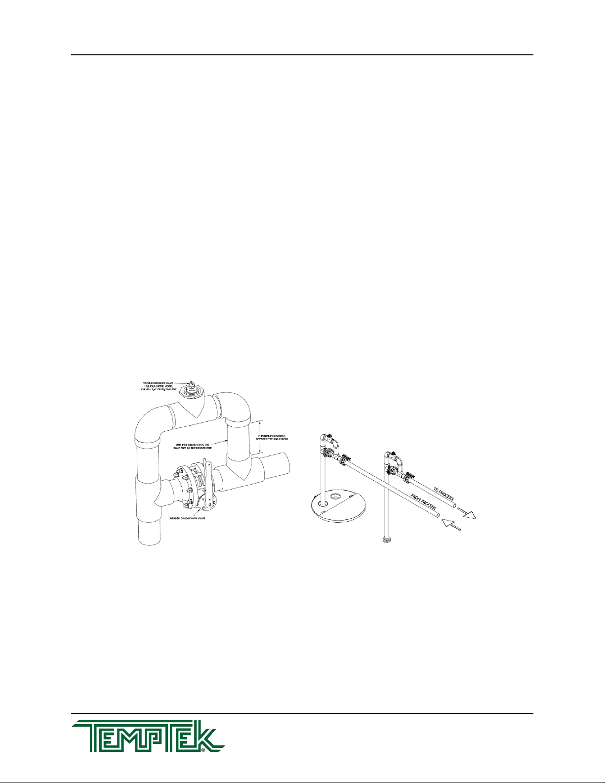
2.5 VACUUM BREAKERS
A. Vacuum breakers are required in all systems where overhead piping is used. Vacuum
breakerskeepthemainheadersystemfullofuidandpreventtankoverowduringshut
down periods.
B. The purpose of the vacuum breaker/anti-siphon (also called a drain-back dam) is to retain
water in the header system during shut-down periods and to allow for air purge which
eliminates shock to plumbing during start-up.
C. Itisnecessarytoinstallvacuumbreakersinthe‘supply’and‘return’lines.Thevacuum
breaker must be installed at the highest point in the system, nearest to the tanks to
bemosteffective.Anipplelengthof8inchesminimumisrequiredtocreatesufcient
vacuum to open the Cash Acme model VR-801.
2.6 PROCESS CONNECTIONS
A. Connect equipment process pump discharge port to main header supply line.
B. Connect equipment chiller or tower pump discharge port to chiller to tower cell inlet.
C. Install return line from the chiller or tower cell into the back 1/3 section of the cold tank
throughtheprovideopening.Returnlinefromtowerisgravityinducedowandslopingof
thispipeiscriticaltoproperowrates(minimum10%slope).
Typical Vacuum Breaker System

PTK Series Polyethylene Pump Tank Station with Checkmate Control System
Page: 10
TEMPTEK, INC.
525 East Stop 18 Road Greenwood, Indiana 46142
317-887-6352 Fax: 317-881-1277
Email: [email protected]
D. Install‘fromprocess”lineintotheback1/3sectionofthehotsideofthetankthroughthe
provided opening.
E. Note: all lines returning to the tank should extend below the water level, approximately
1.5 feet from the bottom of the tank.
F. Note: on a single pump system, the return line will connect directly to the chiller or tower
cell inlet. The line exiting out of the chiller or tower cell should be installed into the back
1/3 section of the cold side of the tank through the provided opening.
2.7 WATER MAKE-UP SUPPLY CONNECTION
A. Connecttheunit’s‘WATERSUPPLY’porttotheplant’scitywaterorwellwatersupply.
B. The factory recommend minimum operating water supply pressure requirement is
identiedontheunit’sdatapate.Thisisnormally20psi.
C. For units with electric automatic water make-up the water supply connection is located on
the reservoir. The make-up solenoid valve provides the water supply connection.
D. For units with mechanical automatic water make-up the water supply connection is
locatedonthereservoir.Abulk-headttingattachedtoaoatvalvelocatedinsidethe
tank provides the water supply connection.
E. Localcodesnormallyrequireabackowpreventiondevicebeinstalledinthewater
make-up line (customer supplied).
2.8 DRAIN AND OVERFLOW CONNECTIONS
A. Connectthedrainandoverowportstotheplant’sdrainagesystem.Thisisnormallya
sanitary sewer. Consult local codes.
2.9 ELECTRICAL CONNECTION
A. Electricalpowersupplyrequirementsareidentiedontheequipmentdataplate.
B. VERIFYTHATTHEAVAILABLEVOLTAGESUPPLYISTHESAMEASTHEUNIT’S
VOLTAGE REQUIREMENTS.
WARNING:Donotconnecttheunittoavoltagesupplysourcenotequaltotheunit’s
voltagerequirementsasspeciedontheunit’sdataplate.Useofincorrectvoltagewill
voidtheunit’swarrantyandcauseasignicanthazardthatmayresultinseriouspersonal
injury and unit damage.
C. For units with the optional central control console... a customer supplied four conductor
cable is required for connection to a customer supplied fused disconnecting means. The
fuseddisconnectingmeansshallbesizedandinstalledaccordingtotheunit’spower
supply requirements and local electrical codes. Connect the power cable to the terminal
L-1,L-2,L-3andthegroundlug(seegure2.9A).Somemodelsmayrequireapower
supply entry hole be made in the electrical cabinet.
D. For units without the optional central control console separate high voltage power with
customer supplied disconnecting means is required at each motor starter. Select a four

Page: 11
TEMPTEK, INC.
525 East Stop 18 Road Greenwood, Indiana 46142
317-887-6352 Fax: 317-881-1277
Email: [email protected]
PTK Series Polyethylene Pump Tank Station with Checkmate Control System
conductorcableratedforthemotor’spowerrequirementsandinstallaccordingtolocal
codes. Some motor starters may require a separate 110 volt line be installed.
E. GENERAL
1. Makecertainallgroundconnectionstotheunitareproperlyafxed.
2. Make certain power conductor, disconnecting means, and fusing are properly
sizedaccordingtotheunit’spowersupplyrequirements.
3. Makecertainallelectricalconnectionsaretightlyafxed.Anyloosewiring
connections must be tighten before engaging the power supply.
4. Make certain no moisture or standing water is present inside the electrical
cabinet.
2.10 PROBE INSTALLATION
A. For systems with the Checkmate control panel, two probes are shipped inside the
electrical cabinet and must be installed into the return distribution piping. These probes
are encased in a threaded bulb well.
B. P2 - From Process Probe: Install this probe into the from process return piping.
C. P4 - Tower/Evaporator Out Probe: Install this probe into the return line from the tower or
evaporator piping.

PTK Series Polyethylene Pump Tank Station with Checkmate Control System
Page: 12
TEMPTEK, INC.
525 East Stop 18 Road Greenwood, Indiana 46142
317-887-6352 Fax: 317-881-1277
Email: [email protected]
3.0 OPERATIONS
3.1 General
3.2 Start Up/Operations Procedure
3.3 Instruments And Controls

Page: 13
TEMPTEK, INC.
525 East Stop 18 Road Greenwood, Indiana 46142
317-887-6352 Fax: 317-881-1277
Email: [email protected]
PTK Series Polyethylene Pump Tank Station with Checkmate Control System
3.1 GENERAL
A. Failuretofollowthefactoryrequiredoperationproceduresmayadverselyaffecttheunit’s
ability to adequately distribute process water and may create a hazardous operating
condition which may result in unit damage and serious operator injury.
B. The operator must verify that all plumbing and electrical connections are in accordance to
section 2 of this manual and local codes.
C. The Operations segment of this manual is outlined below:
3.2 Start-up/operations procedure - follow this segment to start the unit after the
initialinstallation.Thissectionincludesinformationonsystemll,electricmotor
phasing(pumprotation)andprocessowadjustments.
3.3 Instrument and controls - follow this segment to start up and operate the
instrument and controls. This section includes feature explanations of PTS and
CPTS instruments.
3.2 START UP / OPERATIONS
A. System Checks
1. Before operating the pump tank station, verify the unit piping installation and unit
electrical installation is correct as outlined in section 2 of this manual.
2. System should be leak checked prior to pump tank system operation.
B. System Fill
1. All systems have automatic make-up. Some have mechanical and some system
useaoatswitchthatactivatesanelectricsolenoidvalve.
2. For units with electric automatic water make-up. Turn on plant water supply
to the tank and activate power supply to the tank. The water make-up solenoid
willopenandbeginllingthetank.Note: if electrical service is not connected the
tankwillnotll,manuallyllthetankuntilthewaterlevelisevenwiththelocation
of the external level switch tank.
3. For units with mechanical water make-up... turn on the plant water supply to
thetank.Thetankwilllluntilthewaterlevelreachesthemake-upoat.
4. For all units...whenthewaterlevelhasnearlyreachedthetopofthebafe,the
unit is ready to start.
C. Valve Placement
1. Opento100%thesuctionvalvesontheprocessandtower/evaporatorpumps.
2. Opento50%thedischargevalvesontheprocessandtower/evaporatorpumps.
3. Opento100%themain‘to’and‘from’processheadervalves.

PTK Series Polyethylene Pump Tank Station with Checkmate Control System
Page: 14
TEMPTEK, INC.
525 East Stop 18 Road Greenwood, Indiana 46142
317-887-6352 Fax: 317-881-1277
Email: [email protected]
4. Openasmanyprocessconnectionvalvesaspossibletoestablishawaterow
path.
D. Motor Rotation for Process Pump.
1. Activate the electrical power to the unit.
2. Turntheprocesspump‘on’momentarilyandthen‘off’again.Observetheshaftof
each motor. As the shaft slows to a stop, its rotation can be determined. Correct
rotation is clockwise when viewed from the rear of the motor.
3. If rotation for a motor is incorrect, disconnect power and reverse any two wires at
themotor’sstarterblock.
E. Motor Rotation For Tower / Evaporator Pump and Tower Fan
1. Activate the electrical power to the unit.
2. For tower system applications. It may be necessary to lower the setpoint on
the Checkmate control instrument.
3. Turnthepumporfan‘on’momentarily,then‘off’again.Observetheshaftofthe
motor. As the shaft slows to a stop, its rotation can be determined. For pump
motors, correct rotation is clockwise when viewed from the rear of the motor.
As for the cooling towers, correct rotation is counter clockwise or air should be
drawn from the bottom of the tower and out the top. For other tower cells, check
the tower cell manual for instructions on correct rotation.
4. If rotation for a motor is incorrect, disconnect power and reverse any two wires at
themotor’sstarterblock.
F. Pump Flow Adjustments
1. Whenstartingacentrifugalpump,itisimportanttoproperlysettheowrateto
prevent overloading of the pump motor. The following example is the start up
procedure for a two pump system.
2. Fully open the suction valves to the process and tower/evaporator pump. Note:
never allow the pumps to operate ‘dry’, as this can cause shaft seal failure.
3. Close the discharge valves of the process and tower/evaporator pumps. Note:
acentrifugalpumpcanbeoperatedwithnoowwithoutdamage,althoughthis
should not be for an extended period of time. Internal friction will cause the water
in the pump case to overheat.
4. Place an amp meter on one leg of the process pump wires at the motor starter.
Start the motor. Slowly open the discharge valve, allowing the process piping to
llwithwater.Afterowisestablished,continuetoopenthedischargevalve.The
ampdrawwillincreaseastheowincrease.Oncetherun-loadamprating,as
listed on the motor data tag, is reached, leave the valve in that position.

Page: 15
TEMPTEK, INC.
525 East Stop 18 Road Greenwood, Indiana 46142
317-887-6352 Fax: 317-881-1277
Email: [email protected]
PTK Series Polyethylene Pump Tank Station with Checkmate Control System
5. Note...ininitialstartup,thewaterusepointsmaynotbesufcienttofullyload
the motor. As you add use points, you should recheck the amp draw on the motor
and adjust the discharge valve as needed to prevent overloading the motor.
6. Repeat the procedure with the tower/evaporator pump.
7. On tower systems... the back pressure is very low on most tower cells. The
discharge valve may only be open one or two notches at full load.
8. Note... never operate a centrifugal pump without water in the case. Also, never
operate a centrifugal pump without checking for proper amp draw.
9. Note... always operate a centrifugal pump with the suction valve fully open.
Adjust the amp draw with the discharge valve starting from a closed position.
Starting from a wide open position can give a false reading and result in motor
overload.
10. Note... if during operations, the motor overload trips, the overloads will need to
be manually reset to restart operations. Once the pump is restarted, check for
excessive motor amps at the motor start block and throttle back the discharge
valve as needed.
G. Pump Tank Cycle
1. Two pump operation... the pump tank set is divided into two sections by a
bafe.Thesectionsarereferredtoasthe‘hotside’andthe‘coldside’.The
‘processpump’suctionisconnectedtothecoldsideandpumpswaterthrough
the distribution system. The water removes heat from the processes and returns
tothehotsideofthetank.The‘evaporatorpump’or‘towerpump’receiveswater
from the hot side of pumps the water through the chiller(s) or tower(s) and returns
the cooled water to the cold side of the tank.
2. One pump operation... the process pump suction is connected to the tank and
pumps water through the distribution system. The water removes heat from the
processes and passes through the chiller(s) or tower(s). The cooled water then
returns to the tank.
3. Standby pump operation... standby pumps are supplied as an option. If
installed on the system, they are supplied valved and wired such that switching
to back-up will take only a few minutes. A valve orientation guide is provided in
section 8 of this manual.
H. Valve Orientation for Normal and Standby Pump Operation
1. Refer to the following chart for proper position of the valves for normal and
standby operations:
I. Temperature and Pressure Gauges
1. Pressure gauges.The‘toprocess’pressuregaugesismountedonthe
dischargesideofthe‘toprocess’pumpandindicatespressuretothedistribution
system.The‘tower/evaporator’pressuregaugeismountedonthedischargeside
of the tower/evaporator pump and indicates pressure to the tower cell or chiller
evaporator.
PTK Series Polyethylene Pump Tank Station with Checkmate Control System
Page: 16
TEMPTEK, INC.
525 East Stop 18 Road Greenwood, Indiana 46142
317-887-6352 Fax: 317-881-1277
Email: [email protected]
2. Temperature gauges. On systems without the digital annunciator display,
temperature gauges are mounted on both sides of the tank. On systems with the
Checkmate display, temperature is indicated on the digital display window.
3.3 INSTRUMENT AND CONTROLS
A. Instrument and Control Operation
1. Determinepowerissuppliedtotheunit,(notetheilluminated‘power’led).Moving
the power switch to the On position will activate the system.
2. Each motor has a Top OperatorTMswitchoron/offoperatorwhichmustbe‘on’
for the pump to activate. These switches allow for selecting primary or standby
pumpsasneeded.Toturnoffaselectedpumpsimplyswitch‘off’thepump.
Moving the power switch to the Off position will activate the system and will
deactivateallpumpsthathavebeenswitched‘on’bytheirindividualtoggles.
3. Each pump is controlled by dedicated motor starters. To activate the pump, move
the power switch to the On position. To deactivate the pump move the power
switch to the Off position.
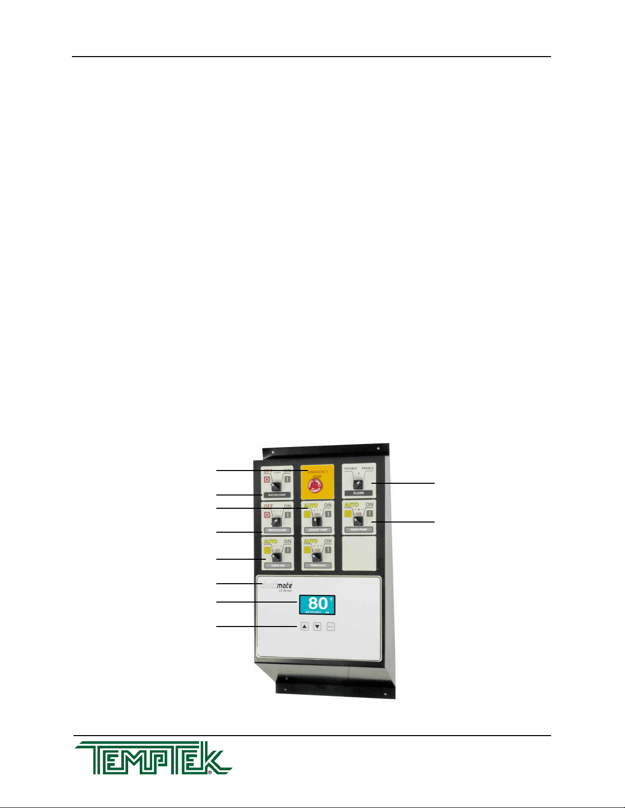
B. CHECKMATETM Control Panel
1. The CheckmateTM control panel is divided into two sections: the Top OperatorsTM
and the CheckmateTM instrument control.
2. The CheckmateTM control panel is mounted to the central control console cabinet
door on most installations.
Master Start / Stop
Emergency Stop
Process Pump On / Off
Standby Pump On / Off
CheckmateTM Instrument
Display Panel
Operator Controls
Tower Fan On / Off
Alarm Enable / Disable
Tower Pump On / Off
Page: 17
TEMPTEK, INC.
525 East Stop 18 Road Greenwood, Indiana 46142
317-887-6352 Fax: 317-881-1277
Email: [email protected]
PTK Series Polyethylene Pump Tank Station with Checkmate Control System
3. Top OperatorsTM are provided for pump, fan control, and system start and stop.
4. An emergency stop operator is provided for emergency system shut down.
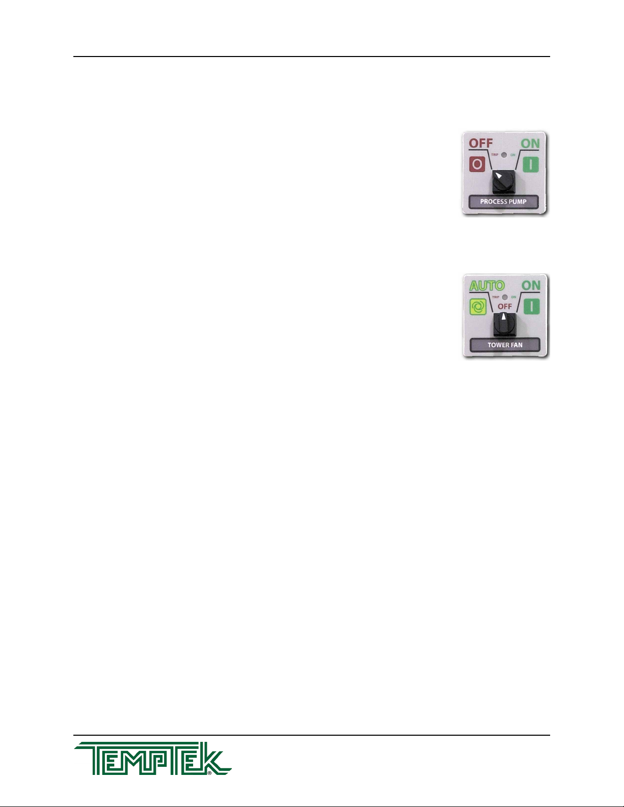
C. Top Operator for Pump Control
1. Tostartthepumpturntheswitchto“ON”.
2. Tostopthepumpturntheswitchto“OFF”.
3. Normalpumpoperationisindicatedbythe“GREEN”light.
Overloadconditionisindicatedbya“RED”light.
D. Top Operator for Tower Fan Control
1. Tostartthefanturntheswitchto“ON”.
2. Tostopthepumpturntheswitchto“OFF”.
3. Toautocontrolthetowerfanturntheswitchto“AUTO”.
The fan will be controlled by the system instrument.
4. Normalfanoperationisindicatedbythe“GREEN”light.
Overloadconditionisindicatedbya“RED”light.
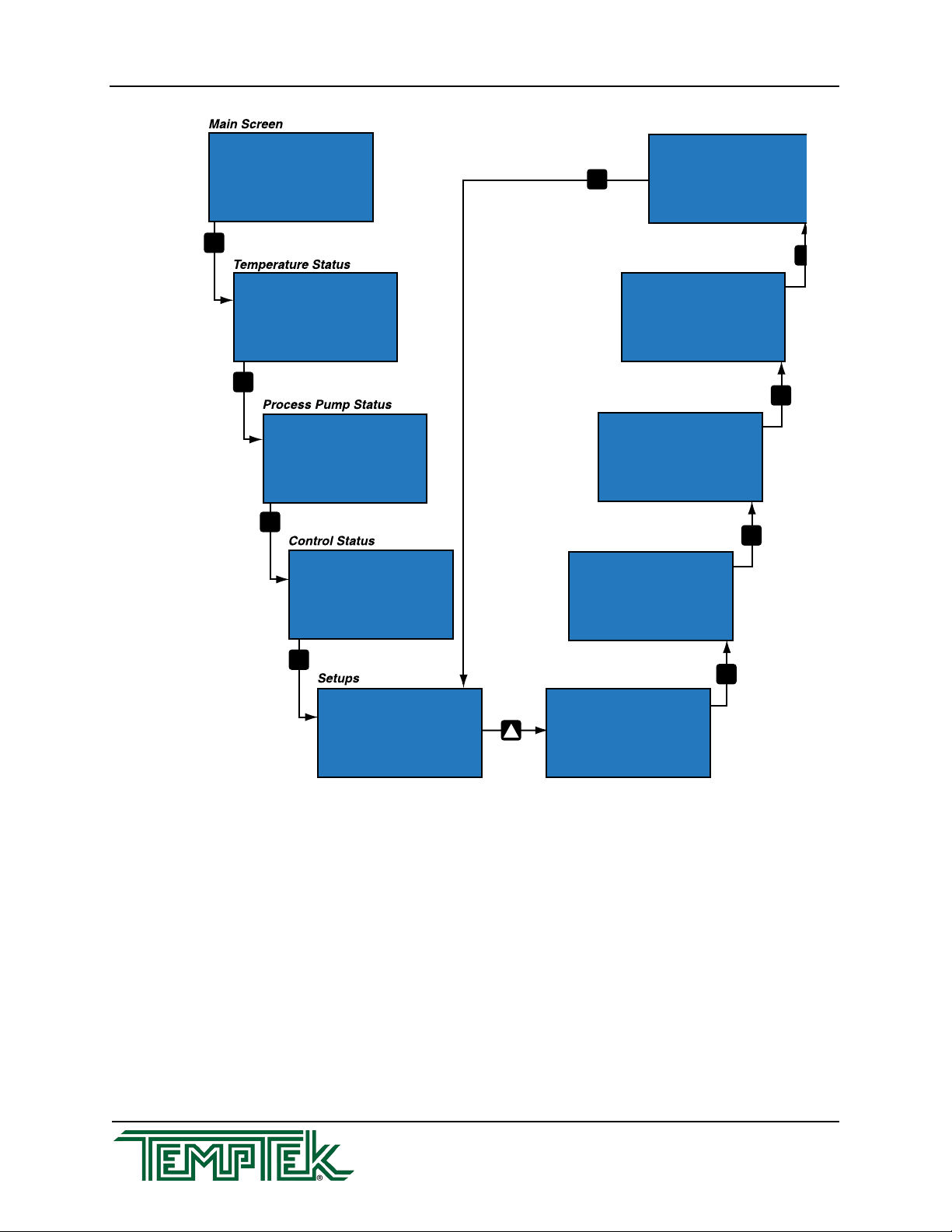
E. CheckmateTM Instrument Operation
1. Systeminformationisdisplayedinthecenterscreen.Usethe“SELECT”button
toscrollthroughthedifferentscreens.Usethe“UP”or“DOWN”arrowbuttonsto
set different operational parameters.
2. MAIN SCREEN. Displays the current To Process temperature in °F. The setpoint
temperature is also displayed.
3. TEMPERATURE STATUS SCREEN. Displays the From Process, To Process
and From Tower temperatures. On chilled water installations, there is a From
Chiller display instead of the From Tower display (as shown in the photo).
4. PROCESS PUMP STATUS SCREEN. Displays the on / off status of the process
pumps.
5. CONTROL STATUS SCREEN. Display the on / off status of the fans and process
pumps.
6. SETUP SCREENS. The operator can select this screen to enter the Setpoint
Temperature, the Hi Alarm and Low Alarm values. The Hi Alarm value is the
number of degree above the setpoint when the alarm will sound. The Lo Alarm
temperature is the number of degrees below the setpoint when the alarm will
sound.
PTK Series Polyethylene Pump Tank Station with Checkmate Control System
Page: 18
TEMPTEK, INC.
525 East Stop 18 Road Greenwood, Indiana 46142
317-887-6352 Fax: 317-881-1277
Email: [email protected]
F. Alarm system operation
1. The audible / visual alarm system is an optional component. If installed, there is a
visual and audible alarm beacon mounted on the control cabinet (typical).
2. Low pump pressure...the‘toprocess’pressurefallsbelowthepressureswitch
setting. The default is 40 PSI to open the contacts and 20 PSI to close the
contacts and trigger the alarm).
Causes of low pump pressure are: pump not operating due to tripped
overloads; impeller damaged or some internal pump obstruction; excessive
gpm.
SEL
SEL
SEL
SEL
SEL
SEL
SEL
SEL
Setpoints
Config 1
Delays
Communication
System Config
SEL
SYSTEM CONFIG
ADRESS 1
RATE 1
COMMUNICATION
PRESSURE 15
LEVEL 4
DELAYS
OUTPUT 1 PUMP
CONFIGURE 1
OUTPUT 2 FAN
OUTPUT 3 FAN
OUTPUT 4
OUTPUT 5
OUTPUT 6
PROCESS 84
ALT SP 40
HI ALARM 20
LO ALARM 20
SETPOINTS
PRESS TO ENTER
SETUP ACCESS
PROCESS
STATUS
84 94
TO FROM
TOWER 94
84
PUMP 1
PROCESS PUMPS
ON 17
PUMP 2 OFF 13
1 PUMP
OUTPUTS
ON 17
2 FAN ON 17
3 FAN ON 17
4 ON 17
5 ON 17
6 ON 17
84
SETPOINT 84
°F
RANGE 1 to 99
TYPE 1
1 - PTS
2 - CPTS

Page: 19
TEMPTEK, INC.
525 East Stop 18 Road Greenwood, Indiana 46142
317-887-6352 Fax: 317-881-1277
Email: [email protected]
PTK Series Polyethylene Pump Tank Station with Checkmate Control System
3. Low water level... the low water level alarm can be adjusted from 1 - 30 minutes.
If you set to 0, the alarm is disable.
Possible causes: defective makeup solenoid, defective level switch,
makeup water supply insufcient.
4.0 MAINTENANCE
4.1 PREVENTIVE MAINTENANCE
A. The following is a guide to preventive maintenance. The frequency of maintenance will
varywitheachapplication,installationconditions,owrates,hoursofuseandoperating
temperatures.
B. Preventive maintenance:
1. Lubricate all motors. Note: some motors are supplied with sealed bearings.
2. Tighten all wire terminations.
3. Clean and check motor starter and contactor contacts.
4. Check safety switch settings (ie. alarm thermostat).
5. Check all motors for correct amperage.
6. Clean water make-up solenoid valve.
7. Cleanandushunit.
PTK Series Polyethylene Pump Tank Station with Checkmate Control System
Page: 20
TEMPTEK, INC.
525 East Stop 18 Road Greenwood, Indiana 46142
317-887-6352 Fax: 317-881-1277
Email: [email protected]
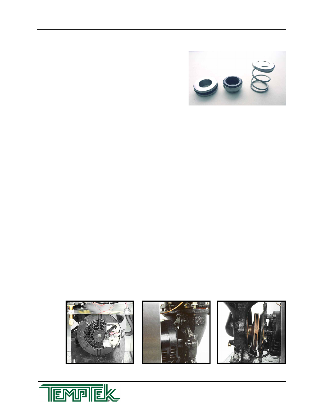
4.2 PUMP SEAL REPLACEMENT
A. The unit pump seal is a carbon/niresist shaft
seal assembly including a stationary member,
rotatingmemberandtensionspring(gure
4.2A).
B. The operator can determine the pump seal is
leakingwhenuidisidentiedleakingfrom
the pump case adapter.
C. Generally, a pump seal will leak due to
inadequateunitpressure,excessiveowandpooruidquality.
D. The operator should follow this procedure to replace the pump seal:
1. Disengageprocessoperations.Theoperatormustbecertainprocessuid
pressureisrelieved(pressuregaugereads“0”)andwatersystemowisshutoff
and all pressure relieved.
2. Disengage main power supply. The operator must verify the Power light on the
display is off.
3. Close the suction and discharge valves.
4. Drain pump. The pump can be drained by using the drain plug located on the
pump case.
5. Locate and remove the three motor wire leads from the motor wiring terminals.
The operator should note the wire terminal locations to ensure correct rewiring.
Thepowercordshouldberemovedfromthemotorhousing(gure4.2B).
6. Locate and remove the pump casing bolts. These bolts secure the motor and
motoradaptertothepumpcasing(gure4.2C).
7. Separate the motor and motor adapter from the pump casing to expose the pump
impeller(gure4.2D).Removethemotorandmotoradapterfromtheunitand
place on a workbench to continue the procedure.
8. Locate and remove the dust cap from motor end to expose slotted motor shaft.
Motor leads Figure 4.2B
Figure 4.2A
Impeller Figure 4.2DPump casing bolts Figure 4.2C
Table of contents
Popular Water System manuals by other brands

Everpure
Everpure QL1 Single Head EV9256-17Q Specification sheet

Everpure
Everpure Exubera Installation, use and maintenance handbook

Spectra Watermakers
Spectra Watermakers VENTURA 150 MPC-5000 owner's manual

EINHELL
EINHELL RG-WW 6536 operating instructions

Mi-T-M
Mi-T-M WTR Series Operator's manual

ZeroWater
ZeroWater Filter Bottle owner's manual

Greenfield
Greenfield ATLAS installation guide

Mueller
Mueller Hydro-Guard HG-6 Operating instructions manual

HoMedics
HoMedics Restore IB-RWS100A instruction manual
 installation manual")
Wolf
Wolf FWS-2-60(L) installation manual

Balboa
Balboa Wavezone3NE Installation Instructions and Maintenance Manual

Judo
Judo Bioquell PURE Installation and operating instructions


