Temptronic ThermoStream TP04300 Series User guide
Part Number:
4 Commerical Street, Sharon, MA 02067-1653 U.S.A.
Tel: (781) 688-2300 Fax: (781) 688-2301
http://www.temptronic.com LM01980
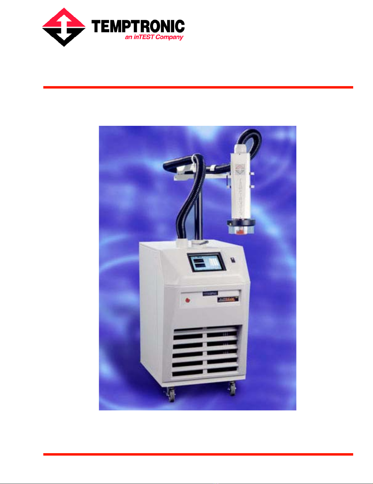
TP04300 Series ThermoStream®
Interface & Applications Manual
Revision L.
August 2005


TP04300 Series Interface & Applications Manual iii
. . . . .
. . . . . . . . . . . . . . . . . . . . . . . . . . . . . . . . . . .
Table of Contents
Preface
Overview . . . . . . . . . . . . . . . . . . . . . . . . . . . . . . . . . . . . . . . . . . . . . . . . . . . . . . . . . . . . . . . . . . . . . iii-ix
To Our Customers . . . . . . . . . . . . . . . . . . . . . . . . . . . . . . . . . . . . . . . . . . . . . . . . . . . . . . . . . . . . . . iii-ix
Temptronic Support. . . . . . . . . . . . . . . . . . . . . . . . . . . . . . . . . . . . . . . . . . . . . . . . . . . . . . . . . . . . . iii-x
Before You Call. . . . . . . . . . . . . . . . . . . . . . . . . . . . . . . . . . . . . . . . . . . . . . . . . . . . . . . . . . . . . . . . iii-xi
Chapter 1. Safety
Overview . . . . . . . . . . . . . . . . . . . . . . . . . . . . . . . . . . . . . . . . . . . . . . . . . . . . . . . . . . . . . . . . . . . . . 1-1
Section A. Safety Precautions, Warnings, Cautions
Warnings . . . . . . . . . . . . . . . . . . . . . . . . . . . . . . . . . . . . . . . . . . . . . . . . . . . . . . . . . . . . . . . . . . . . . 1-2
Cautions. . . . . . . . . . . . . . . . . . . . . . . . . . . . . . . . . . . . . . . . . . . . . . . . . . . . . . . . . . . . . . . . . . . . . . 1-5
Section B. CONSIGNES DE SÉCURITÉ POUR LE PERSONNEL EXPLOITANT
AVERTISSEMENT . . . . . . . . . . . . . . . . . . . . . . . . . . . . . . . . . . . . . . . . . . . . . . . . . . . . . . . . . . . . 1-7
ATTENTION. . . . . . . . . . . . . . . . . . . . . . . . . . . . . . . . . . . . . . . . . . . . . . . . . . . . . . . . . . . . . . . . . . 1-10
Section C. SICHERHEITSHINWEISE FÜR DAS BEDIENPERSONAL
WARNHINWEIS . . . . . . . . . . . . . . . . . . . . . . . . . . . . . . . . . . . . . . . . . . . . . . . . . . . . . . . . . . . . . . 1-12
HINWEIS . . . . . . . . . . . . . . . . . . . . . . . . . . . . . . . . . . . . . . . . . . . . . . . . . . . . . . . . . . . . . . . . . . . . 1-15
Section D. PRECAUCIONES DE SEGURIDAD PARA EL PERSONAL DE OPERACIONES
ADVERTENCIA. . . . . . . . . . . . . . . . . . . . . . . . . . . . . . . . . . . . . . . . . . . . . . . . . . . . . . . . . . . . . . . 1-16
PRECAUCION . . . . . . . . . . . . . . . . . . . . . . . . . . . . . . . . . . . . . . . . . . . . . . . . . . . . . . . . . . . . . . . . 1-19
Section E. Säkerhets Föreskrifter och Varningar, Varsamhet
Varningar. . . . . . . . . . . . . . . . . . . . . . . . . . . . . . . . . . . . . . . . . . . . . . . . . . . . . . . . . . . . . . . . . . . . . 1-20
Försiktighet och Varsamhet. . . . . . . . . . . . . . . . . . . . . . . . . . . . . . . . . . . . . . . . . . . . . . . . . . . . . . . 1-23
Chapter 2. Preparation For Use
Overview . . . . . . . . . . . . . . . . . . . . . . . . . . . . . . . . . . . . . . . . . . . . . . . . . . . . . . . . . . . . . . . . . . . . . 2-1
Section A. Initial System Setup Checklist
Setup Checklist . . . . . . . . . . . . . . . . . . . . . . . . . . . . . . . . . . . . . . . . . . . . . . . . . . . . . . . . . . . . . . . . 2-2
Section B. General Information
Overview . . . . . . . . . . . . . . . . . . . . . . . . . . . . . . . . . . . . . . . . . . . . . . . . . . . . . . . . . . . . . . . . . . . . . 2-3
Scope of Manual . . . . . . . . . . . . . . . . . . . . . . . . . . . . . . . . . . . . . . . . . . . . . . . . . . . . . . . . . . . . . . . 2-4
Related Manuals . . . . . . . . . . . . . . . . . . . . . . . . . . . . . . . . . . . . . . . . . . . . . . . . . . . . . . . . . . . . . . . 2-5
User/Owner Documentation . . . . . . . . . . . . . . . . . . . . . . . . . . . . . . . . . . . . . . . . . . . . . . . . . . . . . . 2-6
Access Levels . . . . . . . . . . . . . . . . . . . . . . . . . . . . . . . . . . . . . . . . . . . . . . . . . . . . . . . . . . . . . . . . . 2-7
Remote Operation Modes . . . . . . . . . . . . . . . . . . . . . . . . . . . . . . . . . . . . . . . . . . . . . . . . . . . . . . . . 2-8
Section C. Unpacking/Receipt of Shipment
Overview . . . . . . . . . . . . . . . . . . . . . . . . . . . . . . . . . . . . . . . . . . . . . . . . . . . . . . . . . . . . . . . . . . . . . 2-9
Receipt of Shipment . . . . . . . . . . . . . . . . . . . . . . . . . . . . . . . . . . . . . . . . . . . . . . . . . . . . . . . . . . . . 2-10
Unpacking Instructions . . . . . . . . . . . . . . . . . . . . . . . . . . . . . . . . . . . . . . . . . . . . . . . . . . . . . . . . . . 2-11

TABLE OF CONTENTS
iv TP04300 Series Interface & Applications Manual
Repackaging System. . . . . . . . . . . . . . . . . . . . . . . . . . . . . . . . . . . . . . . . . . . . . . . . . . . . . . . . . . . . . 2-13
Section D. Placement Requirements
Clearances, Dimensions, Weight . . . . . . . . . . . . . . . . . . . . . . . . . . . . . . . . . . . . . . . . . . . . . . . . . . . 2-14
Section E. Attaching the Thermal Cap and Shroud
. . . . . . . . . . . . . . . . . . . . . . . . . . . . . . . . . . . . . . . . . . . . . . . . . . . . . . . . . . . . . . . . . . . . . . . . . . . . . 2-15
Section F. Rear Panel, Air and Power Connections
. . . . . . . . . . . . . . . . . . . . . . . . . . . . . . . . . . . . . . . . . . . . . . . . . . . . . . . . . . . . . . . . . . . . . . . . . . . . . 2-17
Section G. Power Connections and Voltage Requirements
Overview. . . . . . . . . . . . . . . . . . . . . . . . . . . . . . . . . . . . . . . . . . . . . . . . . . . . . . . . . . . . . . . . . . . . . . 2-19
AC Power Standards. . . . . . . . . . . . . . . . . . . . . . . . . . . . . . . . . . . . . . . . . . . . . . . . . . . . . . . . . . . . . 2-20
Voltage Configurations. . . . . . . . . . . . . . . . . . . . . . . . . . . . . . . . . . . . . . . . . . . . . . . . . . . . . . . . . . . 2-20
To Measure Input Line Voltage . . . . . . . . . . . . . . . . . . . . . . . . . . . . . . . . . . . . . . . . . . . . . . . . . . . . 2-21
Configuring the Auto-Transformer Wires . . . . . . . . . . . . . . . . . . . . . . . . . . . . . . . . . . . . . . . . . . . . 2-23
Connecting the Main Power . . . . . . . . . . . . . . . . . . . . . . . . . . . . . . . . . . . . . . . . . . . . . . . . . . . . . . . 2-25
Section H. Air Connections
Overview. . . . . . . . . . . . . . . . . . . . . . . . . . . . . . . . . . . . . . . . . . . . . . . . . . . . . . . . . . . . . . . . . . . . . . 2-26
Compressed Air Standards . . . . . . . . . . . . . . . . . . . . . . . . . . . . . . . . . . . . . . . . . . . . . . . . . . . . . . . . 2-27
Connecting the Main Air Supply (Compressed Air) . . . . . . . . . . . . . . . . . . . . . . . . . . . . . . . . . . . . 2-28
Connecting Purged Air. . . . . . . . . . . . . . . . . . . . . . . . . . . . . . . . . . . . . . . . . . . . . . . . . . . . . . . . . . . 2-29
Section I. Rear Panel I/O Ports
I/O Ports Overview. . . . . . . . . . . . . . . . . . . . . . . . . . . . . . . . . . . . . . . . . . . . . . . . . . . . . . . . . . . . . . 2-30
Section J. Interfacing and Attaching Thermocouples
Overview. . . . . . . . . . . . . . . . . . . . . . . . . . . . . . . . . . . . . . . . . . . . . . . . . . . . . . . . . . . . . . . . . . . . . . 2-32
Sensor Interface Guidelines . . . . . . . . . . . . . . . . . . . . . . . . . . . . . . . . . . . . . . . . . . . . . . . . . . . . . . . 2-33
T-Type Sensors. . . . . . . . . . . . . . . . . . . . . . . . . . . . . . . . . . . . . . . . . . . . . . . . . . . . . . . . . . . . . . . . . 2-35
K-Type Sensors . . . . . . . . . . . . . . . . . . . . . . . . . . . . . . . . . . . . . . . . . . . . . . . . . . . . . . . . . . . . . . . . 2-38
RTD-Type Sensors . . . . . . . . . . . . . . . . . . . . . . . . . . . . . . . . . . . . . . . . . . . . . . . . . . . . . . . . . . . . . . 2-39
Diode-Type Sensors . . . . . . . . . . . . . . . . . . . . . . . . . . . . . . . . . . . . . . . . . . . . . . . . . . . . . . . . . . . . . 2-40
Non-Standard Thermocouples . . . . . . . . . . . . . . . . . . . . . . . . . . . . . . . . . . . . . . . . . . . . . . . . . . . . . 2-41
Section K. Static, Moisture, and Extreme Temperature Protection
Overview. . . . . . . . . . . . . . . . . . . . . . . . . . . . . . . . . . . . . . . . . . . . . . . . . . . . . . . . . . . . . . . . . . . . . . 2-43
Electrostatic Discharge (ESD) Protection . . . . . . . . . . . . . . . . . . . . . . . . . . . . . . . . . . . . . . . . . . . . 2-44
Moisture Protection . . . . . . . . . . . . . . . . . . . . . . . . . . . . . . . . . . . . . . . . . . . . . . . . . . . . . . . . . . . . . 2-45
Insulation (Minimizing Heat Conductivity) . . . . . . . . . . . . . . . . . . . . . . . . . . . . . . . . . . . . . . . . . . . 2-47
Section L. Turnkey Test Enclosures
Overview. . . . . . . . . . . . . . . . . . . . . . . . . . . . . . . . . . . . . . . . . . . . . . . . . . . . . . . . . . . . . . . . . . . . . . 2-49
ThermoFixture Enclosure. . . . . . . . . . . . . . . . . . . . . . . . . . . . . . . . . . . . . . . . . . . . . . . . . . . . . . . . . 2-50
Custom Thermal Test Enclosure . . . . . . . . . . . . . . . . . . . . . . . . . . . . . . . . . . . . . . . . . . . . . . . . . . . 2-51
Chapter 3. System Operation
Overview. . . . . . . . . . . . . . . . . . . . . . . . . . . . . . . . . . . . . . . . . . . . . . . . . . . . . . . . . . . . . . . . . . . . . . 3-1
Section A. Thermal Head and Manipulator (TP04300A)
Overview. . . . . . . . . . . . . . . . . . . . . . . . . . . . . . . . . . . . . . . . . . . . . . . . . . . . . . . . . . . . . . . . . . . . . . 3-2
Head and Manipulator Introduction . . . . . . . . . . . . . . . . . . . . . . . . . . . . . . . . . . . . . . . . . . . . . . . . . 3-3
Manipulator Locks . . . . . . . . . . . . . . . . . . . . . . . . . . . . . . . . . . . . . . . . . . . . . . . . . . . . . . . . . . . . . . 3-4
Stand Motion: Up/Down. . . . . . . . . . . . . . . . . . . . . . . . . . . . . . . . . . . . . . . . . . . . . . . . . . . . . . . . . . 3-7

. . . . .
TABLE OF CONTENTS
TP04300 Series Interface & Applications Manual v
Thermal Head Motion . . . . . . . . . . . . . . . . . . . . . . . . . . . . . . . . . . . . . . . . . . . . . . . . . . . . . . . . . . . 3-8
Section B. Operator Control Module (OCM)
Overview . . . . . . . . . . . . . . . . . . . . . . . . . . . . . . . . . . . . . . . . . . . . . . . . . . . . . . . . . . . . . . . . . . . . . 3-9
OCM User Interfaces. . . . . . . . . . . . . . . . . . . . . . . . . . . . . . . . . . . . . . . . . . . . . . . . . . . . . . . . . . . . 3-10
Touch Screen Alphanumeric “Keypad” . . . . . . . . . . . . . . . . . . . . . . . . . . . . . . . . . . . . . . . . . . . . . 3-12
Touch Screen Numeric “Keypad”. . . . . . . . . . . . . . . . . . . . . . . . . . . . . . . . . . . . . . . . . . . . . . . . . . 3-13
Section C. System Startup and Shutdown
Overview . . . . . . . . . . . . . . . . . . . . . . . . . . . . . . . . . . . . . . . . . . . . . . . . . . . . . . . . . . . . . . . . . . . . . 3-14
System Startup. . . . . . . . . . . . . . . . . . . . . . . . . . . . . . . . . . . . . . . . . . . . . . . . . . . . . . . . . . . . . . . . . 3-15
Password at Startup . . . . . . . . . . . . . . . . . . . . . . . . . . . . . . . . . . . . . . . . . . . . . . . . . . . . . . . . . . . . . 3-16
System Shutdown . . . . . . . . . . . . . . . . . . . . . . . . . . . . . . . . . . . . . . . . . . . . . . . . . . . . . . . . . . . . . . 3-17
Section D. System Status Screens
Overview . . . . . . . . . . . . . . . . . . . . . . . . . . . . . . . . . . . . . . . . . . . . . . . . . . . . . . . . . . . . . . . . . . . . . 3-18
Status Bar. . . . . . . . . . . . . . . . . . . . . . . . . . . . . . . . . . . . . . . . . . . . . . . . . . . . . . . . . . . . . . . . . . . . . 3-19
Jumbo Temperature Screens . . . . . . . . . . . . . . . . . . . . . . . . . . . . . . . . . . . . . . . . . . . . . . . . . . . . . . 3-20
Section E. Operator Screen
Operator Screen (Full Access). . . . . . . . . . . . . . . . . . . . . . . . . . . . . . . . . . . . . . . . . . . . . . . . . . . . . 3-21
Section F. Cycle Screen
Cycle Screen (Full Access) . . . . . . . . . . . . . . . . . . . . . . . . . . . . . . . . . . . . . . . . . . . . . . . . . . . . . . . 3-23
Section G. Utilities Screen
Overview . . . . . . . . . . . . . . . . . . . . . . . . . . . . . . . . . . . . . . . . . . . . . . . . . . . . . . . . . . . . . . . . . . . . . 3-25
Utilities Screen (Full Access) . . . . . . . . . . . . . . . . . . . . . . . . . . . . . . . . . . . . . . . . . . . . . . . . . . . . . 3-26
Auto-tune DUT Procedure Screen. . . . . . . . . . . . . . . . . . . . . . . . . . . . . . . . . . . . . . . . . . . . . . . . . . 3-28
Compressor startup (Heat/Cool) Screen . . . . . . . . . . . . . . . . . . . . . . . . . . . . . . . . . . . . . . . . . . . . . 3-29
Defrosting Procedure Screen. . . . . . . . . . . . . . . . . . . . . . . . . . . . . . . . . . . . . . . . . . . . . . . . . . . . . . 3-30
Changing the Password Screen . . . . . . . . . . . . . . . . . . . . . . . . . . . . . . . . . . . . . . . . . . . . . . . . . . . . 3-32
Select Access Level Screen. . . . . . . . . . . . . . . . . . . . . . . . . . . . . . . . . . . . . . . . . . . . . . . . . . . . . . . 3-33
Section H. Setup Screen
Overview . . . . . . . . . . . . . . . . . . . . . . . . . . . . . . . . . . . . . . . . . . . . . . . . . . . . . . . . . . . . . . . . . . . . . 3-34
Setup Screen (Full Access) . . . . . . . . . . . . . . . . . . . . . . . . . . . . . . . . . . . . . . . . . . . . . . . . . . . . . . . 3-35
Select DUT Sensor Screen . . . . . . . . . . . . . . . . . . . . . . . . . . . . . . . . . . . . . . . . . . . . . . . . . . . . . . . 3-41
Select a Setup file Screen . . . . . . . . . . . . . . . . . . . . . . . . . . . . . . . . . . . . . . . . . . . . . . . . . . . . . . . . 3-42
Save Setup, Rename Setup (Prevent Overwriting) . . . . . . . . . . . . . . . . . . . . . . . . . . . . . . . . . . . . . 3-43
Copy/Delete Setup Screen (Floppy Drive or USB port) . . . . . . . . . . . . . . . . . . . . . . . . . . . . . . . . . 3-44
Section I. History Screen
Overview . . . . . . . . . . . . . . . . . . . . . . . . . . . . . . . . . . . . . . . . . . . . . . . . . . . . . . . . . . . . . . . . . . . . . 3-45
History Screen (Full Access). . . . . . . . . . . . . . . . . . . . . . . . . . . . . . . . . . . . . . . . . . . . . . . . . . . . . . 3-46
To Review Live Data. . . . . . . . . . . . . . . . . . . . . . . . . . . . . . . . . . . . . . . . . . . . . . . . . . . . . . . . . . . . 3-48
To Review Saved (Datalogged) Data . . . . . . . . . . . . . . . . . . . . . . . . . . . . . . . . . . . . . . . . . . . . . . . 3-49
Section J. Datalog Screen
Overview . . . . . . . . . . . . . . . . . . . . . . . . . . . . . . . . . . . . . . . . . . . . . . . . . . . . . . . . . . . . . . . . . . . . . 3-50
Datalog Screen (Full Access) . . . . . . . . . . . . . . . . . . . . . . . . . . . . . . . . . . . . . . . . . . . . . . . . . . . . . 3-51
Loading a Saved Datalog file . . . . . . . . . . . . . . . . . . . . . . . . . . . . . . . . . . . . . . . . . . . . . . . . . . . . . 3-52
Copy/Delete a Datalog file . . . . . . . . . . . . . . . . . . . . . . . . . . . . . . . . . . . . . . . . . . . . . . . . . . . . . . . 3-53
Printing Datalogs. . . . . . . . . . . . . . . . . . . . . . . . . . . . . . . . . . . . . . . . . . . . . . . . . . . . . . . . . . . . . . . 3-55
Section K. Setting Up a New Test (Air Mode)

TABLE OF CONTENTS
vi TP04300 Series Interface & Applications Manual
. . . . . . . . . . . . . . . . . . . . . . . . . . . . . . . . . . . . . . . . . . . . . . . . . . . . . . . . . . . . . . . . . . . . . . . . . . . . . 3-57
Section L. Setting Up a New Test (DUT Mode)
. . . . . . . . . . . . . . . . . . . . . . . . . . . . . . . . . . . . . . . . . . . . . . . . . . . . . . . . . . . . . . . . . . . . . . . . . . . . . 3-58
Section M. Error Messages
. . . . . . . . . . . . . . . . . . . . . . . . . . . . . . . . . . . . . . . . . . . . . . . . . . . . . . . . . . . . . . . . . . . . . . . . . . . . . 3-59
Section N. Set Time, Date
. . . . . . . . . . . . . . . . . . . . . . . . . . . . . . . . . . . . . . . . . . . . . . . . . . . . . . . . . . . . . . . . . . . . . . . . . . . . . 3-60
Chapter 4. Remote Interfaces
Overview. . . . . . . . . . . . . . . . . . . . . . . . . . . . . . . . . . . . . . . . . . . . . . . . . . . . . . . . . . . . . . . . . . . . . . 4-1
Section A. Remote Interfaces, Overview and Assumptions
Remote Interfaces Overview . . . . . . . . . . . . . . . . . . . . . . . . . . . . . . . . . . . . . . . . . . . . . . . . . . . . . . 4-2
Section B. Enable/Disable Version 1 Software
. . . . . . . . . . . . . . . . . . . . . . . . . . . . . . . . . . . . . . . . . . . . . . . . . . . . . . . . . . . . . . . . . . . . . . . . . . . . . 4-4
Section C. Syntax
Syntax Overview . . . . . . . . . . . . . . . . . . . . . . . . . . . . . . . . . . . . . . . . . . . . . . . . . . . . . . . . . . . . . . . 4-6
Section D. Command Processing
Command Processing Overview. . . . . . . . . . . . . . . . . . . . . . . . . . . . . . . . . . . . . . . . . . . . . . . . . . . . 4-7
Section E. Error Reporting (Software Version 3)
. . . . . . . . . . . . . . . . . . . . . . . . . . . . . . . . . . . . . . . . . . . . . . . . . . . . . . . . . . . . . . . . . . . . . . . . . . . . . 4-8
Section F. Maximizing Communications Throughput
. . . . . . . . . . . . . . . . . . . . . . . . . . . . . . . . . . . . . . . . . . . . . . . . . . . . . . . . . . . . . . . . . . . . . . . . . . . . . 4-9
Section G. IEEE-488.2 Interface
Set: Bus Address; Baud 9600. . . . . . . . . . . . . . . . . . . . . . . . . . . . . . . . . . . . . . . . . . . . . . . . . . . . . . 4-10
Demonstration Program . . . . . . . . . . . . . . . . . . . . . . . . . . . . . . . . . . . . . . . . . . . . . . . . . . . . . . . . . . 4-10
Section H. Serial Interface
Serial Interface Connector . . . . . . . . . . . . . . . . . . . . . . . . . . . . . . . . . . . . . . . . . . . . . . . . . . . . . . . . 4-11
Serial Interface Parameters. . . . . . . . . . . . . . . . . . . . . . . . . . . . . . . . . . . . . . . . . . . . . . . . . . . . . . . . 4-11
Demonstration Program . . . . . . . . . . . . . . . . . . . . . . . . . . . . . . . . . . . . . . . . . . . . . . . . . . . . . . . . . . 4-12
Section I. Remote Command Set
Remote Commands Overview . . . . . . . . . . . . . . . . . . . . . . . . . . . . . . . . . . . . . . . . . . . . . . . . . . . . . 4-13
IEEE Mandatory Commands . . . . . . . . . . . . . . . . . . . . . . . . . . . . . . . . . . . . . . . . . . . . . . . . . . . . . . 4-14
RS-232C Serial Commands . . . . . . . . . . . . . . . . . . . . . . . . . . . . . . . . . . . . . . . . . . . . . . . . . . . . . . . 4-16
Device Specific Commands . . . . . . . . . . . . . . . . . . . . . . . . . . . . . . . . . . . . . . . . . . . . . . . . . . . . . . . 4-17
Section J. Ethernet 10/100 BaseT Interface
Ethernet Overview . . . . . . . . . . . . . . . . . . . . . . . . . . . . . . . . . . . . . . . . . . . . . . . . . . . . . . . . . . . . . . 4-27
Ethernet Connector. . . . . . . . . . . . . . . . . . . . . . . . . . . . . . . . . . . . . . . . . . . . . . . . . . . . . . . . . . . . . . 4-28
Ethernet Log In/Log Out . . . . . . . . . . . . . . . . . . . . . . . . . . . . . . . . . . . . . . . . . . . . . . . . . . . . . . . . . 4-29
Section K. MCT Interface
MCT Interface . . . . . . . . . . . . . . . . . . . . . . . . . . . . . . . . . . . . . . . . . . . . . . . . . . . . . . . . . . . . . . . . . 4-30
Chapter 5. Routine Maintenance
Overview. . . . . . . . . . . . . . . . . . . . . . . . . . . . . . . . . . . . . . . . . . . . . . . . . . . . . . . . . . . . . . . . . . . . . . 5-1

. . . . .
TABLE OF CONTENTS
TP04300 Series Interface & Applications Manual vii
Section A. Maintenance Log
. . . . . . . . . . . . . . . . . . . . . . . . . . . . . . . . . . . . . . . . . . . . . . . . . . . . . . . . . . . . . . . . . . . . . . . . . . . . . 5-2
Section B. Inspection and Cleaning
. . . . . . . . . . . . . . . . . . . . . . . . . . . . . . . . . . . . . . . . . . . . . . . . . . . . . . . . . . . . . . . . . . . . . . . . . . . . . 5-3
Section C. Side Panel and Cover Removal
. . . . . . . . . . . . . . . . . . . . . . . . . . . . . . . . . . . . . . . . . . . . . . . . . . . . . . . . . . . . . . . . . . . . . . . . . . . . . 5-4
Section D. Air Path Maintenance
Overview . . . . . . . . . . . . . . . . . . . . . . . . . . . . . . . . . . . . . . . . . . . . . . . . . . . . . . . . . . . . . . . . . . . . . 5-5
Drain Moisture from Pneumatics Filter Elements. . . . . . . . . . . . . . . . . . . . . . . . . . . . . . . . . . . . . . 5-6
Pneumatics Filter Element Replacement. . . . . . . . . . . . . . . . . . . . . . . . . . . . . . . . . . . . . . . . . . . . . 5-8
Air Dryer: Post Filter Replacement. . . . . . . . . . . . . . . . . . . . . . . . . . . . . . . . . . . . . . . . . . . . . . . . . 5-9
Muffler Replacement. . . . . . . . . . . . . . . . . . . . . . . . . . . . . . . . . . . . . . . . . . . . . . . . . . . . . . . . . . . . 5-10
Section E. Verification of DUT, RTD, and Diode Sensors
Overview . . . . . . . . . . . . . . . . . . . . . . . . . . . . . . . . . . . . . . . . . . . . . . . . . . . . . . . . . . . . . . . . . . . . . 5-11
DUT Verification Introduction . . . . . . . . . . . . . . . . . . . . . . . . . . . . . . . . . . . . . . . . . . . . . . . . . . . . 5-12
Low Temperature Verification . . . . . . . . . . . . . . . . . . . . . . . . . . . . . . . . . . . . . . . . . . . . . . . . . . . . 5-13
High Temperature Verification . . . . . . . . . . . . . . . . . . . . . . . . . . . . . . . . . . . . . . . . . . . . . . . . . . . . 5-17
Section F. Calibration
Overview . . . . . . . . . . . . . . . . . . . . . . . . . . . . . . . . . . . . . . . . . . . . . . . . . . . . . . . . . . . . . . . . . . . . . 5-20
Calibration Introduction . . . . . . . . . . . . . . . . . . . . . . . . . . . . . . . . . . . . . . . . . . . . . . . . . . . . . . . . . 5-21
Calibration Select Sensor Screen. . . . . . . . . . . . . . . . . . . . . . . . . . . . . . . . . . . . . . . . . . . . . . . . . . . 5-22
Air Sensor Calibration (Air Mode) . . . . . . . . . . . . . . . . . . . . . . . . . . . . . . . . . . . . . . . . . . . . . . . . . 5-23
Sensor Calibration: Type T, Type K Thermocouples (DUT Mode) . . . . . . . . . . . . . . . . . . . . . . . . 5-25
RTD Sensor Calibration (DUT Mode) . . . . . . . . . . . . . . . . . . . . . . . . . . . . . . . . . . . . . . . . . . . . . . 5-32
Diode Sensor Calibration (DUT Mode) . . . . . . . . . . . . . . . . . . . . . . . . . . . . . . . . . . . . . . . . . . . . . 5-39
TC Meter Calibration (TC Meter Mode). . . . . . . . . . . . . . . . . . . . . . . . . . . . . . . . . . . . . . . . . . . . . 5-46
MSDS Overview . . . . . . . . . . . . . . . . . . . . . . . . . . . . . . . . . . . . . . . . . . . . . . . . . . . . . . . . . . . . . . . A-1
Drawings Overview. . . . . . . . . . . . . . . . . . . . . . . . . . . . . . . . . . . . . . . . . . . . . . . . . . . . . . . . . . . . . B-1
Backwards Compatibility . . . . . . . . . . . . . . . . . . . . . . . . . . . . . . . . . . . . . . . . . . . . . . . . . . . . . . . . C-1
Application Notes Overview. . . . . . . . . . . . . . . . . . . . . . . . . . . . . . . . . . . . . . . . . . . . . . . . . . . . . . D-1
Temperature Control Using the TP04300 System. . . . . . . . . . . . . . . . . . . . . . . . . . . . . . . . . . . . . . D-2
Air Mode . . . . . . . . . . . . . . . . . . . . . . . . . . . . . . . . . . . . . . . . . . . . . . . . . . . . . . . . . . . . . . . . . . . . . D-2
DUT Mode. . . . . . . . . . . . . . . . . . . . . . . . . . . . . . . . . . . . . . . . . . . . . . . . . . . . . . . . . . . . . . . . . . . . D-3
Temperature Control Troubleshooting . . . . . . . . . . . . . . . . . . . . . . . . . . . . . . . . . . . . . . . . . . . . . . D-6
TC Meter Mode. . . . . . . . . . . . . . . . . . . . . . . . . . . . . . . . . . . . . . . . . . . . . . . . . . . . . . . . . . . . . . . . D-8

TABLE OF CONTENTS
viii TP04300 Series Interface & Applications Manual

TP04300 Series Interface & Applications Manual ix
. . . . .
. . . . . . . . . . . . . . . . . . . . . . . . . . . . . . . . . . .
Preface
Overview
In this section The following is covered in this preface
To Our Customers
This Manual The purpose of this manual is to help obtain the greatest return on your investment.
Temptronic suggests that operators, supervisors, and technicians responsible for operating and
maintaining this equipment become familiar with the contents of these manuals prior to using
the equipment.
This manual instructs how to setup, operate and perform routine maintenance for the TP04300
ThermoStream® System(s).
Other Manuals
in the Set Following is the complete list of manuals which make up this information set
Topic See Page
To Our Customers ix
Temptronic Support x
Before You Call xi
Manual Name Part Number
TP04300 Operator’s Manual LM01970
TP04300 Interface and Applications Manual LM01980
TP04300 Service Manual LM02290

PREFACE
Temptronic Support
x TP04300 Series Interface & Applications Manual
Temptronic Support
Introduction Temptronic is committed to assisting end users and technicians to maintain operational
systems which are highly reliable. Temptronic offers the following support services.
Customer Training Formal technical training courses are available. The training courses cover the theory of
operation and the maintenance procedures for the System. For further information, contact the
Temptronic Service Department.
Repair Service Temptronic maintains a fully equipped repair center at the factory plant for warranty and non-
warranty repairs. For further information on module and circuit board repairs, our exchange
program, and the availability of spare parts, contact the Temptronic Service Department.
Before returning any module or circuit board for repair, contact the Temptronic Service
Department to obtain a return authorization (RA) number.
Spare Parts Electrical and mechanical replaceable parts for the System can be obtained through your local
Temptronic representative, or directly from the Temptronic Service Department. When
ordering, be sure to specify the:
• Quantity
• Temptronic part number
• Description
• Reference designation (if any)
• Complete model number and serial number of your system
For your convenience, Spare Parts Kits are available for different levels of service activity.
Technical Support Contact the Temptronic Service Department by one of the following means:
ATTENTION
1. Please note that the 1-800 toll free telephone number is dedicated to Service Department
calls only. It is not possible to dial this number and to transfer to other departments within
Temptronic.
2. The main telephone number, 781 688-2300, should be used for non-service related calls.
Temptronic Technical Support
1-800 558-5080 Toll Free Telephone (service calls only)
781 688-2302 Service FAX line
781 688-2300 Temptronic Corp. Main Telephone line
. . . . .
PREFACE
Before You Call
TP04300 Series Interface & Applications Manual xi
Before You Call
Introduction You can help us support your machine in timely fashion by having on hand specific
information when calling in:
• Software Version
• System Model Number
System Model
Number A modular system design allows the customer to select options or features as desired for a
given installation or application
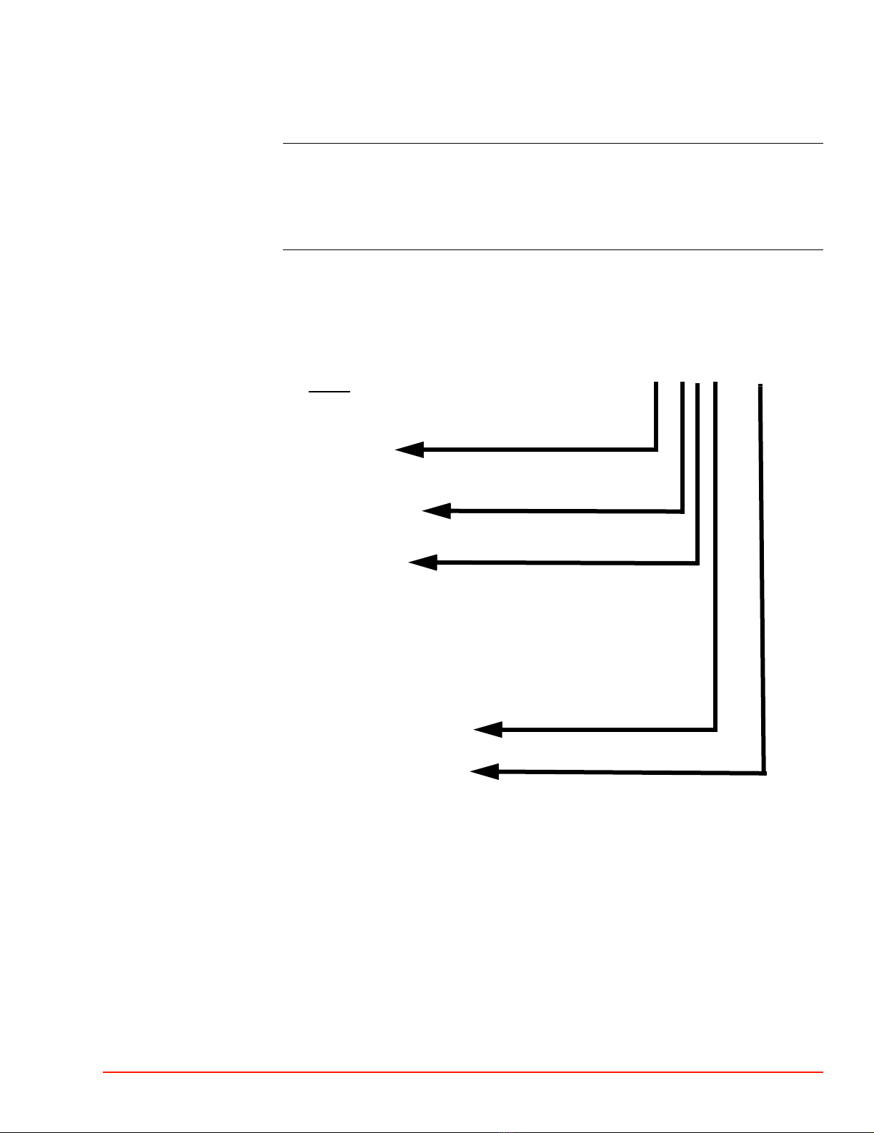
The System Model Number Designation, printed on the TP04300 nameplate, reflects the
configuration at time of shipment:
TP04300 A- 3 X 3 2 - X
TEMPERATURE RANGE:
“A” -80° /+225 °
THERMAL HEAD:
“3” Quick Response
ARM ASSEMBLY:
“C” Fully articulated (wide range of motion), manually locking
“0” No Arm, Head with 4 foot hose
“1” No Arm, Head with 8 foot hose
OPERATOR CONSOLE DISPLAY:
“3” Full color, touch screen
POWER CONFIGURATION:
“2”. 235 to 250 Vac, 60 Hz, 30 amp, single phase
“3”. 235 to 250 Vac, 50 Hz, 30 amp, single phase
“4”. 200 to 214 Vac, 60 Hz, 30 amp, single phase
“5”. 200 to 214 Vac, 50 HZ, 30 amp, single phase
“6”. 215 to 224 Vac, 60 HZ, 30 amp, single phase
“7”. 215 to 224 Vac, 50 HZ, 30 amp, single phase
“8”. 225 to 234 Vac, 60 HZ, 30 amp, single phase
“9”. 225 to 234 Vac, 50 Hz, 30 amp, single phase
CODE

PREFACE
Before You Call
xii TP04300 Series Interface & Applications Manual

TP04300 Series Interface & Applications Manual 1-1
1
. . . . .
. . . . . . . . . . . . . . . . . . . . . . . . . . . . . . . . . . .
Safety
Overview
Introduction This Chapter covers all the safety Warnings and Cautions for the TP04300 ThermoStream.
In this Chapter This Chapter is divided into the following Sections:
Topic See Page
Safety Precautions, Warnings, Cautions 2
CONSIGNES DE SÉCURITÉ POUR LE PERSONNEL EXPLOITANT 7
SICHERHEITSHINWEISE FÜR DAS BEDIENPERSONAL 12
PRECAUCIONES DE SEGURIDAD PARA EL PERSONAL DE
OPERACIONES 16
Säkerhets Föreskrifter och Varningar, Varsamhet 20

1SAFETY
Warnings
1-2 TP04300 Series Interface & Applications Manual
Section A:
. . . . . . . . . . . . . . . . . . . . . . . . . . . . . . . . . . .
Safety Precautions, Warnings, Cautions
Warnings
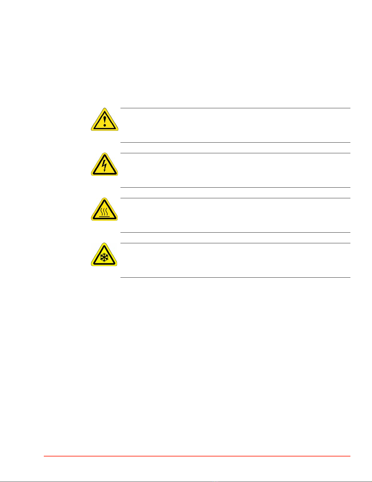
WARNING
WARNING: Refer to Accompanying Documentation
Electrical Hazard
WARNING: High Voltage, Electrical Shock Hazard
Hot Surface
WARNING: Hot Surface
Cold Surface
WARNING: Cold Surface
WARNING 1: The locations of potentially dangerous voltages and other hazards such as hot
surfaces or cold surfaces or compressed air/gases/vapors at high pressures are identified and
labeled on the equipment. Be careful to observe these warnings when installing, operating,
maintaining, or servicing the equipment. Observe all warnings given in this manual. Only use
the equipment for the intended usages specified by the manufacturer.
WARNING 2: The troubleshooting instructions contained in this manual can involve a
possible contact with electrical power at high voltages, compressed air at high pressures, and
refrigerants at high or vacuum pressures. These hazards can be injurious or dangerous to life.
Do not perform these instructions unless you qualify to do them.
WARNING 3: To avoid shock hazard, the equipment must be grounded with an adequate
earth ground per local electrical codes.
WARNING 4: When connecting thermocouple sensors to the Device Under Test (DUT),
electrically isolate the sensors to protect operators from contact with any hazardous voltages
which could be present at the DUT site.
WARNING 5: Parts inside the thermal head operate at extremely hot and cold temperatures
and are dangerous to touch. Do not perform any maintenance inside the thermal head until the
system is turned off. Wait until the head parts have reached a safe and stable temperature near
ambient.
WARNING 6: Keep your fingers out of the space between the thermal cap on the head and the
DUT site during the up/down motion of the System’s thermal head.

. . . . .
SAFETY
Warnings
TP04300 Series Interface & Applications Manual 1-3
WARNING 7: Per SEMI S2-93A, energized electrical work (“Hot Work”) is specified by
Type as follows:
WARNING 8: Where equipment must be fully de-energized (electrically “cold”) to allow safe
entry into system, the following Lockout/Tagout procedure is required per OSHA 29 CFR
1910: a) For devices with a power cord which “unplugs” from a service receptacle, the end
user must supply and tag a Plug lockout shell which completely encloses the plug and prevents
accidental reconnection; b) for devices hardwired to the electrical supply, the end user must
install and tag a power disconnect switch with a lock out position, or install and tag a circuit
breaker with a lock out position, to prevent accidental reconnection.
WARNING 9: To de-energize the System for safe replacement of a module, turn off the ac
power (cease operations and power down), then turn off the System’s air pressure supply, then
bleed all air from System by turning on ac power just long enough to exhaust all air from
System. Now disconnect both the main power supply cord and disconnect the air supply line
from air supply port fitting on the rear frame module. The only stored energy remaining in the
System will then be that within some electrical capacitors. One large capacitor is near the
System’s air-chiller compressor. Other large capacitors are in the System’s electrical power
supplies.
WARNING 10: If service of the Air Chiller Module is required, only a licensed (and/or EPA
Certified) refrigeration service person, authorized by the Temptronic Corporation, is qualified
to perform any charging or handling of the refrigerants in the System.
WARNING 11: Under no circumstances (leak testing or any other purpose) is the Air Chiller
Module to be charged with any gas at a pressure above 150 psig (10.34 bar).
WARNING 12: The Air Chiller Module acts as a counterbalance for the Thermal Head
Assembly. Before removing the Air Chiller Module, make sure the horizontal arm is down on
the vertical C-arm at its lower limit, and the thermal head is in next to the horizontal arm and
stowed toward the rear of the machine. Use appropriate weight lifting equipment when
removing/servicing the Air Chiller module.
WARNING 13: Two persons are required when removing (or installing) the thermal head
assembly at the end of the horizontal arm. One person must lift the thermal head assembly by
the head’s front handles, using both hands, while the other person loosens (or tightens) the
pivot lock.
TYPE DESCRIPTION (per SEMI S2-93A) EXPOSURE
THRESHOLD
1 Fully de-energized (electrically “cold.”) n.a.
2 Live circuits, covered or insulated. Work performed
at remote location to preclude accidental shock. n.a.
3 Live circuits exposed.
Accidental contact is possible.
<= 30v RMS, 42.2v peak,
240 volt-amps, and 20
Joules
4 Live circuits exposed.
Accidental contact is possible.
> 30v RMS, 42.2v peak,
240 volt-amps, and 20
Joules
5 Energized. Measurements & adjustments require
physical entry, or equipment configuration does not
allow use of clamp-on probes.
n.a.

1SAFETY
Warnings
1-4 TP04300 Series Interface & Applications Manual
WARNING 14: To prevent high-pressure ejection of condensate (which may or may not
contain injurious substances) when draining moisture from the air filter elements, first turn off
the System's air pressure supply, second bleed all air from the System by turning on ac power
to the System just long enough to exhaust air in the System, third disconnect the supply line
from the air supply port fitting located on the rear panel.
WARNING 15: When cleaning condenser air inlet fins, (access fins by removing front panel)
use soft brush and/or vacuum cleaner, taking care not to bend inlet fins; as fins have sharp
edges, to prevent getting cut, wear protective gloves and/or do not touch inlet fins directly with
fingers.
WARNING 16: Only use the coolants (heat transfer fluids) and refrigerants specified by the
manufacturer: they are carefully engineered to be safe for operating personnel, to be friendly to
the environment, to operate efficiently, and to not harm the equipment. Do not substitute
unauthorized coolants and refrigerants, nor mix (add) in unauthorized coolants or refrigerants:
doing so can cause warranties to be voided. Wear protective safety eye glasses, gloves, and
apron when filling coolants and refrigerants. Temptronic assumes no liability for damages
caused by use of unauthorized coolants and refrigerants.

. . . . .
SAFETY
Cautions
TP04300 Series Interface & Applications Manual 1-5
Cautions
CAUTION
CAUTION: Refer to Accompanying Documentation
Electrical Hazard
CAUTION: High Voltage, Electrical Shock Hazard
Hot Surface
CAUTION: Hot Surface
Cold Surface
CAUTION: Cold Surface
CAUTION 1: Observe the precautions given on the equipment and within this manual to
prevent damage to the equipment. Only use the equipment for the intended usages specified by
the manufacturer.
CAUTION 2: Unauthorized personnel should not remove from the equipment those panels
which are provided for protection and/or cooling and/or require a tool to remove.
CAUTION 3: Use proper handling and packaging procedures for static-sensitive circuit
boards. Assume that all circuit boards are the static-sensitive type.
CAUTION 4: Before connecting the equipment to its electrical source, check that the ~ (ac)
voltage and frequency to be supplied to the system are correct for those listed on the system’s
data plate (located on the rear panel of the equipment).
CAUTION 5: Disconnect the system’s power cord from its service supply before checking or
replacing any back-up batteries.
CAUTION 6: Be very careful to avoid damaging the two thermocouples which go from the
Head thermal cutout board into the main air stream through various connector/supports. These
thermocouples are very delicate. Do not cut, twist, or bend them as internal connections can be
broken.
CAUTION 7: The weight of the Air Chiller Module is about 175 pounds (79.5 kg), and
counterbalances (is used to stabilize) the System’s frame when the thermal head is extended on
the horizontal arm. If removing the Air Chiller module: a) be careful that the system remains
stable (upright) after the module is removed, b) use appropriate weight lifting equipment when
removing/servicing the Air Chiller module.
CAUTION 8: When removing the flow control board, be extremely careful to avoid flexing
the board when disconnecting the inlet and outlet air hoses. Even a slight flexing of the board
can damage delicate components and/or wiring on the board.

1SAFETY
Cautions
1-6 TP04300 Series Interface & Applications Manual
CAUTION 9: When making the system air connection to the System, hold the AIR INPUT
fitting with a second wrench while tightening the barb fitting to prevent the AIR INPUT fitting
from rotating in the panel.
CAUTION 10: Use suitable Clean Dry Air (CDA) compressed air supply for the System: a) to
prevent premature fouling of the filters/regulator assemblies provided with the System, b) to
prevent ice forming from within the cooling module and possibly reducing or obstructing
output air flow. Improper air supply quality can cause damage to System internal operating
components.
CAUTION 11: Properly use and maintain the provided filters/regulator assemblies. Doing so
prevents moisture and/or compressor oils from being introduced into System operating
components. If left unchecked, moisture and/or compressor oil can cause damages to the
System which are not covered under warranty.
CAUTION 12: To loosen the linear actuator assembly (approximately 3 feet long), first
elevate the system high enough to allow the actuator to drop down clear (use a fork lift truck).
Then loosen the actuator from the rear of the system. Do not position yourself beneath (it is not
necessary to be under) the elevated system.
. . . . .
SAFETY
AVERTISSEMENT
TP04300 Series Interface & Applications Manual 1-7
Section B: CONSIGNES DE SÉCURITÉ POUR LE
. . . . . . . . . . . . . . . . . . . . . . . . . . . . . . . . . . .
PERSONNEL EXPLOITANT
AVERTISSEMENT
WARNING
AVERTISSEMENT: Attention
Electrical Hazard
AVERTISSEMENT: Haute tension
Hot Surface
AVERTISSEMENT: Surface chaude
Cold Surface
AVERTISSEMENT: Surface froide
AVERTISSEMENT 1: Des tensions potentiellement dangereuses ainsi que d’autres risques,
tels que la présence de surfaces chaudes ou froides ou d’air comprimé/gaz/vapeurs sous forte
pression existent à certains endroits du système. Ceux-ci sont identifiés et signalés sur le
matériel. Observer soigneusement ces avertissements durant l’installation, l’exploitation, la
maintenance et le dépannage du matériel. Respecter également tous les avertissements énoncés
dans ce manuel. Utiliser le matériel uniquement aux fins spécifiées par le fabricant.
AVERTISSEMENT 2: Les instructions de dépannage contenues dans ce manuel peuvent
exposer le personnel à des tensions élevées, à de l’air comprimé sous forte pression et à des
réfrigérants sous forte pression ou pression négative. Ces dangers peuvent entraîner des
blessures graves, voire mortelles. Ne pas exécuter ces instructions si l’on ne dispose pas des
qualifications nécessaires.
AVERTISSEMENT 3: Pour éviter tout risque de choc électrique, le matériel doit être mis à la
terre en utilisant une prise de terre adéquate, conformément aux codes électriques en vigueur.
AVERTISSEMENT 4: Lors du raccordement des capteurs de thermocouples à l’appareil à
tester (DUT), isoler électriquement les capteurs de manière à protéger les opérateurs de toute
tension dangereuse pouvant exister au niveau du DUT.

1SAFETY
AVERTISSEMENT
1-8 TP04300 Series Interface & Applications Manual
AVERTISSEMENT 5: Les pièces à l’intérieur de la tête thermique fonctionnant à des
températures très élevées ou très basses, tout contact avec ces pièces est dangereux.
N’effectuer aucune maintenance à l’intérieur de la tête thermique tant que le système n’est pas
arrêté. Attendre que la température des pièces de la tête se soit stabilisée aux environs de la
température ambiante.
AVERTISSEMENT 6: Pendant la montée ou la descente de la tête thermique du système, ne
pas mettre les doigts dans l’espace compris entre le capuchon thermique de la tête et l’appareil
à tester.
AVERTISSEMENT 7: Conformément au SEMI S2-93A, les installations électriques sous
tension sont spécifiées par type comme suit:
AVERTISSEMENT 8: Lorsqu’on doit mettre l’équipement hors tension pour pouvoir
accéder sans danger aux circuits, l’OSHA 29 CFR 1910 prescrit la procédure de verrouillage
et d’étiquetage suivante : a) Dans le cas des appareils comportant un cordon d’alimentation
que l’on débranche d’une prise d’alimentation, l’utilisateur final doit fournir et étiqueter un
boîtier verrouillable qui enveloppe complètement la prise et empêche tout rebranchement
accidentel ; b) Dans le cas des appareils reliés par cordon à l’alimentation électrique,
l’utilisateur final doit poser et étiqueter soit un sectionneur à position de verrouillage, soit un
disjoncteur à position de verrouillage, afin d’empêcher tout rebranchement accidentel.
AVERTISSEMENT 9: Pour désactiver le système de manière à remplacer un module sans
risques, couper l’alimentation alternative (arrêt du fonctionnement et mise hors tension), puis
couper l’alimentation pneumatique et purger le système en rétablissant l’alimentation
alternative juste le temps nécessaire pour évacuer tout l’air présent. Débrancher alors le cordon
d’alimentation principal et déconnecter la conduite d’alimentation pneumatique du raccord
d’alimentation pneumatique situé sur le module arrière du châssis. La seule énergie alors
présente dans le système est celle emmagasinée dans des condensateurs électriques. Un gros
condensateur est situé près du compresseur du refroidisseur d’air du système. D’autres gros
condensateurs sont intégrés aux alimentations électriques du système.
AVERTISSEMENT 10: Si l’on doit intervenir sur le module du refroidisseur d’air, seul
un dépanneur en réfrigération breveté (et/ou certifié par l’EPA) agréé par Temptronic
Corporation est qualifié pour manipuler les réfrigérants et recharger le système.
TYPE DESCRIPTION (per SEMI S2-93A) EXPOSURE
THRESHOLD
1 Hors tension s.o.
2 Circuits sous tension, protégés ou isolés.
Exécution des travaux à distance afin d’éviter
tout choc électrique.
s.o.
3 Circuits sous tension exposés.
Risque de contact accidentel
<=30 Vefficaces,42,2 V
crête, 240 VA, et 20 J
4 Circuits sous tension exposés.
Risque de contact accidentel.
>30 V efficaces, 42,2 V
crête,
240 VA, et 20 J
5 Sous tension. Les mesures et les réglages exigent
un accès physique aux circuits ou l’agencement de
l’équipement ne permet pas l’utilisation de sondes
à pince.
s.o.
Table of contents
Other Temptronic Industrial Equipment manuals

Popular Industrial Equipment manuals by other brands


Artos Engineering Company
Artos Engineering Company FC-200 owner's manual

Honeywell
Honeywell Modutrol IV 41 Series instruction manual

Stahl
Stahl 9411/11 Series operating instructions

Lincoln industrial
Lincoln industrial 85250 Owner's/operator's manual

Bomar
Bomar Individual 520.360 GANC operating instructions

Venmar
Venmar HRV2000i Start-up