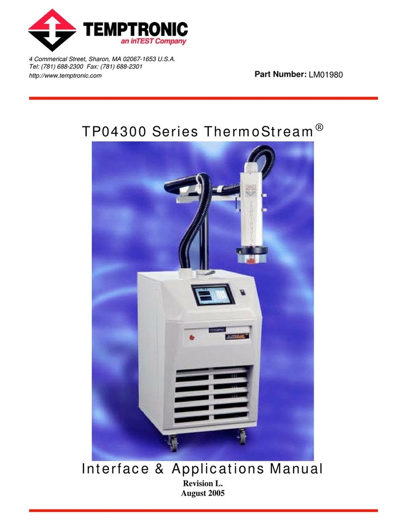
Temptronic ThermoStream TP04100A User manual

-~
ARTISAN
®
~I
TECHNOLOGY
GROUP
Your definitive source
for
quality
pre-owned
equipment.
Artisan Technology
Group
Full-service,
independent
repair
center
with
experienced
engineers
and
technicians
on staff.
We
buy
your
excess,
underutilized,
and
idle
equipment
along
with
credit
for
buybacks
and
trade-ins
.
Custom
engineering
so
your
equipment
works
exactly as
you
specify.
•
Critical
and
expedited
services
•
Leasing
/
Rentals/
Demos
• In
stock/
Ready-to-ship
•
!TAR-certified
secure
asset
solutions
Expert
team
ITrust
guarantee
I
100%
satisfaction
All
tr
ademarks,
br
a
nd
names, a
nd
br
a
nd
s a
pp
earing here
in
are
th
e property of
th
e
ir
r
es
pecti
ve
ow
ner
s.
Find the Temptronic TP04100A-1 at our website: Click HERE

"
TEMPTROMC
CORPORATION
Rev.
B:
04/15/98 TP04100AOperator's Manual
Contents
A.
OPERATOR'S
MANUAL
(English)
Page:
3
Artisan Technology Group - Quality Instrumentation ... Guaranteed | (888) 88-SOURCE | www.artisantg.com

TP04100A
Operator's Manual
Operator
Notes
Rev
B:
0411
5/98
TEMPTRONIC
COPFORATION
Use
this
page
to record any notes.
Use
this
soace for svstemuserlooerator sketches
Page:
4
Artisan Technology Group - Quality Instrumentation ... Guaranteed | (888) 88-SOURCE | www.artisantg.com

Rev
.
B: 04/15/98 TP04100AOperator's Manual
CONTENTS
....................................................................................................................................
1
.
SAFETY PRECAUTIONS
7
.
.........................................................................................................................................
2
POWER ON
AND
OFF
9
...........................................................................................................................................
2.1. LOCALOPERATION
9
2.2.
MAIN
POWER SWITCH
..................................................................................................................................
9
3
.
USER INTERFACE
............................................................................................................................................
11
......................................................................................................................................................
3.1. OVERVIEW
11
3.2. GRAPHICALDISPLAYSCREEN
....................................................................................................................
11
3.3. PROGRAMBUTTONS
......................................................................................................................................
12
3.4. ROTARYENCODER
....................................................................................................................................
12
3.5. 'T'
AND
'K'
DUT
SENSORINPUTS
............................................................................................................
13
3.6. FLOWADJUSTMENT
VALVE
.......................................................................................................................
13
4
.
STARTUPAND SHUTDOWN
....................................................................................................................
15
4.1. STARTUPBYPOWERON
..........................................................................................................................
15
4.2. SYSTEMSTARTUPSCREEN
..........................................................................................................................
16
4.3. TOPMENUSCREEN:
MANUAL
OPERATIONMODE
.......................................................................................
17
4.4. SHUTDOWN
BY
POWEROFF
........................................................................................................................
18
5
.
MANUAL OPERATIONSCREEN
................................................................................................................
19
6
.
MANUAL TEST SETUP SCREEN
...................................................................................................................
23
7
.
SETUP OPTIONSSCREEN
..............................................................................................................................
27
7.1. OVERVIEW
......................................................................................................................................................
27
7.2. SETUPOPTIONS SCREENSELECTIONS
.............................................................................................................
28
Page:
5
Artisan Technology Group - Quality Instrumentation ... Guaranteed | (888) 88-SOURCE | www.artisantg.com

TP04100AOperator's
Manual
Rev
B:
04/15/98
Figures
FIGURE2-1
MAIN
POWERSWITCH
...............................................................................................................................
9
.................................................................................................................................
FIGURE3-1 USERINTERFACE
11
......................................................................................................................
FIGURE
4-
1
SYSTEMSTARTUPSCREEN 16
.................................................................................................................................
FIGURE4-2 TOP
MENU
SCREEN
17
FIGURE
5-
1
MANUALOPERATIONSCREEN
................................................................................................................
19
................................................................................................................
FIGURE
6-
1 MANUALTESTSETUPSCREEN 23
.........................................................................................................................
FIGURE7-1 SETUPOPTIONS SCREEN 27
..........................................................
TABLE3-1 ROTARYENCODEROPERATION:STEPMODE
AND
CHANGEMODE 12
Page:
6
Artisan Technology Group - Quality Instrumentation ... Guaranteed | (888) 88-SOURCE | www.artisantg.com

,A\,
TEMPTRONIC
CORFORATION
Rev. B:
04/15/98
1.
Safety
Precautions
1.1
Scopeof Operator's Manual
TP04100AOperator's
Manual
This manual contains procedures intended for use by operating personnel. Refer to the
TP04100A
Interface
&
Applications Manual
for general and advanced operation, assembly,
interfacing, interconnecting, preventive maintenance and remote operation parameters. The
TP04100A
Service Manual
is for corrective maintenance procedures and is intended for use
by
servicepersonnel.
1.2.
SafetyPrecautionsFor Operating Personnel
WARNING
1:
Operating personnel should perform only the procedures described and
recommended inthis manual. Only qualified servicepersonnelfamiliar with the electrical shock
hazards present inside the equipment should perform disassembly or corrective maintenance of
the equipment.
WARNING
2:
To avoid shock hazard, the equipment must be grounded with an adequate earth
ground in accordancewith local electricalcodes.
WARNING
3:
The locations of potentially dangerousvoltages and other hazards such ashot or
cold surfaces are identified and labeled on the equipment.Be careful to observe these warnings
when installing, operating,maintaining, or servicingthe equipment. Observe all warnings given
inthis manual.
I
I
Symbols:
A.
Caution,
B.
High Voltage,
C.
Hot Surface,
D.
Cold Surface
WARNING
4:
Make sure to
turn
off the
-
(ac) line power and the compressed air to the
TP04100A
System before attempting to access or service the air filters. Do not perform this
serviceunless qualifiedto do so.
Page:
7
Artisan Technology Group - Quality Instrumentation ... Guaranteed | (888) 88-SOURCE | www.artisantg.com

,;2.\-
TEMPTRONIC
v
CORPORATICIN
TP04100AOperator's Manual
Rev
B:
04/15/98
WARNING
5:
Exposed surfaces in and around the output nozzle and thermal cap of the
system can operate at extremelyhot and cold temperatures which are unsafe to touch.
WARNING
6:
The parts contained inside the thermal wand operate at extremely hot and cold
temperatures unsafe to touch. Do not. perform any maintenance inside the thermal wand
assemblyuntil the system is turned off and disconnected. Wait until the thermal wand parts have
reached a safe and stable temperature near ambient.
CAUTION
1:
Some of the packing materials in the TP04100A shipment may be a source for
Electrostatic Discharge (ESD) potential. Do not unpack in the vicinity of
ESD
sensitive
components.
CAUTION
2:
Observe the precautions given on the equipment and within this manual to
prevent damage to the equipment.
CAUTION
3:
Before connecting the TP04100A to its electrical source, check that the
-
(ac)
voltage and frequency to be supplied to the TP04100A are correct for those listed on its data
plate (located on the rear panel of the controller cabinet).
CAUTION
4:
Always hold the thermal wand firmly while positioning or re-positioning the
stand
arm.
CAUTION
5:
Use proper handling and packaging procedures for ESD sensitive circuit boards.
Assume that all circuitboards are the
ESD
sensitivetype.
CAUTION
6:
Unauthorized personnel should not remove from the equipment those panels that
are provided for protection and/or coolingandlor require a tool to remove.
CAUTION
7:
Use suitable Clean Dry Air (CDA) compressed air supply for the TP04100A
system to prevent premature fouling of the filterhegulator assembly provided with the system.
Improper air supply quality can lead to possible damage to system internal operating
components.
CAUTION
8:
Properly install, use and maintain the filterlregulatorassembly provided with the
TP04100A system. Doing so prevents moisture and/or compressor oils from being introduced
into operating componentsofthe system. If left unchecked, this can cause damage to the system
not covered under warranty.
CAUTION
9:
The two thermal runaway Safety sensors (SF1 and SF2), located on the rear
panel, must remain plugged in for normal operation. If SF2 isnot plugged in when the system is
powered On, then an internal fuse must be replaced by qualified service personnel before
normal operation can resume. Only qualified service personnel should disconnect SF1 and/or
SF2.
Page: 8
Artisan Technology Group - Quality Instrumentation ... Guaranteed | (888) 88-SOURCE | www.artisantg.com

TEMPTRONlC
CORPOPATIGN
Rev.
B:
04/15/98 TP04100A
Operator's
Manual
2.
POWER
ON AND
OFF
2.1.
Local Operation
This manual contains instructions for local operation from the front panel of the Model
TP04100A Themostream System. Remote system operation is discussed in the
TP04100A
Interface
&
Applications Manual.
It is advisable to gain familiarity with front panel operation
before attemptingremote operation.
2.2.
Main
Power
Switch
MAIN POWER SWITCH
-\
Figure 2-1 Main Power Switch
Figure 2-1 shows the Main Power Switch which is located on the right hand side of the front
panel of the controller. This switch also serves as the primary
-
(ac) power circuit breaker
(CB1) for
the
system. An IEC
320
connectorforreceivingthe input power cord is located on the
rear panel of the controller.
Before turning the power ON, be sure the line cord is connected at the rear panel of the system
and is connected to the specified
-
(ac) power source and that the source is live. Actuate the
Main Power Switch (CBl) upward to the
I
(ON [up]) position; to turn off power, move the
switchdownwardto the
0
(OFF [down])position.
The Power (onloff) Indicator Lamp becomes illuminated when power is
ON.
See Section 4.1,
Startupby Power ON, on page 15,for system operation.
410P-B-idoc
Page:
9
Artisan Technology Group - Quality Instrumentation ... Guaranteed | (888) 88-SOURCE | www.artisantg.com

TP04
100A
Operator's
Manual
Operator Notes
Use this page to
record
any
notes.
Rev
B:
04/15/98
,/A
TEMPTRONIC
v
CORPORATION
Use this suace for system user/o~eratorsketches
Page: 10
Artisan Technology Group - Quality Instrumentation ... Guaranteed | (888) 88-SOURCE | www.artisantg.com

TEMPTRONE
CORPORATION
Rev.
B:
04/15/98
TP04
100A Operator's
Manual
3.
USER
INTERFACE
r
'T'
&
'K'
SENSORINPUTS
,-
DISPLAY
,
ROTARY
ENCODER
FLOW ADJUSTMENT S
Figure 3-1 User Interface
3.1.
Overview
The TP04100AUser Interface is located on the controllercabinetfront panel and has three main
components (see Figure
3-1,
above): 1) the Graphical Display Screen, 2) five
(5)
Program
Buttons located below the display screen, and
3)
the Rotary Encoder located to the right of the
display screen.
Two additional user interface components are located to the left of the display screen: 1) the
type
'T'
and
'K'
-
Device Under Test (DUT) Sensor Input sockets, and 2) the hot air Flow
-
-
Adjustment valve.
3.2.
Graphical Display Screen
The Graphical Display Screen, located at the center of the controller front panel, is
an
amber
monochrome electroluminescentdisplay, approximately
5.5
inch size in diagonal measurement.
This graphical user interface provides a highly visible readout of operational information. It
allows test engineers, production operators, and non-technical individuals optimum ease of use
with minimum learningtime.
The operational information screens display the following values: active temperature, the
temperature setpoints, soaktimes, ramp rates up and down, number of cycles performed or to be
performed and the controlwindow. Additional screensfacilitateprogramming of Test Setups,
Page: 11
Artisan Technology Group - Quality Instrumentation ... Guaranteed | (888) 88-SOURCE | www.artisantg.com

4L
TEMPTRONIC
v
CORPORATION
TP04100A Operator's Manual Rev
B:
04/15/98
system configuration, define the limits of operation, calibrate the system, and copy test setups.
Menu choices which correspondto various functions are displayed at the bottom of the screen,
abovethe Program Buttons.
3.3.
Program Buttons
There are five
(5)
Program Buttons in a single horizontal line below the Graphical Display
Screen. These five buttons provide easy selection of the menu choices displayed along the
bottom of the display screen. As the various program screens &e selected, the menu choices
automatically change to provide additional menu choices associated with the screen currently
displayed.
3.4.
Rotary Encoder
The Rotary Encoder, to the right of the Display Screen, is used to step through and change
various system parameters and effectively replaces the traditional numeric keypad and enter
key. The Encoder has two modes: Step Mode and Change Mode.
Mode
Step
Change
To Initiate
Is active (initiated)upon
enteringManual Test
Setup or Program Test
Setup screens.
(Parametersare
highlighted).
Press in on the Rotary
Encoder knob once.
(Parameter will blink).
Functions
1.
Rotate Encoderknob
clockwise to cycle
forward through the
parameter choices.
2.
Rotate Encoder knob
counterclockwiseto cycle
backwards throughthe
parameter choices.
1.
Rotate Encoder knob
clockwise to increasethe
parameter value.
2.
Rotate Encoder knob
counterclockwiseto
decreasethe parameter
value.
To Terminate
Press ESC (Escape)
Program Button to exit
the presentprogram
screen.
No Encoder knob press is
required to terminate.
Press Encoder knob once
to acceptthe parameter
change and return to Step
Mode; or, press
ESC
(Escape) Program Button
to cancel the parameter
change and return to Step
Mode.
Table
3-1
Rotary Encoder Operation: StepMode and Change Mode
isgiven in Table
3-1,
above, by rotating the encoder knob in
Step Mode,
the various system
parameters that can be set andlor changedare graphicallyhighlighted,each one
in
successi&. A
Page:
12
Artisan Technology Group - Quality Instrumentation ... Guaranteed | (888) 88-SOURCE | www.artisantg.com

TEMPTRONlC
v
CORPORATION
Rev.
B:
04/15/98 TP04100A Operator's
Manual
I
,
-,
clockwise rotation moves through the parameter choices forward while a counterclockwise
rotationmoves backwards through the choices.
1-8
In
Change Mode,
rotating the encoder knob changes the individual system parameter selected
:
1
for change. A clockwise rotation increases the parameter value while a counterclockwise
i
I
I
rotationdecreasesthe value.
1.
ii
Step Mode
is only available in the Manual Test Setup and Program Test Setup screens, and on
I
the Program Operation screen. StepMode is active (initiated) automaticallyupon entering either
screen. Rotate the encoder knob in either direction until the parameter to be changed is
-I
;
highlighted.Press in onthe encoderknob onceto setthe encoder into
ChangeMode.
!
1
Once in Change Mode the
selected parameter will blink
to signifjr the system is in Change
j
1
,
I
Mode and the parameter selected can now be changed. Rotate the encoder knob to increase or
decreasethe setpoint value to the desired setting.
i
i
j
3
When the
desired setting
has been reached,
press in the encoder knob
a second time to
replace the old parameter value with the new parametervalue.
I
4
I
If the operator does not want to change the selected parameter,
press
the
ESC
Program Button
to
cancel the parameter change,
exitthe Change Mode and return to the StepMode.
I..
1,)
Unlike ESC, if the operator presses the
DONE
Program Button, then the current (highlighted)
Test Setup values are saved to the
"0"
Test Setup (see note on "Default
'0'
Test Setup" at end
1
of "Manual Test Setup Screen:Overview" section,page 23).
1,
I
3.5.
'T'
and
'K'
DUT
SensorInputs
1
1
The
'T'
and 'K' DUT Sensor Inputs are located to the far left of the Graphical Display Screen,
and are used with external type 'T' and type 'K' thermocouple sensors to monitor the actual
I
1
temperature of the device/component being thermally tested. Complete application, operation
and use of DUT sensors is discussed inthe
TP04100A Interface
&
Applications Manual.
i
1
3.6.
Flow Adjustment Valve
I
\
The Flow Adjustment valve is located to the left of the Graphical Display Screen.This valve is
used to vary the output flow from the Thermal Wand of the ThermoStream for the temperatures
1
of
+33.1
OC through
+225
OC, over the range of
2
to
6
Standard Cubic Feet per Minute (SCFM).
I
Complete operation and use of the Flow ~djustmentvalve discussed in-the
TP04100A
i
Interface
&
Applications Manual.
,
Page:
13
Artisan Technology Group - Quality Instrumentation ... Guaranteed | (888) 88-SOURCE | www.artisantg.com

TP04100A Operator's ManuaI
OperatorNotes
Use thispage
to record any
notes.
Rev
B:
0411
5/98
Page:
14
Artisan Technology Group - Quality Instrumentation ... Guaranteed | (888) 88-SOURCE | www.artisantg.com

Rev.
B:
04/15/98 TP04100AOperator's Manual
STARTUPAND SHUTDOWN
4.1.
Startup
by
Power
ON
To startupthe TP04100A System initially or after it has been turned off
1.
Check that the system is connected to the specified compressed air source and the air is
turned on.
2.
Be sure the line cord is connected at the rear panel of the system and is connected to the
specified
-
(ac)power sourceand that the sourceis live.
3.
Actuate the Main Power Switchlocated on the front panel of the controller cabinet upward
to the
I
(ON [up]) position to start operation of the TP04100A. Note that the Power (onloff)
IndicatorLamp should illuminate.
Page: 15
Artisan Technology Group - Quality Instrumentation ... Guaranteed | (888) 88-SOURCE | www.artisantg.com

,
I
A~A
TEMPTRONIC
1
1
v
CGRFORATION
TP04100AOperator's Manual
Rev
B:
04/15/98
i
i
4.2.
System Startup Screen
i
I
Figure 4-1 System Startup Screen
I
The
System Startup Screen
(see Figure 4-1, above) is displayed after the power has been turned
I
ON.
It features the Temptronic Corporation Logo and identifies the TP04100A Thennostream
System.
1
I
The system is ready for operation when the
SystemStartup Screen
is displayed.
I
Press any Program Button to continueto the
TopMenu Screen.
NOTE: If "Auto start in MANUAL OPERATION is set to "ON" in the
ConJigure System
Screen
(see
TP04100AInterface and Applications Manual),
then the system will automatically
start in Manual mode, and display the
Manual Operation Screen
(press ESC to access the
Top
Menu Screen).
I
Page: 16
Artisan Technology Group - Quality Instrumentation ... Guaranteed | (888) 88-SOURCE | www.artisantg.com

,
,<$,,
TEMPTRONIC
,
,
..p
CORFOEATISI~I
Rev.
B:
0411
5/98 TP04
100A
Operator's
Manual
4.3.
TopMenu Screen:Manual OperationMode
Figure 4-2 Top Menu Screen
After pressing
any
button on the
System Startup Screen,
the
Top
Menu Screen
is displayed (see
Figure 4-2, above). This screen allows immediate access to the MANUAL and PROGRAM
OPERATION screens (where temperature testing is performed), and allows access to the
SETUP OPTIONS and CONFIGURE SYSTEM screens.
The FLOW selection allows the operator to toggle the air flow of the Thermal Wand ON and
OFF without temperature control. The first press of the FLOW program button turns the air flow
ON, the second press turns it OFF. This allows the operator to verifjr and/or adjust system air
flow for temperatures of +33.1 "C through +225
"C
by using the Flow Adjustment knob located
to the left of the Graphical Display Screen (see Figure
3-1
User Interface). Complete operation
and use of the Flow Adjustment valve is discussed in the
TP04100A Interface
&
Applications
Manual.
Use the Program Buttons (below the display screen) to select the desired function which
correspondswith each button.
For the purpose of this manual, select the
"MANUAL"
Program Button to continue to the
Manual OperationScreen
to operatein Manual Operation Mode (see Section 5, on page 19).
410P-Bj.doc
Page:
17
Artisan Technology Group - Quality Instrumentation ... Guaranteed | (888) 88-SOURCE | www.artisantg.com

,,%.\
TEMPTRONIC
-
TP04100AOperator's Manual
CORPORATION
Rev
B:
04/15/98
i
1
j
\
I
4.4.
Shutdown
by
Power
OFF
/
i
i
To shutdown the TP04100ASystem after it has been turned on and operated:
3
1. Press the "ESC" Program Button on any program screen to return to the
Top
Menu Screen.
Thismay require one, two or three ESC button presses.
2.
Once at the
Top
Menu Screen, actuate the Main Power Switch downward to the
0
(OFF
[down]) position to
turn
off the TP04100A.-Note that
the
power (ordoff) indicator Iamp
should
turn
off (see Figure 2-1 Main Power Switchon page
9).
NOTE:
When moving
the
TP04100A to a different test location, or when shutting it down for
an extended period,
hun
off and disconnect it from both its
-
(ac) power source and compressed
air supply.
Page:
18
Artisan Technology Group - Quality Instrumentation ... Guaranteed | (888) 88-SOURCE | www.artisantg.com

6@
TEMPTRONC
CORPORATION
Rev.
B:
04/15/98
.
I"
.
.-...
.
.
.
_
. .
TP04100A Operator's Manual
5.
MANUAL
OPERATION
SCREEN
Figure 5-1 Manual Operation Screen
5.1.
Overview
The
Manual Operation Screen
(see Figure 5-1, above) is the first screen displayed in Manual
Mode. The operator can select fiom three programmed temperature controi s&points (HOT,
AMBIENT, COLD), can change the setpoint values, can select "SETUP" to branch to the
Manual Test Setup Screen
(to change setpoint values, changeiselect Test Setup programs, or to
initiaterampicycle routines), and can select ESC to return to the previous program screen.
The DUT Temperature window (see Figure 5-1, upper left) only displays when a DUT sensor
has been selectedand installed (see
TPOllOOA Interface andApplications Manual).
To execute a functionpress the corresponding Program Button.
The function selections at the bottom of the display screen in Figure 5-1 are summarized as
follows.
4
10P-B-i.doc
Page: 19
Artisan Technology Group - Quality Instrumentation ... Guaranteed | (888) 88-SOURCE | www.artisantg.com

TP04100A Operator's
Manual
Rev
B:
04115/98
5.2.
Manual Operation Screen Selections
ESC:
This selection returns the operator to the previous program screen or is used to exit the
ChangeMode and cancel any changesmade tothe selectedparameter value.
HOT:
This selection initiates air flow and starts temperature control at the programmed HOT
setpoint. While the system is controlling temperature at the HOT setpoint, the menu label
located above the Program Button changes from "HOT" to "STOP". By selecting the STOP
button the operator can cease air flow and stop temperaturecontrol at the HOT setpoint.
To change the HOT setpoint temperature use the Rotary Encoder in Change Mode (see
"Rotary Encoder", on page 12 and "Default
"0"
Test Setup," at end of this section). The
permissible temperature range setting for the programmed HOT setpoint is +25"C to +225OC
inclusive. The factory set default value is +125"C.
Alternatively, the operator can select AMBIENT or COLD Program Buttons to change
temperaturecontrolto these setpoints.
AMBIENT:
This selection initiates air flow and starts temperature control at the programmed
AMBIENT setpoint. While the system is controllingtemperature at the AMBIENT setpoint,the
menu label located above the Program Button changes from "AMBIENT" to "STOP". By
selecting the STOP button the operator can cease air flow and stop temperature control at the
AMBIENT setpoint.
To change the AMBIENT setpoint temperature use the Rotary Encoder in Change Mode
(see "Rotary Encoder", on page 12 and "Default "0" Test Setup" at end of this section). The
permissible temperature range setting for the programmed AMBIENT setpoint is +20•‹C to
+30•‹Cinclusiveand the factory set default value is +25"C.
Alternatively, the operator can select HOT or COLD to change temperature control to
these setpoints.
COLD:
This selection initiates air flow and starts temperature control at the programmed
COLD setpoint. While the system is controlling temperature at the COLD setpoint, the menu
label located above the Program Button changes from "COLD" to "STOP". By selecting the
STOPbutton the operator can cease
air
flow and stoptemperature control at the COLD setpoint.
To change the COLD setpointtemperature use the Rotary Encoder in Change Mode (see
"Rotary Encoder", on page
12
and "Default "0" Test Setup" at end of this section). The
permissible temperature range setting for the programmed COLD setpoint is +25"C to -99.9OC
inclusive and the factory set defaultvalue is -10•‹C.
Alternatively,the operator can select either HOT or AMBIENT to change temperature
controlto these setpoints.
Page: 20
4
10P-B-i.doc
Artisan Technology Group - Quality Instrumentation ... Guaranteed | (888) 88-SOURCE | www.artisantg.com

;-\
TEMPTRONIC
CORPORATION
Rev.
B: 0411
5/98
.
..
TP04100AOperator's
ManuaI
SETUP:
This selection accesses the
Manual Test Setup Screen
(see Figure 6-1, on page
23)
where the operator can change setpoint values, changelselect Test Setup programs, and initiate
RarnpICycle routines. Select CYCLE on the
Manual Test Setup Screen
to begin temperature
cycling and return to the
Manual OperationScreen.
While the system is temperature cycling,
the menu label on the
Manual Operation Screen
located above the Program Button changes
fiom "SETUP" to "STOP".
By
selectingthe STOP button the operator can cease air flow and
stoptemperature cycling.
Note:
Default
"0"
Test Setup:
When the setpoint is being changed,the system maintainstemperature
control at the old setpoint value until the new setpoint value is entered by pressing in on the
Encoder knob. Once entered, the system controls at this new setpoint value. Any changes made
to parameter values are automatically saved into the
"0"
(default) Test Setup program. Saved
values are retained even if the system is turned off.
If
the operator does not want to change the
selected parameter, press the ESC Program Button to cancel the parameter change and exit the
Change Mode without saving any new values. To copy setups, see "Copy Test Setups" in the
TP04100AInstallation
&
Applications Manual.
Page:
21
Artisan Technology Group - Quality Instrumentation ... Guaranteed | (888) 88-SOURCE | www.artisantg.com
Other manuals for ThermoStream TP04100A
1
This manual suits for next models
2
Table of contents
Other Temptronic Industrial Equipment manuals