Ten-Haaft COMMAND UNIT Product information sheet
www.ten-haaft.com
KURZBETRIEBSANLEITUNG COMMAND UNIT
SHORT USER MANUAL COMMAND UNITINSTRUCTIONS
MODE D’EMPLOI ABRÉGÉ COMMAND UNIT
COMMAND UNIT


KURZBETRIEBSANLEITUNG COMMAND UNIT
1. Allgemeines
1.1 Sicherheitshinweise
Lesen Sie diese Bedienungs- und Montageanleitung aufmerksam durch, bevor Sie mit der Montage und dem Betrieb beginnen.
Eine fehlerfreie und betriebssichere Funktion kann nur gewährleistet werden, wenn Sie sowohl für die Montage als auch für
den Betrieb diese Anleitung beachten.
2. MONTAGE
2.1 Spannungsversorgung
1. Sorgen Sie für eine ausreichende Spannungsversorgung des Systems
a) Die Anlage benötigt den Anschluss an 12 V / 24 V Bordspannung.
b) Es ist vorgeschrieben, die schwarze Leitung des 3-poligen Spannungsversorgungskabels an die Klemme 15 (geschaltetes
Zündungsplus) des Fahrzeuges anzuschließen. Alternativ können Sie anstelle Klemme 15 auch die Leitung D+ (Genera-
torplus, liegt nur an bei laufendem Motor) verwenden, wenn Ihre Fahrzeugelektrik dies zulässt. In beiden Fällen ist die
zuverlässige Funktion der Sicherheitsschaltung besonders zu überprüfen und sicher zu stellen! Bitte beachten Sie, dass
die Leitung D+ bei manchen Fahrzeugen nicht durch externe Geräte belastet werden darf! Beachten Sie weiterhin, dass
bei manchen Fahrzeugen die Spannung an D+ von der Bordelektrik unter Umständen zeitweise während des
Fahrbetriebes abgeschaltet werden kann. Dies würde die korrekte Funktion der Sicherheitsschaltung verhindern! Prüfen
Sie deshalb besonders, dass im gegebenen Fahrzeug die Spannung an D+ bei laufendem Motor ständig und permanent
stabil anliegt. Verwenden Sie im Zweifelsfall die Leitung K15 (geschaltetes Zündungsplus) zum Anschluss an die
Sicherheitsschaltung.

KURZBETRIEBSANLEITUNG COMMAND UNIT
2. MONTAGE
2.2 Anschlussplan
Fahrtrichtung
Antenna Control
Battery
18
9
17
11
16
14
13
12
8
7
15
5
10
4
3
2
6
1
only with TWIN
(optional)

KURZBETRIEBSANLEITUNG COMMAND UNIT
2. MONTAGE
ANSCHLUSSKENNZEICHNUNG AN DER COMMAND UNIT
Nummer Erklärung
1Außeneinheit
2Montageplatte
3Winkelverschraubung / Dachdurchführung
4Zuleitung von Außeneinheit (schwarzer Schlauch)
5Command Unit
6Bedienteil (falls im Lieferumfang enthalten)
7Koaxialkabel zum Empfangsgerät
8Receiver / TV mit integriertem Receiver
9Schließen Sie hier den Antennenstecker (F-Stecker) des mitgelieferten Steuerkabels zur Auße-
neinheit an. (Steuerkabel und Koaxkabel zur Außeneinheit befinden sich gemeinsam in einer
schwarzen Ummantelung)
10 Sicherung 10A (FKS Mini, rot)
11
Schließen Sie hier das mitgelieferte Stromversorgungskabel an.
ACHTUNG!
Stellen Sie vorher sicher, dass das Stromversorgungskabel am anderen Ende korrekt an das
Stromnetz des Fahrzeuges angeschlossen ist, bei Falschpolung kann die FeatureBox zerstört
werden!
Bordnetzklemme 15: Zündung / ggf. D+ (siehe 2.3) (schwarz)
Bordnetzklemme 30: Bordspannung 12V / 24 V DC (rot)
Bordnetzklemme 31: Fahrzeugmasse / Chassis (Braun)
12 Anschlusskabel (braun - Minuspol)
13 Anschlusskabel (rot - Pluspol)
14 Aufbau-Batterie
15 Anschlusskabel (schwarz - Sicherheitsschaltung)
16 Zündung Klemme 15 von Fahrzeug
17 optionales TWIN Kabel
18 2. Fernsehgerät nur bei TWIN-LNB
KURZBETRIEBSANLEITUNG COMMAND UNIT
3. BEDIENELEMENTE
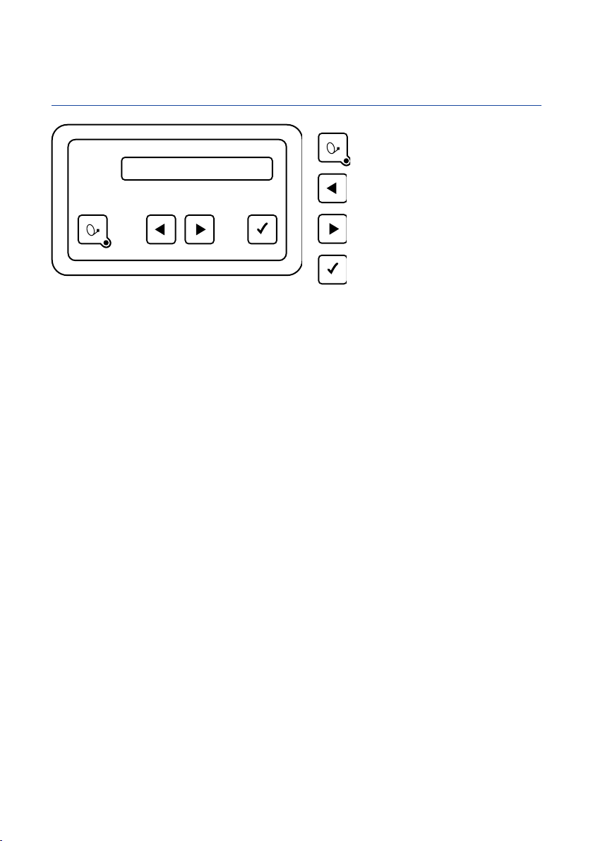
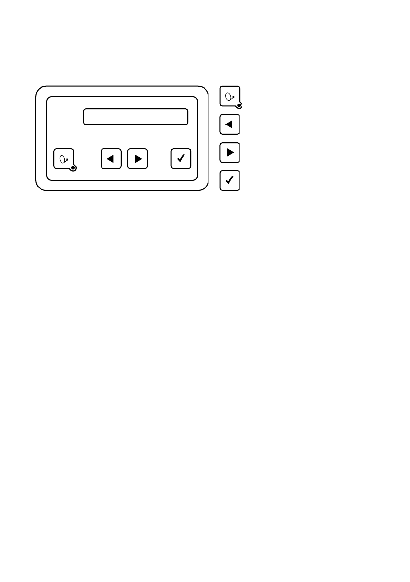
3.1 Bedienteil (falls im Lieferumfang enthalten)
Ein / Aus
Dieses Bedienteil können Sie an einem beliebigen Ort im Fahrzeuginneren anbringen, berücksichtigen Sie aber
bitte, dass es nicht wasserdicht ist. Eventuell müssen Sie noch die Schutzfolie von der Anzeige abziehen.
Im Anzeigefeld des Bedienteiles erhalten Sie diverse Informationen über den aktuellen Betriebszustand Ihrer
Anlage. Um diese Informationen ablesen zu können, empfiehlt es sich, das Bedienteil an einem zugänglichen
Ort zu platzieren.
Da die Anzeige beleuchtet ist, kann sie auch bei Montage an einem sehr dunklen Ort problemlos abgelesen
werden.
Bitte stecken Sie aus Gründen der Betriebssicherheit das Bedienteil nur aus, während Ihre Außeneinheit im
Ruhezustand ist. Dies erkennen Sie daran, dass keinerlei Text in der Anzeige eingeblendet ist.
Ohne ein Bedienteil wird die Anlage vom angeschlossenen Oyster®TV gesteuert. Darüber hinaus ist die Bedie-
nung über die kostenlos verfügbare ten Haaft® App über Smartphone / Tablet möglich.
Menübedienung „zurück“
Menübedienung „vorwärts“
Menübedienung „OK“

KURZBETRIEBSANLEITUNG COMMAND UNIT
3. BEDIENELEMENTE
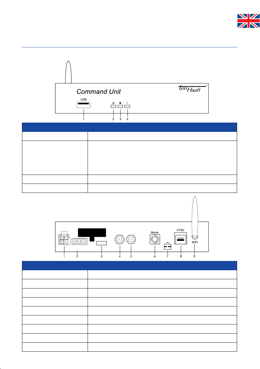
3.2 Command Unit (Vorderseite) (Rückseite)
Die Command Unit steuert entweder über ein verkabeltes Bedienteil, über die App oder über den Oyster®TV die Funktion der
Außeneinheit.
Bus
CI
Ant.
SAT
Battery
10 A
31 30 15
Control1
Antenna
TV
Bedientasten
1. USB
USB-Schnittstelle (für Updates via USB-Stick)
2. Powertaste Hier kann das komplette Antennensystem ein- und ausgeschaltet werden.
Wird diese Taste während der Antennenbewegung gedrückt, erfolgt ein
sofortiger Stop (Not-Stop).
Bei offener, gestoppter Antenne erfolgt durch Drücken dieser Taste das
Einfahren (Parken) und Abschalten (Standby) der Anlage.
3. „Stern“ Taste Reserviert
4. „i“ Taste Diese Taste hat je nach Farbe der LED‘s verschiedene Funktionen.
Anschlüsse
1. Antennensteuerung
4-poliges Steuerkabel Außeneinheit
2. Spannungsversorgung
Zündung/ Klemme 15/ D+ sowie 12 V/ 24V Bordspannungsversorgung
3. Sicherung
10 A (FSK Mini, rot)
4. Ant
SAT In von der Außeneinheit (Antenne)
5. TV
SAT Out zum Receiver/ TV
6. Mode
Drehschalter SAT-Auswahl (Grundstellung 0 = Automatikmodus)
7. CI-Bus
Optionaler Steuerungseingang
8. CTRL
Anschluss Bedienteil (falls im Lieferumfang enthalten)
9. WiFi
WLAN-Antenne

KURZBETRIEBSANLEITUNG COMMAND UNIT
3.3 Warnton Command Unit
Die Command Unit erzeugt einen Warnton, wenn der Fahrzeugmotor gestartet wird und die Antenne sich nicht in ihrer endgül-
tigen Parkposition befindet.
Wird der Fahrzeugmotor bei offener Antennenanlage gestartet, beginnt die Antenne umgehend mit dem Einfahren. Dies kann
bis zu 40 Sekunden dauern. Ein kurzer Signalton ertönt und weist darauf hin, dass die Antenne noch vollständig einfahren muss,
bevor das Fahrzeug bewegt werden darf.
Wenn das Einfahren der Antenne aufgrund einer Störung nicht vollständig möglich ist ertönt ein permanenter Warn-
ton. Dieser Warnton verstummt erst, wenn die Anlage vollständig eingefahren ist oder die Zündung des Fahrzeugs
(Klemme 15) abgeschaltet wird.
4. ANHANG
4.1 Hinweise zum Umweltschutz
Altfahrzeugverordnung - ELV
Das Antennen-System ist als Zubehör zur Verwendung auf Kraftfahrzeugen zertifiziert und vorgesehen. Die Entsorgung kann
demgemäß im Rahmen der Altfahrzeug-Verordnung (Europäische Altfahrzeugrichtlinie ELV, 2000/53/EG; für Deutschland:
AltfahrzeugV) zusammen mit dem Kraftfahrzeug erfolgen. Das Antennen-System enthält keine der gemäß Richtlinie als
umweltschädlich eingestuften Stoffe.
Wir wünschen Ihnen viel Freude mit Ihrer SAT-Anlage
Ihr ten Haaft Team
ten Haaft GmbH
Neureutstraße 9
75210 Keltern
Deutschland
Tel.: +49 (0) 7231 / 58588-0
Fax: +49 (0) 7231 / 58588-119
Homepage: www.ten-haaft.com
KURZBETRIEBSANLEITUNG COMMAND UNIT
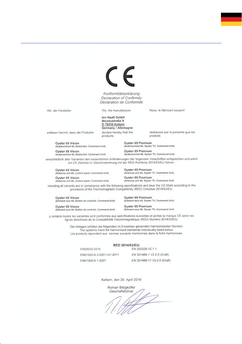
4.2 Konformitätserklärung CE

KURZBETRIEBSANLEITUNG COMMAND UNIT
5. PLATZHALTERSKIZZE FÜR DIE COMMAND UNIT

KURZBETRIEBSANLEITUNG COMMAND UNIT
5. PLATZHALTERSKIZZE FÜR DIE COMMAND UNIT


SHORT USER MANUAL COMMAND UNIT
1. GENERAL INFORMATION
1.1 Safety precautions
Read the operating manual and installation instructions carefully before installing the system. Correct and safe operation of the
system can only be ensured if both the installation instructions and the operating instructions are observed.
2. MONTAGE
2.1 Power supply
a) The system must be connected to the 12/24-V onboard electric system.
b) Be sure to connect the black cable of the 3-line power supply harness to terminal 15 (switched ignition supply) of the
vehicle. Alternatively, you can also connect the black cable to line D+ (generator positive terminal, only live when
engine is running) instead of terminal 15, your vehicle’s electric system permitting. In both cases, be sure to make a
function check! In both cases, both you must double-check that the safety circuit functions reliably! Keep in mind that
in some vehicles it is not permissible to connect additional power consumers to the D+ line! Note that in some vehicles,
the voltage on the D+ line may be switched off temporarily by the vehicle’s electric system while driving. This would
prevent the safety circuit from functioning properly! When deciding for this type of connection, make sure that the
voltage on the D+ line is present at all times and stable while the engine is running. When in doubt, connect the safety
circuit to a line supplied via terminal 15 (via the ignition lock).

SHORT USER MANUAL COMMAND UNIT
2. INSTALLATION
2.2 Connections
Direction of travel
Antenna Control
Battery
18
9
17
11
16
14
13
12
8
7
15
5
10
4
3
2
6
1
only with TWIN
(optional)
SHORT USER MANUAL COMMAND UNIT
2. INSTALLATION
Connections at the Command unit
Number Explanation
1Antenna unit
2Mounting plate
3Elbow fitting / roof feed-through
4Satellite harness from exterior unit (black hose)
5Command Unit
6Control panel (if included in supply)
7Coaxial cable to receiver
8Receiver / TV with integrated receiver
9Connect here the antenna plug (F plug) of the provided control cable to the external unit.
(Control cable and coax cable to the external unit are together in a black sheath.)
10 Fuse
11
Connect the power-supply cable provided here.
CAUTION!
Ensure that the other end of the power-supply cable is correctly connected to the onboard
electric system. If polarity is reversed, the FeatureBox may be destroyed!
Onboard system terminal 15: Ignition / D+ (optional, see 2.3) (black)
Onboard system terminal 30: Onboard system voltage 12/24V DC (red)
Onboard system terminal 31: Vehicle ground / chassis (brown)
12 Connecting cable (brown – battery negative)
13 Connecting cable (red – battery positive)
14 Body battery Coaxial cable to receiver
15 Connecting cable (black – safety circuit)
16 Ignition-switched terminal 15 of vehicle
17 optional TWIN cable
18 2. TV set only with TWIN-LNB
SHORT USER MANUAL COMMAND UNIT
3. CONTROL ELEMENTS
3.1 Control panel (if included in supply)
On / Off
You may choose any location you like to install the control panel, but please bear in mind that it is not waterproof. You may still
need to remove the protective film from the display.
The display of the control panel will show the various operating modes of the system. We recommend you to install the control
panel in a location where the display is clearly visible.
The display is illuminated, so it is not a problem if it is installed in a very dark location.
To ensure safe and reliable operation of the system, please make sure the external unit is in rest mode before disconnecting the
control panel. Check that no text is shown in the display – this is an indication that the system is in rest mode.
Without control panel, the system is controlled by the Oyster®TV connected to it. You can also control the system using your
mobile device or tablet with the free ten Haaft® app.
Menu command "forward"
Menu command "back"
Menu command "OK"
SHORT USER MANUAL COMMAND UNIT
3. CONTROL ELEMENTS
3.2 Command Unit (front face) (rear face)
The Command Unit controls either the functions of the external unit via a hard-wired control panel, via the app or via the
Oyster® TV.
Bus
CI
Ant.
SAT
Battery
10 A
31 30 15
Control1
Antenna
TV
Control panel
1. USB
USB port (for updates via USB stick)
2. Power button This button switches the entire antenna system on and off. If you press
this button while the antenna is in motion, it will stop immediately
(emergency stop).
When the antenna is open and stopped, pressing this key will cause the
system to retract (park) and shut down (standby).
3. „Star“ button reserved
4. „i“ button This button has various functions that are indicated by the colour of the LED.
Inputs/outputs
1. antenna control
4-pin plug contracable external unit
2. Powersuply
Ignition/ terminal 15/ D+ and 12V/ 24V powersupply
3. Fuse
10 A (FKS-Mini, red)
4. Ant
SAT IN from external unit (Antenna)
5. TV set
SAT OUT to Receiver/ TV
6. Mode
Rotary switch for SAT mode (default setting 0 = automatic mode)
7. CI-Bus
Optional control input
8. CTRL
Control panel (if included in supply)
9. WiFi
WiFi antenna

SHORT USER MANUAL COMMAND UNIT
3.3 Warning Tone Command Unit
The Command Unit will sound a warning tone if the vehicle engine is started before the antenna is fully retracted and in its
‘Park’ position.
If the vehicle engine is started whilst the antenna is still open, the antenna will automatically retract. This can take up to 40
seconds. A short signal tone will indicate that the antenna must retract fully before the vehicle can be moved.
If the antenna, for whatever reason, cannot be fully retracted, a constant warning tone will be heard. This warning tone will only
stop once the antenna is either fully retracted or the vehicles ignition (Terminal 15) is turned off.
4. APPENDIX
4.1 Notes on the protection of the environment
EC End-of-Life Vehicle Directive
The antenna system is certified and intended for use as an accessory of a motor vehicle. The system may be
disposed of together with the vehicle in accordance with the End-of-Life Vehicle Directive ELV, 2000/53/EC.
The antenna system does not contain any materials rated as hazardous to the environment according to the
directive.
We hope your satellite system brings you lots of joyful entertainment hours.
Your ten Haaft team
ten Haaft GmbH
Neureutstraße 9
75210 Keltern
Germany
Tel.: +49 (0) 7231 / 58588-0
Fax: +49 (0) 7231 / 58588-119
Homepage: www.ten-haaft.com

SHORT USER MANUAL COMMAND UNIT
4.2 Declaration of conformity CE

SHORT USER MANUAL COMMAND UNIT
5. INSTALLATION SPACE REQUIRED FOR THE COMMAND UNIT
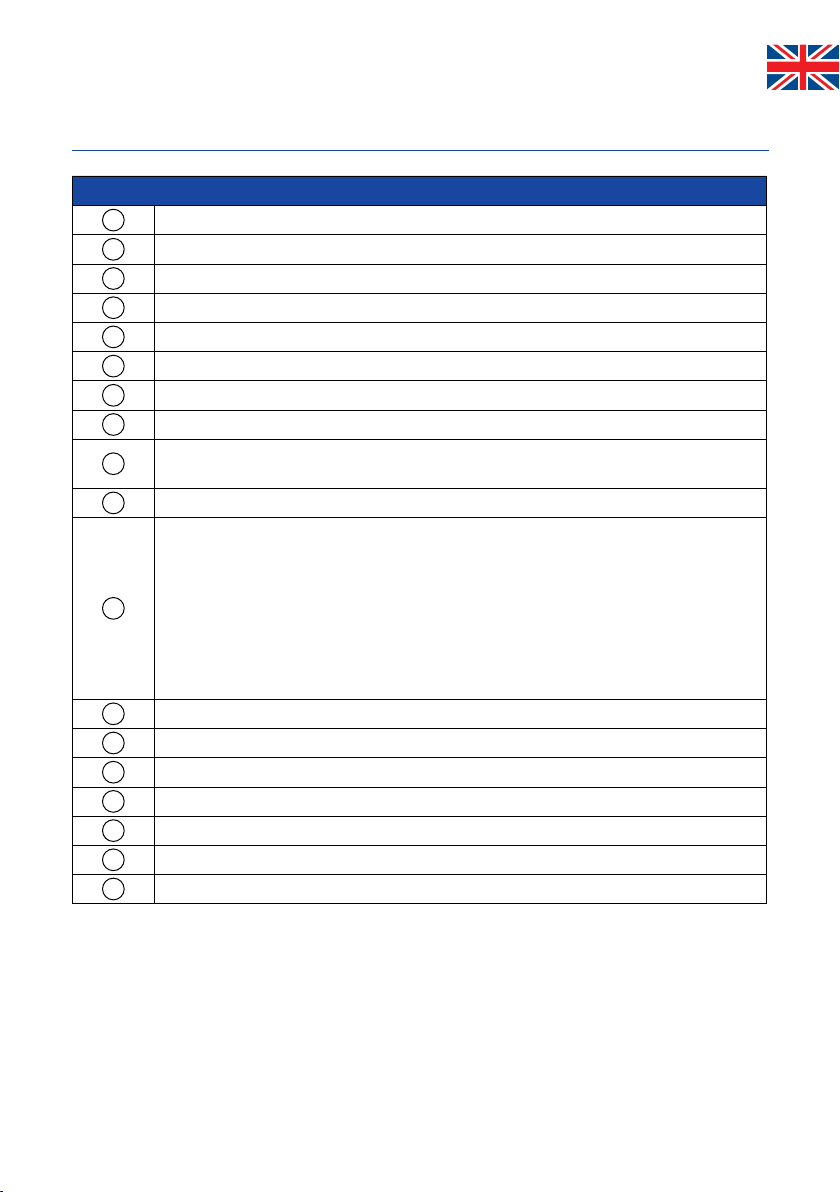
Table of contents
Languages:
Other Ten-Haaft Receiver manuals


