Ten-Tronics A-1163P User manual

1
Volume Control with Impedance Matching Manual A-1163P
The A-1163P Volume Control is a wall-mount stereo
speaker-level volume control with impedance
matching. It connects between the speaker outputs
of an amplifier or receiver and a pair of speakers.
The A-1163P is matching the minimum output
impedance of the amplifier or receiver, in addition to
adjusting volume. It eliminates the need for a
speaker selector or impedance matching equipment.
IMPORTANT: Before installation, review the
manuals included with each component in your
system. If you are unsure of any of the installation
procedures described herein or elsewhere, consult a
professional electronics installer.
A-1163P FEATURES
1. Rotary control of volume level and speaker on/off
2. Impedance matching
3. Fits standard faceplates
SPECIFICATIONS
Power Handling:
…………..…300 watts max; 100watts RMS continuous
Input Impedance:
……… Config. to 1x, 2x, 4x, or 8x impedance matching
Quick Connect Terminals:
………...…………………….Accept up to 12-gauge wire
Attenuation:
……….....12 steps including off; total attenuation 54 dB
Frequency Response:
……………..…20 Hz ~ 20 kHz, +/- 2 dB at rated power
Mounting:
……………...…….Fits most single-gang junction boxes
Dimensions:
………………...………………. 42W x 103H x 103D mm
INSTRUCTIONS
CONSIDERATIONS
1. Make sure that your amplifier has adequate
wattage for the number of speakers. Watts per
channel divided by the number of pairs should
equal or exceed the individual speaker’s minimum
wattage requirements.
2. You must use one A-1163P volume control for
each pair of speakers.
3. Every switch setting must be set on the same
setting throughout the system.
4. A minimum speaker load of 4 ohms can be
connected to the output of each A-1163P volume
control.
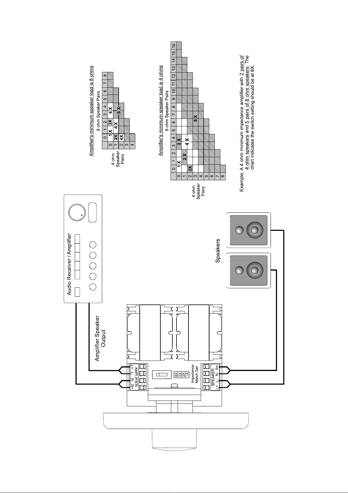
SET THE CORRECT SWITCH POSITION FOR
IMPEDANCE MATCHING
Important: A minimum speaker load of 4 ohms can
be connected to the output of each A-1163P volume
control.
The switch must be set in a position that correctly
multiplies the impedance of the system to a level
that is equal to or greater than the impedance of the
amp.
1. Determine the amplifier's minimum impedance (as
listed in its owner’s manual or on its back panel).
2. Choose the correct impedance-matching chart (8
ohm or 4 ohm) shown on the 3rd page. If your
amplifier is 6-ohm, use the 8-ohm chart. Count
pairs of 6-ohm speakers as 4-ohm pairs.
3. Determine the total number of 4-ohm pairs of
speakers (rows on charts). Count pairs of 6-ohm
speakers as 4-ohm pairs.
4. Determine the total number of 8-ohm pairs of
speakers (columns on charts)
5. See the switches on all of the controls (A-1163P)
to the same position (1x, 2x, 4x, or 8x) as shown
in the illustrations on the 3rd page.
WIRING INSTRUCTIONS
Type of Speaker Wire
For most applications, we recommend you use
16 or 18 gauge, stranded copper speaker wire
for the A-1163P speaker connections. For wiring
runs longer than 100 feet, 12 gauge wire is
recommended. Using speaker wire larger than
12 gauge for A-1163P Volume Controls is not
recommended as the wire may not fit into the
connectors.
Amplifier & Speaker Connections
1. Connect the leads from the amplifier’s speaker
outputs to the connector labeled INPUT on the
A-1163P. Make sure to maintain polarity (+, –) as
well as channel identification (Left, Right).
CAUTION: Do not reverse the input and output
connections!!
NOTE: A majority of receivers are designed to
operate at a rating of 8 ohms. On receivers that offer
A and B speaker outputs, the A and B connections
share the same amplifier. It is important to note, due
to the way many receivers are wired, that when
using impedance matching devices, such as
A-1163P volume controls, it is recommended to wire
all speakers to the A output.
2. Connect the OUTPUT on each A-1163P volume
control to a pair of speakers.

2
INSTALLATION
The total mounting depth from the wallplate/faceplate to the back of the A-1163P is 3.2".
You must use a minimum of a standard light switch plaster ring (P-Ring) or a standard
20 cu. in. (or larger) electrical box. Suitable P-Rings and electrical boxes are available
from your local electrical supply company. Using the P-Ring during new construction is
best because it gives you unobstructed access to the full depth of the wall (some
building codes require that wall devices be enclosed in electrical boxes; check your
local building code).
Do not install the A-1163P into electrical boxes with 110V devices. Speaker wires can
act as an “antenna” for electrical noise.
Locating speaker wires too close to a light switch or dimmer switch may cause a
“humming” or “buzzing” sound to be heard through the speakers. If you must locate the
Volume Control near electrical devices, install it in a separate metal electrical box,
ground the box to the electrical system ground, and route the speaker wires several feet
away from the electrical wiring.
Install the completed A-1163P assembly in the electrical box. Insert carefully to avoid
excessive strain on wire connections. Taking the time to feed excess wire out the back
of the electrical box will help you with the final mounting.
OPERATION
1. Make sure your audio receiver is OFF and set its volume all the way down.
2. Set the A-1163P volume to maximum (fully clockwise).
3. Make certain the receiver volume is all the way down. Then turn on the receiver and
select a music source, such as tuner or CD player.
4. Slowly turn up the receiver volume and set it to a comfortable (not maximum) listening
level. Be careful not to overdrive your receiver. If the sound becomes muddy or
distorted, you have reached the limit of your receiver’s volume capability and should
quickly reduce the volume to avoid damaging your speakers.
NOTE: 12 o’clock (50%) on most receivers is full volume. A receiver that is being
driven beyond its potential will produce DC voltage (clipping) which will not pass
through a transformer, resulting in improper signal transfer and possible amplifier
shutdown or damage.
5. Use the A-1163P to adjust the speaker volume to the desired listening level.
6. You can turn off the speakers in each room by turning the knob on the A-1163P fully
counter-clockwise.
3


