Ten47 Powerline PSF-E-GN-T4-FP User manual

Switches Plus Components Pty Ltd
242 Governor Road, Braeside, VIC, 3195
Phone: 03 8587 3200
Email: [email protected]
1
Powerline Connectors
Quality Checking
Objective:
This procedure identies the recommended method of terminating a range of power cables to our Set Screw (or Pinch Screw) contacts
and our Crimp Contacts. It sets out in clear, easy to read and understand, step by step instructions, the preparation of the cable, the
termination method and the areas which need to be considered to ensure a correct and successful termination.
Safety:
In all assemblies where metal items are being assembled and in particular where cables are being processed, handling is very important.
Tooling such as cutters and sharp bladed knives must be handled with care. When conductor wires are cut it is recommended that Safety
Glasses should be worn. It is the operators responsibility to follow every safety instruction and if they are unsure on any aspect of the
assembly / termination, to seek information from a qualied person.
Initial Quality Checks:
Prior to use, all contacts and insulators should be checked as follows:
(a) Ensure the band on the Male Contact is not broken or twisted and is positioned correctly in the groove.
(b) Ensure the insulated nose of the Male Contact is not broken, cracked or discoloured.
(c) Ensure the Insulated nose of the Female Contact is not broken, cracked or discoloured and can be fully recessed into the
metal body of the contact.
(d) The 2 set screws supplied with the Set Screw contacts are a special dome fronted design. They are 16mm long and have a
5mm A/F drive. Other set screws are not recommended as they may cause damage to the contact / conductor termination.
(e) Check for any signs of rust on the electrical contact and component parts.
(f) Check for any cracks or breaks on the connector insulator.
(g) Ensure the clip retainers inside each insulator are not discoloured or broken.
Selection of Cable Gland.
1) Ensure the cable gland has a sealing o-ring and internal compression sleeve tted.
2) The cable gland must be positioned onto the cable prior to tting the terminated
contact into the connector insulator.
3) To ensure environmental sealing between the cable and connector, careful
consideration is required to select the correct gland for the external cable
diameter being used.
4) We have 4 standard cable glands available as follows:
M40S. External cable diameters from 15mm to 20mm.
M40M. External cable diameters from 20mm to 25mm.
M40OS. External cable diameters from 25mm to 32mm.
M50. External cable diameters from 32mm to 37mm.
5) Tighten the cable glands to a torque of 13Nm to ensure correct environmental
sealing is obtained.
The Crimp Contact:
Below is a picture of both the Male and Female crimp contacts
as supplied. These can be supplied for termination to 185mm²,
240mm² and 300mm² stranded conductor applications. If
clarication on size is required, please consult the factory.
The Set Screw Contact:
Below is a picture of the Male and Female contacts as supplied.
Switches Plus Components Pty Ltd
242 Governor Road, Braeside, VIC, 3195
Phone: 03 8587 3200
Email: [email protected]
2
Powerline Connectors
Cable Selection and Preparation:
Most power cables consist of multi-stranded conductors and double insulated Jackets. Our contacts are not designed to terminate onto
solid conductors.
Our Set Screw Contact range is from 25mm² to 120 / 150mm². (The internal dimensions of the set screw contact was originally designed
for 120mm² cables, but depending on the class of copper conductors used, it is sometimes possible to t 150mm² cables) Our Crimp
Contacts range includes 185mm², 240mm² and 300mm².
The selection of the conductor size and jacket insulation size / type is a customer decision but must conform to the current carrying
capability of the contact and the connector into which the contact is tted.
The cable is to be prepared and terminated as per Table 1:
Cable Size Up to 150mm² 185mm² Class 5 240mm² Class 5 300mm² Class 5
Insulation Strip (dim C) 33mm 40mm 40mm 40mm
Recommended Number of Crimps N/A (set screw) 2 3 3
Hand Operated Crimp Tool N/A HT131-C HT131-C HT131-C
Cordless Hydraulic Crimp Tool N/A B131-C B131-C B131-C
Crimp Die Set N/A T185-CF T240-CF T300-CF
Contact Removal Tool REM-185 REM-240 REM-240 REM-300M50
It is recommended to apply multiple crimp
compressions in accordance with the
above table to obtain optimum mechanical
and electrical performance. The correct
sequence of compressions is as shown.
When correctly terminated, the Electrical
and Mechanical performance of the Crimp
will be in accordance with IEC61238-1.
Due to the numerous cable types available,
it is recommended to contact us to conrm
cable & crimp suitability if unsure.
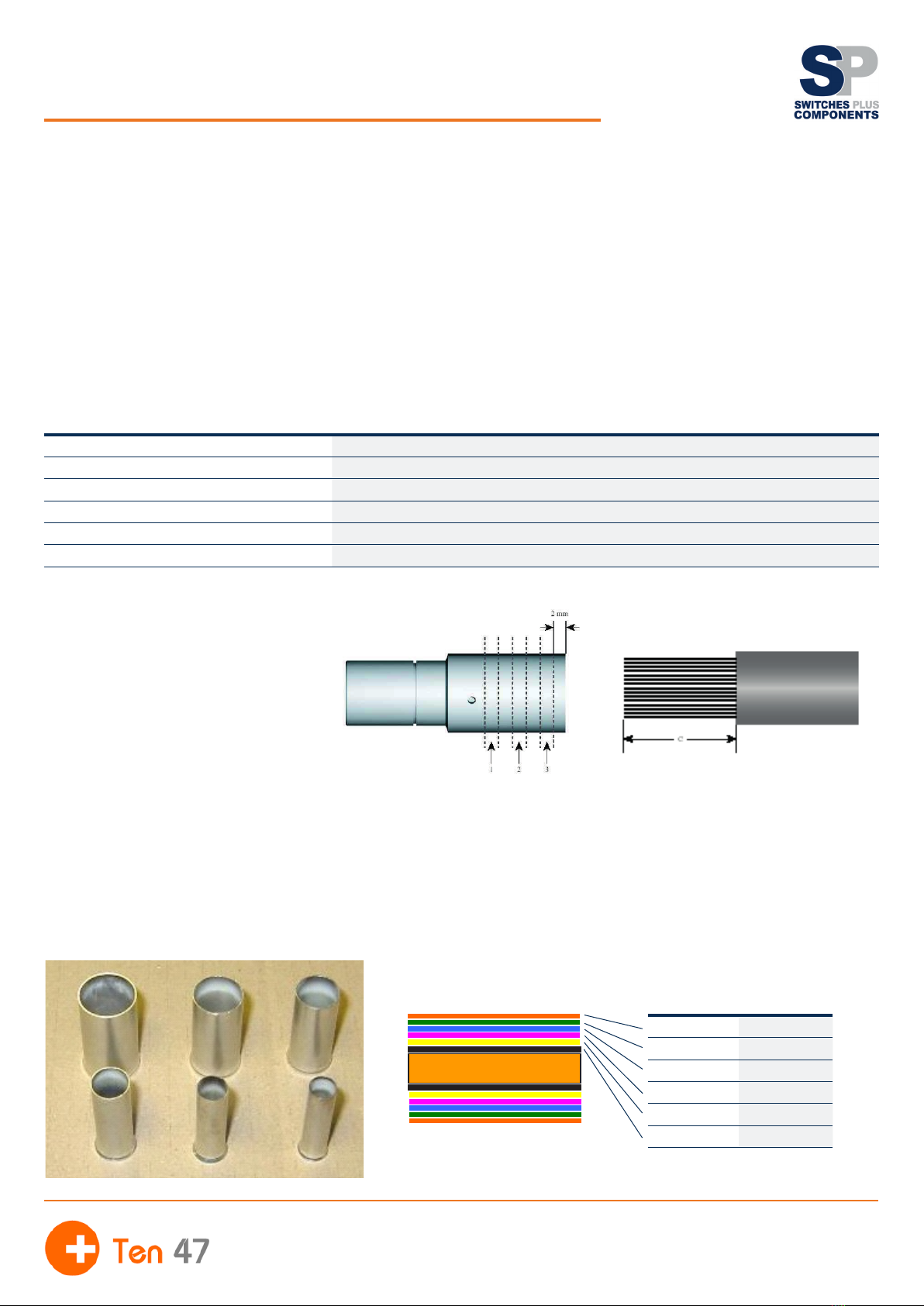
Cable Termination to Contact:
The Set Screw contact’s maximum capacity is a 150mm² stranded conductor. Smaller conductors can be accommodated and these
normally fall into the following sizes 25mm², 35mm², 50mm², 70mm², 95mm² and 120mm². In all applications, a crimp sleeve (or a
combination of crimp sleeves) must be tted. The sleeves main purpose is to contain the stranded wires and prevent breakage or damage.
The contact entry hole is designed for the 120mm² sleeve, but if a smaller size conductor is being used, then a series of telescopic
reducing sleeves must be used to maintain the best electrical contact. These compression sleeves slide into each other, with the smallest
being appropriate to the conductor size being used. See the following sketch for a typical example.
Copper Conductor Strands
Cable Preparation
Part Number Type/Size
PR000120 CS120
PR000095 CS95
PR000070 CS70
PR000050 CS50
PR000035 CS35
PR000025 CS25

Switches Plus Components Pty Ltd
242 Governor Road, Braeside, VIC, 3195
Phone: 03 8587 3200
Email: [email protected]
3
Powerline Connectors
Termination to Set Screw contacts:
1) Select the cable and strip the Insulation / Jacket in accordance with Table 1.
2) Slide Contact Removal Collar onto cable.
3) Select the appropriate compression sleeves and t onto the stripped cable end.
4) Fully slide the sleeves and stripped cable into the rear of the contact and position collar correctly.
5) Using an M5 A/F Allen key, tighten the 2 set screws by hand. Tighten the set screw closest to the cable insulation 1st.
6) Fully tighten both set screws to a torque of 12Nm.
Termination to Crimp contacts:
7) Select the cable and strip the Insulation / Jacket in accordance with Table 1.
8) Select the appropriate crimp dies and tool in accordance with Table 1.
9) Fully slide the stripped cable into the rear of contact and ensure the copper strands are visible through the contact
inspection hole.
10) Crimp in accordance with Table 1.
11) After crimping, ensure any sharp edges are dressed off the contact.
Fitting the contact into the Connector Insulator:
1) From the rear of the insulator, ensure that both the White and Silver contact retaining clips are in place and in the correct
position as shown below. These clips should not interfere with the cut out section within the Insulator. The clips can be rotated
/ moved slightly by nger to the correct position as shown below.
2) Holding the contact rmly, align the gold coloured bar on the contact with the cut-out in the insulator and push the contact
into the insulator.
3) If correctly aligned, the contact will engage with the clip retention mechanism and an audible click will be heard indicating
the contact is correctly secured.
4) A nal check is to push against the front insulated nose of the contact. The contact should remain secure and not slide back.
Removal of the contact from the Connector Insulator:
1) Select the correct removal tool from Table 1 and position the 2 halves around the terminated contact and / or cable.
2) Push the tool into the rear of the insulator until the nose of the tool engages with the clip retention mechanism.
3) Push on the insulated nose of the contact whilst at the same time pulling the contact and / or cable.
4) The contact can then be withdrawn from the insulator.
5) Note: Our Powerline Insulators have a 360º sealing o-ring located within their front face. Some physical resistance will be
felt as the contact is being inserted or removed from the Insulator. Prior to assembly, a thin lm of Silicone Grease applied to
the o-ring will extend its life and ease insertion and removal of the contact from the Insulator.
Termination and Assembly
Note: Our Powerline Insulators have a 360º sealing o-ring located
within their front face. Some physical resistance will be felt as the
contact is being inserted or removed from the Insulator. Prior to
assembly, a thin lm of Silicone Grease applied to the o-ring will
extend its life and ease insertion and removal of the contact from the
Insulator.

Switches Plus Components Pty Ltd
242 Governor Road, Braeside, VIC, 3195
Phone: 03 8587 3200
Email: [email protected]
4
Powerline Connectors
In conclusion and this can be used as a check list for build or maintenance, the following points need to be considered:
Contact:
1) Have the contacts been checked for any signs of damage?
2) Have the appropriate reduction sleeves been supplied?
3) Is the correct tooling available for the set screw and crimp contact terminations?
4) On the maintenance schedule, does the contact show sign of rust due to water ingress?
Cable Termination:
1) Has the cable jacket been removed to the correct strip length?
2) Have the appropriate reduction sleeves been tted?
3) Has the correct cable gland been selected?
4) Is the contact secure within the insulator?
5) Is the contact removal tool available?
6) On the maintenance schedule, has the cable jacket been damaged and the copper conductor corroded?
7) On the maintenance schedule, have the internal clip retainers been checked for corrosion and do they still operate correctly?
Connector and Gland Termination:
1) On the maintenance schedule, does the connector insulator show any signs of damage (cracks, excessive nose wear)?
2) Is the sealing o-ring on the male insulator split or cracked?
3) Are the sealing internal o-rings in place on both the male and female insulators?
4) Is the secondary locking mechanism working correctly?
5) Has the cable gland seal compressed rmly around the cable jacket?
IF IN DOUBT ABOUT ANY PART OF THIS PROCEDURE, PLEASE CONTACT OUR SALES OFFCE.
Checklist
Colour 400Amp Panel Source 400Amp Panel Drain 120mm² Line Source 120mm² Line Drain
Green PSF-E-GN-T4-FP PIF-E-GN-T4-FP CCF-E-GN-S120-M-FP CPF-E-GN-S120-M-FP
Black PSF-N-BK-T4-FP PIF-N-BK-T4-FP CCF-N-BK-S120-M-FP CPF-N-BK-S120-M-FP
Red PSF-1-R-T4-FP PIF-1-R-T4-FP CCF-1-R-S120-M-FP CPF-1-R-S120-M-FP
White PSF-2-WH-T4-FP PIF-2-WH-T4-FP CCF-2-WH-S120-M-FP CPF-2-WH-S120-M-FP
Blue PSF-3-BU-T4-FP PIF-3-BU-T4-FP CCF-3-BU-S120-M-FP CPF-3-BU-S120-M-FP
POWERLINE Industry standard single pole power connectors are designed
to provide safe, reliable and quick connection of Cable to Cable or Cable to
Equipment in Electrical power distribution systems. Compatible with brands
such as the original Litton Veam series, our connectors feature a unique clip
contact removal system, improved nger proong, easier mating and thicker
wall sections on the mouldings.
Applications include:
• Event Power distribution
• Temporary Generators
• Loadbanks
• Emergency Power systems
• Military
• Traction
This manual suits for next models
19


