TenaControls NX-01-1K KIT Quick start guide

TenaControls LLC
Milford, M@ 01757 U.S.@.
www.Ten^Controls.com
TenaControls Brings Models to Life
© Copyright 018 Ten^Controls LLC
P^ge 1
-
--
-
W
WW
W
IRING
IRING IRING
IRING
D
DD
D
IAGRAM
IAGRAMIAGRAM
IAGRAM
&
&&
&
I
II
I
NSTRUCTIONS
NSTRUCTIONSNSTRUCTIONS
NSTRUCTIONS
-
--
-
W
WW
WIRING
IRING IRING
IRING D
DD
DIAGRAM
IAGRAM IAGRAM
IAGRAM OF
OFOF
OF THE
THE THE
THE NX
NXNX
NX-
--
-01
0101
01-
--
-1K
1K1K
1K
K
KK
KIT
ITIT
IT
F
FF
FOR
OR OR
OR T
TT
THE
HE HE
HE
1:1000
1:10001:1000
1:1000
S
SS
SCALE
CALE CALE
CALE E
EE
ENTERPRISE
NTERPRISE NTERPRISE
NTERPRISE NX
NXNX
NX-
--
-01
0101
01
I
II
ITEMS
TEMS TEMS
TEMS Y
YY
YOU
OU OU
OU W
WW
WILL
ILL ILL
ILL N
NN
NEED
EEDEED
EED:
::
:
Soldering Iron
Solder
Cutter
Wire Stripper
Refer to the Master Wiring Diagram on page 8 for all external connections to
the circuit board.
Here is the link to the Instructional ideo:
Here is the link to the Instructional ideo:Here is the link to the Instructional ideo:
Here is the link to the Instructional ideo:
https://www.youtube.com/watch?v=zHrNIi8qKQ4
https://www.youtube.com/watch?v=zHrNIi8qKQ4https://www.youtube.com/watch?v=zHrNIi8qKQ4
https://www.youtube.com/watch?v=zHrNIi8qKQ4
***A digital version of this Manual can be requested via email: ***
***A digital version of this Manual can be requested via email: ******A digital version of this Manual can be requested via email: ***
***A digital version of this Manual can be requested via email: ***

TenaControls LLC
Milford, M@ 01757 U.S.@.
www.Ten^Controls.com
TenaControls Brings Models to Life
© Copyright 018 Ten^Controls LLC
P^ge
H
HH
How to d st ngu sh wh ch s de s the Cathode and wh ch s de s
ow to d st ngu sh wh ch s de s the Cathode and wh ch s de s ow to d st ngu sh wh ch s de s the Cathode and wh ch s de s
ow to d st ngu sh wh ch s de s the Cathode and wh ch s de s
the Anode on an LED:
the Anode on an LED:the Anode on an LED:
the Anode on an LED:
**Note:
**Note:**Note:
**Note: When using the shrink tubing, you need to only slide the shrink tubing over one
leg of the LED to keep it from shorting against the other leg. Then use a heat gun or
flame from a lighter to heat the shrink tubing until it shrinks around the wire connected
to one of the LED legs. Recommendation: shrink tube the positive side of the LED.
Now, connect the 9 volt battery clip, red to one side of the on/off switch, the other side
of switch to Red wire from board, then the Black from battery clip to Black wire from the
board. See Master Wiring Diagram on page 8.

TenaControls LLC
Milford, M@ 01757 U.S.@.
www.Ten^Controls.com
TenaControls Brings Models to Life
© Copyright 018 Ten^Controls LLC
P^ge 3
-
--
-
I
II
I
NSTRUCTIONS
NSTRUCTIONS NSTRUCTIONS
NSTRUCTIONS
-
--
-
S
SS
STROB
TROBTROB
TROBE
E E
E S
SS
SIDE
IDEIDE
IDE
(R
EFERENCE THE
M
ASTER
W
IRING
D
IAGRAM ON
P
AGE
8)
1. Two
TwoTwo
Two White
White White
White LED’s:
LED’s: LED’s:
LED’s: LED
LED LED
LED2
22
2
-
--
-
3mm
3mm3mm
3mm and
and and
and LED
LEDLED
LED6
66
6
-
--
- 3mm
3mm 3mm
3mm
The Two Anodes (+) of the Strobe LED’s, LED2 and LED6 will terminate to White
wire from JST Micro Connector on the pc board. Then connect the Cathode (-) of
LED2 and LED6 to Black wire from JST Micro Connector on the pc board.
N
NN
NAVIGATION
AVIGATION AVIGATION
AVIGATION S
SS
SIDE
IDEIDE
IDE
(R
EFERENCE THE
M
ASTER
W
IRING
D
IAGRAM ON
P
AGE
8)
2. T
TT
Two
wowo
wo
Green
GreenGreen
Green LED’s:
LED’s: LED’s:
LED’s: LED
LED LED
LED1
11
1
-
--
- 1.8mm
1.8mm 1.8mm
1.8mm
and LED5
and LED5and LED5
and LED5
-
--
- SMD
SMD SMD
SMD
The Anode (+) of the Navigation LED’s, LED1 will terminate to one side of resistor
R3, the other side of resistor R3 will terminate to Orange wire from JST Micro
Connector on the pc board. The Anode (+) of the Navigation led’s, LED5 will
terminate to one side of resistor R4, the other side of resistor R4 will terminate to
Orange wire from JST Micro Connector on the pc board. Then, connect the Cathode
(-) of LED1 and LED5 to Black wire from JST Micro Connector on the pc board.
3. T
TT
Two
wowo
wo Red
Red Red
Red LED’s:
LED’s: LED’s:
LED’s: LED
LEDLED
LED3
33
3
-
--
-
1.8mm
1.8mm 1.8mm
1.8mm and
and and
and LED
LEDLED
LED4
44
4
-
--
- SMD
SMD SMD
SMD
The Two Anodes (+) of the Navigation LED’s, LED3 and LED4 will terminate to one
side of resistor R5, the other side of resistor R5 will terminate to Orange wire from
JST Micro Connector on the pc board. Then connect the Cathode (-) of LED1 and
LED5 to Black wire from JST Micro Connector on the pc board.
4. Place the Strobe and Navigation LED’s in the locations shown on the LED Locations
Drawings/Pictures on page 5, 6 & 7.

TenaControls LLC
Milford, M@ 01757 U.S.@.
www.Ten^Controls.com
TenaControls Brings Models to Life
© Copyright 018 Ten^Controls LLC
P^ge 4
L
LL
LEFT
EFT EFT
EFT AND
AND AND
AND R
RR
RIGHT
IGHT IGHT
IGHT S
SS
SIDE
IDE IDE
IDE I
II
IMPULSE
MPULSE MPULSE
MPULSE E
EE
ENGINES
NGINESNGINES
NGINES
(R
EFERENCE THE
M
ASTER
W
IRING
D
IAGRAM ON
P
AGE
8)
1. Two Blue LED
Two Blue LEDTwo Blue LED
Two Blue LED’s
’s’s
’s:
::
: LED
LED LED
LED7
77
7
-
--
- 3mm
3mm 3mm
3mm and LED
and LEDand LED
and LED8
88
8
-
--
- 3mm
3mm 3mm
3mm
The Two Anodes (+) of the Impulse Engines LED’s LED7 and LED8 will terminate to
Blue wire from JST Micro Connector on the pc board. Then connect the Cathode (-)
of LED7 and LED8 to Black wire from JST Micro Connector on the pc board.
N
NN
NAVIGATIONAL
AVIGATIONAL AVIGATIONAL
AVIGATIONAL D
DD
DEFLECTOR
EFLECTOR EFLECTOR
EFLECTOR D
DD
DISH
ISHISH
ISH
(R
EFERENCE THE
M
ASTER
W
IRING
D
IAGRAM ON
P
AGE
8)
2.
2.2.
2. Two Blue LED’s:
Two Blue LED’s:Two Blue LED’s:
Two Blue LED’s: LED1
LED1 LED1
LED12
22
2
-
--
- 1.8mm
1.8mm 1.8mm
1.8mm and LED1
and LED1 and LED1
and LED13
33
3
-
--
- 1.8mm
1.8mm 1.8mm
1.8mm
The Two Anodes (+) of the Navigation Deflector Dish LED’s LED12 and LED13 will
terminate to one side of resistor R2, the other side of resistor R2 will terminate to
Green wire from JST Micro Connector on the pc board. Then connect the Cathode (-)
of LED12 and LED13 to Black wire from JST Micro Connector on the pc board.
L
LL
LEFT
EFT EFT
EFT AND
AND AND
AND R
RR
RIGHT
IGHT IGHT
IGHT S
SS
SIDE
IDE IDE
IDE B
BB
BLUE
LUE LUE
LUE N
NN
NACELLE
ACELLE ACELLE
ACELLE L
LL
LED
EDED
ED’
’’
’S
SS
S
(R
EFERENCE THE
M
ASTER
W
IRING
D
IAGRAM ON
P
AGE
8)
1.
1.1.
1. Two Bl
Two BlTwo Bl
Two Blue LED
ue LEDue LED
ue LED’s
’s’s
’s:
::
:
LED14
LED14LED14
LED14
-
--
- SMD
SMD SMD
SMD, LED15
, LED15 , LED15
, LED15 -
--
- SMD,
SMD, SMD,
SMD,
LED16
LED16LED16
LED16
-
--
- SMD
SMD SMD
SMD and LED1
and LED1and LED1
and LED17
77
7
-
--
- SMD
SMD SMD
SMD
The Four Anodes (+) of the Left and Right Side Nacelle LED’s LED14, LED15, LED16
and LED17 will terminate to one side of resistor R1, the other side of resistor R1
will terminate to Green wire from JST Micro Connector on the pc board. Then
connect the Cathode (-) of LED14, LED15, LED16 and LED17 to Black wire from JST
Micro Connector on the pc board..

TenaControls LLC
Milford, M@ 01757 U.S.@.
www.Ten^Controls.com
TenaControls Brings Models to Life
© Copyright 018 Ten^Controls LLC
P^ge 5
L
LL
LOWER
OWER OWER
OWER S
SS
SAUCER
AUCER AUCER
AUCER D
DD
DOME
OME OME
OME L
LL
LIGHT
IGHTIGHT
IGHT
(R
EFERENCE THE
M
ASTER
W
IRING
D
IAGRAM ON
P
AGE
8)
1.
1.1.
1. One White
One WhiteOne White
One White LED:
LED: LED:
LED: LED11
LED11 LED11
LED11
-
--
- 3mm
3mm 3mm
3mm
The Anode (+) of the Lower Dome LED, LED11 will terminate to one side of resistor
R6, the other side of resistor R6 will terminate to Green wire from JST Micro
Connector on the pc board. Then connect the Cathode (-) of LED11 to Black wire
from JST Micro Connector on the pc board.
Now, attach a nine volt battery to the nine volt battery clip. Throw the on/off switch to
the on position.
T
TT
TOP
OP OP
OP V
VV
VIEW OF
IEW OF IEW OF
IEW OF LED
LEDLED
LED
L
LL
LOCATIONS
OCATIONSOCATIONS
OCATIONS

TenaControls LLC
Milford, M@ 01757 U.S.@.
www.Ten^Controls.com
TenaControls Brings Models to Life
© Copyright 018 Ten^Controls LLC
P^ge 6
B
BB
BOTTOM
OTTOM OTTOM
OTTOM V
VV
VIEW OF
IEW OF IEW OF
IEW OF LED
LEDLED
LED
L
LL
LOCATIONS
OCATIONSOCATIONS
OCATIONS

TenaControls LLC
Milford, M@ 01757 U.S.@.
www.Ten^Controls.com
TenaControls Brings Models to Life
© Copyright 018 Ten^Controls LLC
P^ge 7
R
RR
REAR
EAR EAR
EAR V
VV
VIEW OF
IEW OF IEW OF
IEW OF LED
LEDLED
LED
L
LL
LOCAT
OCATOCAT
OCATIONS
IONSIONS
IONS
R1=150 OHMS R2,R3,R4,R5 = 300 OHMS R6 = 820 OHMS
R1=150 OHMS R2,R3,R4,R5 = 300 OHMS R6 = 820 OHMSR1=150 OHMS R2,R3,R4,R5 = 300 OHMS R6 = 820 OHMS
R1=150 OHMS R2,R3,R4,R5 = 300 OHMS R6 = 820 OHMS

TenaControls LLC
Milford, M@ 01757 U.S.@.
www.Ten^Controls.com
TenaControls Brings Models to Life
© Copyright 018 Ten^Controls LLC
P^ge 8
M
MM
MASTER
ASTER ASTER
ASTER W
WW
WIRING
IRING IRING
IRING D
DD
DIAGRAM
IAGRAMIAGRAM
IAGRAM

TenaControls LLC
Milford, M@ 01757 U.S.@.
www.Ten^Controls.com
TenaControls Brings Models to Life
© Copyright 018 Ten^Controls LLC
P^ge 9
Warranty
WarrantyWarranty
Warranty
TenaControls LLC warrants that the control boards sold meet TenaControls
specifications and are adequately contained, packaged and labeled and conform to the
promises and affirmations of fact made on the container and label. THE FOREGOING
WARRANTIES ARE EXCLUSI E, AND ARE IN LIEU OF ALL OTHER WARRANTIES
(WHETHER WRITTEN, ORAL OR IMPLIED) INCLUDING WARRANTY OR MERCHANTABILITY
IN OTHER RESPECTS THAN EXPRESSLY SET FORTH ABO E AND WARRANTY OF
FITNESS FOR A PARTICULAR PURPOSE.
In the event that there is a breach of express warranty by the manufacturer made in
connection with the purchase of this product, if any, the sole remedy of any buyer shall
be to return the product along with original sales receipt, at buyer’s expense
buyer’s expensebuyer’s expense
buyer’s expense for repair
(or replacement of the product if repair is impossible) to the manufacturer’s facility in
the Commonwealth of Massachusetts, located at 22 Hancock Street, Milford, MA
01757. Some states do not allow the exclusion or limitation of any incidental or
consequential damages, so the above limitation may not apply to you. Nothing herein
contained shall be construed to be a waiver by the manufacturer of any of the
obligations imposed upon said buyer under the laws of the Commonwealth of
Massachusetts except as herein specifically stated.
This warranty is enforceable only by the buyer of the product or a person in the buyer’s
immediate family. This warranty is enforceable for a period of FI E YEARS
FI E YEARS FI E YEARS
FI E YEARS from the date
of purchase. Some states do not allow limitations on how long an implied warranty
lasts, so the above warranty may not apply to you. This warranty gives you specific legal
rights and you may also have other rights which vary from state to state.
Warranty oid if:
Warranty oid if:Warranty oid if:
Warranty oid if:
A) Product is altered in any way.
B) Used for other than its intended use.
C) Buyer mishandling.
Popular Toy manuals by other brands

Ripmax
Ripmax WOT 4 Pro Mk2 instruction manual

Majik
Majik 1-1-28338 Assembly instructions

Durafly
Durafly ME-163 V2 instruction manual

Hasbro
Hasbro Power Rangers Dino Fury T-Rex Champion Zord quick start guide

Home Accents Holiday
Home Accents Holiday TY505-1714-1 Assembly instructions

GRAUPNER
GRAUPNER racing Micro Magic HoTT manual

Reely
Reely X-140 RTF operating instructions
Fisher-Price
Fisher-Price W6081 manual

West Michigan Park Flyers
West Michigan Park Flyers OV10-Bronco Construction guide

Speed Limit
Speed Limit F4U Corsair instruction manual
Enabling Devices
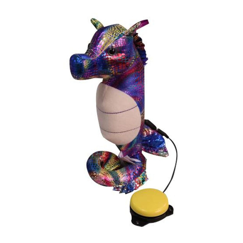
Enabling Devices Shelly Seahorse user guide

Horizon Fitness
Horizon Fitness BLH1250 instruction manual

