8
EN
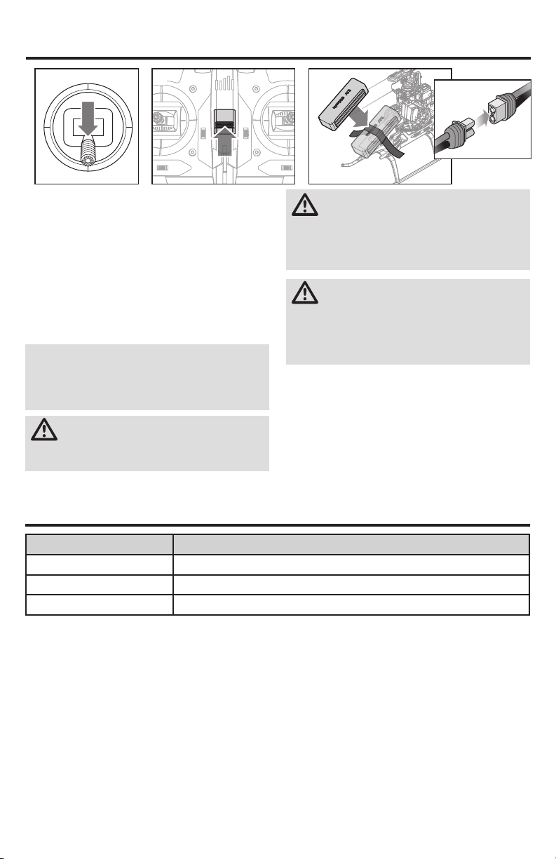
Transmitter and Receiver Binding
Low Voltage Cuto (LVC)
The ESC will continuously lower power to the motor until
complete shutdown when the battery reaches 9V under
load. This helps prevent over-discharge of the Li-Po
battery. Land immediately when the ESC activates LVC.
Continuing to y after LVC can damage the battery, cause
a crash or both. Crash damage and batteries damaged
due to over-discharge are not covered under warranty.
Repeatedly ying the helicopter until LVC activates will dam-
age the helicopter battery.
Disconnect and remove the Li-Po battery from the aircraft
after use to prevent trickle discharge. During storage, make
sure the battery charge does not fall below 3V per cell.
SMART Throttle (BNF Only)
The new line of Spektrum ESCs feature a telemetry func-
tion called SMART Throttle. SMART Throttle technology
combines the throttle signal with telemetry data from the
ESC on one normal three wire servo connector.
SMART Throttle ESCs can send current, voltage, ESC temp,
and mAh consumed. They can also pass along battery
data from compatible Spektrum SMART batteries. SMART
Throttle telemetry data shows up on your transmitter like
any other telemetry sensor.
For SMART Throttle to function you must have a SMART
Throttle ESC paired with a SMART Throttle telemetry
receiver, and a Spektrum DSMX transmitter with telemetry.
Only certain Spektrum products include SMART technology
compatibility, check your receiver and ESC manual for
more information. An update for your transmitter may be
required for SMART features.
(See www.spektrumrc.com to register and update your
transmitter.)
To activate SMART Telemetry:
1. Keep the vehicle powered on after binding the trans-
mitter to the receiver
2. Scroll to the Telemetry screen
3. Scroll to Settings
4. Select Auto Cong
To activate Speed infomation using SMART Telemetry:
5. After doing the initial SMART telemetry conguration
keep the vehicle powered on
6. Scroll to the Telemetry screen
7. Scroll to SMART ESC and double select
8. Scroll down to NEXT
9. Enter the values for the magnetic pole count of the
motor and the gear ratio (motor and gear ratio infor-
mation can be found in the manual for your vehicle)
When the radio is on and connected to a receiver sending
SMART Data, the SMART Logo will appear under the battery
logo on the home page and a signal bar will appear in the
top left corner of the screen. Scrolling down, past the servo
monitor, the SMART screens will appear. Select either ESC,
battery, or both for display to suit your preference.
RTF Your RTF transmitter comes prebound to the model. If you need to re-bind, follow the directions below.
This product requires an approved Spektrum DSM2®/DSMX®compatible transmitter. Refer the Transmitter
Setup Table to correctly setup your transmitter.
General Binding Procedure
1. Lower the throttle stick to the lowest position. Set all
trims to the center position.
2. Power off the transmitter (RF off for iX transmitters) and
move all switches to the 0 position. Move the throttle to
the low/off position.
3. Insert the bind plug into bind port extention cable on
the side of the helicopter.
4. Connect the ight battery to the ESC. The LED on the
receiver will ash orange rapidly when it enters bind
mode.
5. Press the bind button and power on your transmitter
(iX series transmitters put the transmitter into bind
mode).
6. Release the bind button after 2–3 seconds.The helicopter
is bound when the LED on the receiver turns solid orange.
7. Disconnect the ight battery and remove the bind plug.
Invert to Bind Procedure
1. Lower the throttle stick to the lowest position. Set all
trims to the center position.
2. Power off the transmitter (RF off for iX transmitters) and
move all switches to the 0 position. Move the throttle to
the low/off position.
3. Connect the ight battery to the ESC.
4. Flip the model upside down and hold for 15s. The LED
on the receiver will ash orange rapidly when it enters
bind mode. Turn the model upright and set it down.
5. Press the bind button and power on your transmitter
(iX series transmitters put the transmitter into bind
mode).
6. Release the bind button after 2–3 seconds. The
helicopter is bound when the LED on the receiver turns
solid orange.
7. Disconnect the ight battery.
®
It is possible to bind this model with a bind plug or using the invert to bind method.