TENETICS, LLC Ceres User manual
Who we are
Tenetics is committed to bringing precision agriculture technology to
small and medium-sized farms. Our Ceres wireless products help you
monitor and manage your farm from your computer or smart-phone.
Ceres is designed for agriculture:
Easy installation
Maintenance free
Long wireless range
Wide operating temperature
Rugged outdoor reliability
Ceres (Demeter) was the Greek and
Roman goddess of agriculture.
“Cereal” comes from her name.
Contact Us
Tenetics is located in suburban Maryland. For more information about
Ceres products, please contact us or visit our website.
Phone: 301-970-9700
Email: [email protected]
Web: https://www.tenetics.com
Tenetics, LLC
10630 Little Patuxent Pkwy
Columbia, MD 21044
®
TENETICS, LLC
Advanced Wireless Agriculture

Table of Contents
Overview ............................................................................................................................. 1
Package Contents ............................................................................................................. 1
Location/Mounting ......................................................................................................... 2
Installation ......................................................................................................................... 2
Custom Installation......................................................................................................... 3
Remote Locations ............................................................................................................ 4
Adding Sensors and Controllers……………………………………………………….. 4
Managing your Gateway…………………………………………………………………… 5
WiFi…….………………………………………………………………………………6
Devices………………………………………………………………………………..6
Sensors………………………………………………………………………………..7
System………………………………………………………………………………...7
Specifications .................................................................................................................... 8
FCC Notice ........................................................................................................................... 9
FCC Notice
This device complies with Part 15 of the FCC Rules. Operation is subject to the
following two conditions: (1) This device may not cause harmful interference,
and (2) this device must accept any interference received, including interference
that may cause undesired operation.
This device and its antenna(s) must not be co-located or operating in
conjunction with any other antenna or transmitter.
This equipment has been tested and found to comply with the limits for a Class B
digital device, pursuant to part 15 of the FCC Rules. These limits are designed to
provide reasonable protection against harmful interference in a residential
installation. This equipment generates, uses and can radiate radio frequency
energy and, if not installed and used in accordance with the instructions, may
cause harmful interference to radio communications. However, there is no
guarantee that interference will not occur in a particular installation. If this
equipment does cause harmful interference to radio or television reception,
which can be determined by turning the equipment off and on, the user is
encouraged to try to correct the interference by one or more of the following
measures:
● Reorient or relocate the receiving antenna.
● Increase the separation between the equipment and receiver.
● Connect the equipment into an outlet on a circuit different from that to
which the receiver is connected.
● Consult the dealer or an experienced radio/TV technician for help.
This equipment complies with FCC radiation exposure limits set forth for an
uncontrolled environment. This equipment should be installed and operated
with minimum distance 20cm between the radiator and your body.
Contains FCC ID: 2AHMR-ESP12F
FCC WARNING: Changes or modifications not expressly approved by the party
responsible for compliance could void the user’s authority to operate the
equipment.
9

Specifications
Power
• Typical power consumption is less than ½ Watt
• Mini USB power input
• Included power supply
◦ Input: 100-240VAC 50/60 Hz input, UL listed
◦ Output: 5vdc at up to 750mA
Physical
• 4.5”x 5.0”x 1.3”
• -40 to +85C operating temperature range
• Indoor operation (standard)
• Outdoor weatherproof enclosure available (option)
Wireless
• WiFi: 802.11 b/g/n compliant (2.4GHz)
◦ WPS push-button connection supported
◦ WPA/WPA2 encryption supported
◦ FCC, CE certified
• Ceres Long-Range Wireless:
◦ Long range sub-GHz frequency band
◦ Secure frequency hopping spread spectrum (FHSS)
◦ Advanced filtering against cellular and pager interference
◦ RP-SMA antenna, 1.2dBi gain
Getting Started
Congratulations on selecting Ceres for your precision
agriculture. This manual will help you get your WiFi
Gateway installed and running in less than 5 minutes.
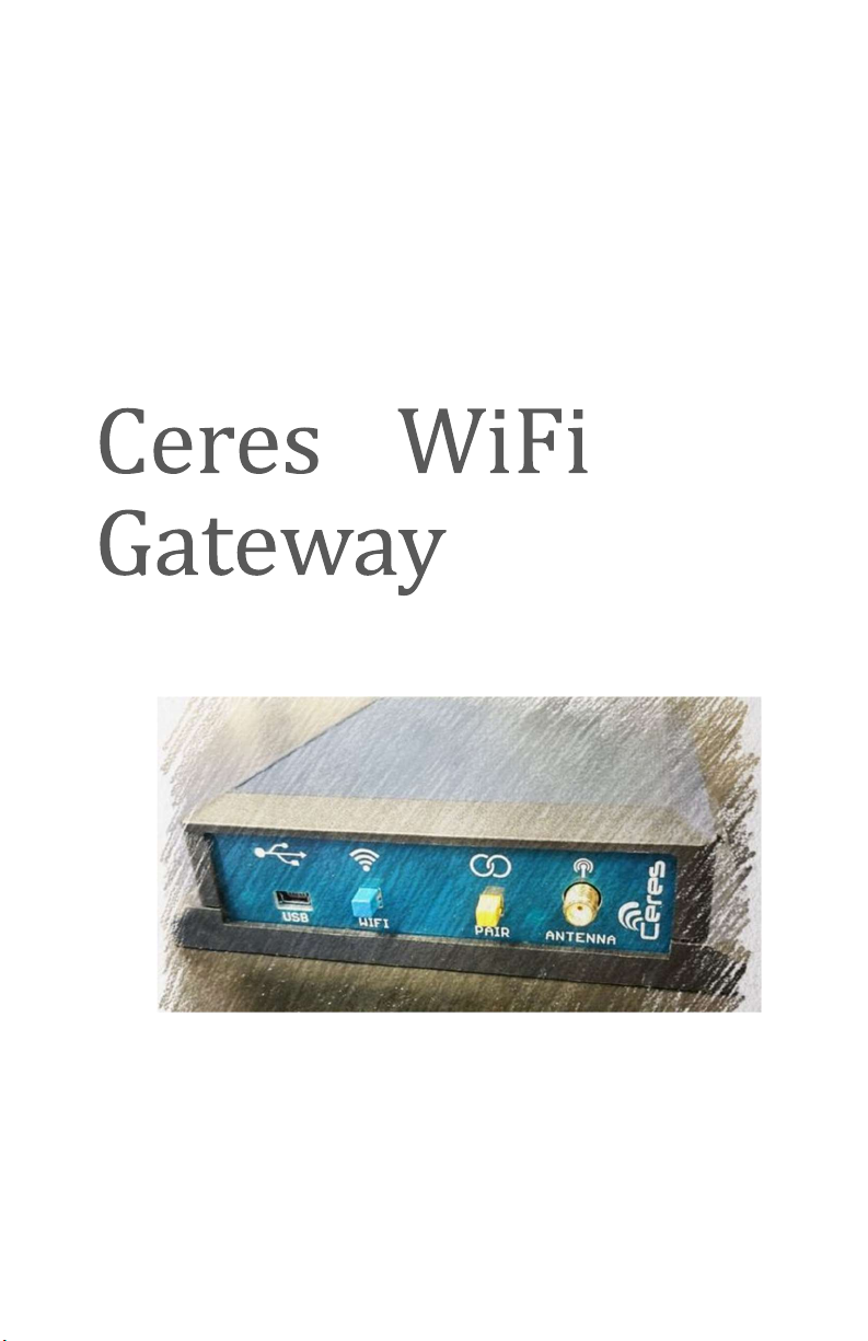
Overview
The WiFi Gateway receives transmissions
from your Ceres long-range wireless sensors
and controllers and forwards them to the
internet where your data is securely stored
and can be accessed any time using your
smart-phone or computer.
Package Contents
Your Gateway package contains:
• Ceres WiFi Gateway
• Ceres long range antenna
• AC Mains to USB power adapter
• USB A to mini-B power cable
8 1

Location/Mounting
The gateway can be wall mounted or placed on any flat surface. Pick a
location near an AC outlet and your WiFi Access Point/Router.
For wall mounting, use two 1/8” (#5) screws. If mounting to drywall,
use appropriate drywall anchors spaced 4.65” apart.
Once the location is chosen and the gateway is mounted, carefully thread
the provided antenna onto the gateway antenna connector until it is
finger tight. Do not overtighten.
Pro Tips:
* Mount indoors away from wet locations
* The antenna should be vertical
* Don’t put the antenna near metal objects
* Locate the gateway where it has an unobstructed view of your fields
Installation is as easy as 1,2,3
1. Plug the AC power adapter into the wall and connect it to your
gateway using the USB A to mini-B cable. The blue light on the
gateway will start blinking.
2. Press and hold the WPS button on your WiFi Access
Point/Router for a few seconds to enable connecting a new
device to your network (for the exact process, consult your
Access Point manual). Typically, a light on your Access Point
will start blinking.
3. Press the WIFI button on your gateway. After 10-60 seconds,
the blue light should stop blinking and stay on steadily to show
that the gateway is connected to the internet.
That’s all there is to it, you’re done!
Sensors Tab
The sensors tab
shows the most
recent readings
from each remote
sensor.
Press the refresh
button to update the
display.
System Tab
The system tab shows
the status of the
gateway and allows you
to:
• change the
gateway name
• set the time
zone
• enable the
receive filter
for areas with
radio
interference
2 7

WiFi Tab
The WiFi tab shows the
WiFi network your
gateway is connected to
and the WiFi HotSpot the
gateway creates.
You can disconnect from
the WiFi network using
the Forget button. If you
do this and are managing
your Gateway via WiFi,
the connection will end
and you must use WPS or
the Gateway HotSpot to
configure a new WiFi
connection.
Devices Tab
The Devices tab
shows the sensors
and controllers
paired with your
gateway.
You can add (pair) a
new device by
pressing the blue
“add sensor” button.
This has the same
effect as pressing
the yellow PAIR
button on the
gateway.
You can un
-
pair (delete) a device by pressing its red Unpair (X) button.
Custom Installation
The standard installation process may not be appropriate if:
• Your access point does not support WPS push-button connect
• You want to customize your gateway configuration
In these cases, you can quickly configure the gateway using your laptop
or smart-phone:
1. Plug the AC-to-USB power adapter into the wall and connect it
to your gateway using the USB A to mini-B cable. The blue light
on the gateway will start blinking.
2. On your laptop or phone, connect to the WiFi network named
CeresGateway_XXYYZZ.
3. When asked for the PSK (WPA2 password), enter the 10-digit
serial number found on the bottom of your gateway.
4. Depending on your operating system, you may see a warning
that the connection does not provide internet access; this is
normal, you should accept this and continue.
NOTE: Do not configure your phone or laptop to always connect
automatically to your Ceres gateway since it does not provide
internet access.
5. Start your favorite web browser and go to http://ceres.com
6.
Under the WiFi tab, enter the SSID and secret key (PSK) for your
access point then press the Connect button.
In a few seconds, your gateway will connect to your wireless network
and display its assigned IP address and signal strength. The blue light
will stay steadily on to show that the gateway is connected to the
internet.
6 3

Remote Locations
Where WiFi networking is not available, the gateway can be used with a
Cellular Hotspot. Hotspots provide WiFi internet access via the cellular
telephone network. Ask your cellular carrier about supported hotspots.
Due to the low power consumption of the Ceres WiFi Gateway and many
hotspots, these devices can even be solar powered for locations where
AC power is not available. Ask your Ceres dealer for details about Ceres
weatherproof enclosures and solar power options.
Adding Sensors and Controllers
When deploying a new Ceres device such as a soil sensor, rain gauge, or
irrigation controller, the device should first be paired with your gateway:
1. Press the yellow PAIR button on your gateway to enter pairing
mode; the yellow/orange LED will start blinking.
2. Press the PAIR button on the Ceres sensor or controller (you
may need to do this twice). The sensor and gateway will
exchange pairing information and the yellow/orange LED on
your sensor will blink several times to show the connection was
successful.
3. Deploy the sensor or controller in the field. Use the CeresDroid
app to record the GPS location of the device and give it an easy-
to-remember name.
Congratulations, you’re done!
Managing Your Gateway
For advanced users, the gateway provides a web-based management
interface. Most users will not need this, but advanced users may find it
helpful. You can access the management interface from the gateway
hotspot or through your WiFi network (after the gateway has joined the
network). Most popular web browsers are supported.
In Microsoft
Windows, use
Windows Explorer
to browse your
Network and locate
your CeresGateway:
Double-click on the Gateway to launch the management interface; you
will be asked for your username and password:
The default User Name is “admin” and the default password is the serial
number (S/N) printed on the bottom of the gateway. For security, you
should change the password using the Security tab after logging in.
4 5

WiFi Tab
The WiFi tab shows the
WiFi network your
gateway is connected to
and the WiFi HotSpot the
gateway creates.
You can disconnect from
the WiFi network using
the Forget button. If you
do this and are managing
your Gateway via WiFi,
the connection will end
and you must use WPS or
the Gateway HotSpot to
configure a new WiFi
connection.
Devices Tab
The Devices tab
shows the sensors
and controllers
paired with your
gateway.
You can add (pair) a
new device by
pressing the blue
“add sensor” button.
This has the same
effect as pressing
the yellow PAIR
button on the
gateway.
You can un
-
pair (delete) a device by pressing its red Unpair (X) button.
Custom Installation
The standard installation process may not be appropriate if:
• Your access point does not support WPS push-button connect
• You want to customize your gateway configuration
In these cases, you can quickly configure the gateway using your laptop
or smart-phone:
1. Plug the AC-to-USB power adapter into the wall and connect it
to your gateway using the USB A to mini-B cable. The blue light
on the gateway will start blinking.
2. On your laptop or phone, connect to the WiFi network named
CeresGateway_XXYYZZ.
3. When asked for the PSK (WPA2 password), enter the 10-digit
serial number found on the bottom of your gateway.
4. Depending on your operating system, you may see a warning
that the connection does not provide internet access; this is
normal, you should accept this and continue.
NOTE: Do not configure your phone or laptop to always connect
automatically to your Ceres gateway since it does not provide
internet access.
5. Start your favorite web browser and go to http://ceres.com
6.
Under the WiFi tab, enter the SSID and secret key (PSK) for your
access point then press the Connect button.
In a few seconds, your gateway will connect to your wireless network
and display its assigned IP address and signal strength. The blue light
will stay steadily on to show that the gateway is connected to the
internet.
6 3

Location/Mounting
The gateway can be wall mounted or placed on any flat surface. Pick a
location near an AC outlet and your WiFi Access Point/Router.
For wall mounting, use two 1/8” (#5) screws. If mounting to drywall,
use appropriate drywall anchors spaced 4.65” apart.
Once the location is chosen and the gateway is mounted, carefully thread
the provided antenna onto the gateway antenna connector until it is
finger tight. Do not overtighten.
Pro Tips:
* Mount indoors away from wet locations
* The antenna should be vertical
* Don’t put the antenna near metal objects
* Locate the gateway where it has an unobstructed view of your fields
Installation is as easy as 1,2,3
1. Plug the AC power adapter into the wall and connect it to your
gateway using the USB A to mini-B cable. The blue light on the
gateway will start blinking.
2. Press and hold the WPS button on your WiFi Access
Point/Router for a few seconds to enable connecting a new
device to your network (for the exact process, consult your
Access Point manual). Typically, a light on your Access Point
will start blinking.
3. Press the WIFI button on your gateway. After 10-60 seconds,
the blue light should stop blinking and stay on steadily to show
that the gateway is connected to the internet.
That’s all there is to it, you’re done!
Sensors Tab
The sensors tab
shows the most
recent readings
from each remote
sensor.
Press the refresh
button to update the
display.
System Tab
The system tab shows
the status of the
gateway and allows you
to:
• change the
gateway name
• set the time
zone
• enable the
receive filter
for areas with
radio
interference
2 7

Specifications
Power
• Typical power consumption is less than ½ Watt
• Mini USB power input
• Included power supply
◦ Input: 100-240VAC 50/60 Hz input, UL listed
◦ Output: 5vdc at up to 750mA
Physical
• 4.5”x 5.0”x 1.3”
• -40 to +85C operating temperature range
• Indoor operation (standard)
• Outdoor weatherproof enclosure available (option)
Wireless
• WiFi: 802.11 b/g/n compliant (2.4GHz)
◦ WPS push-button connection supported
◦ WPA/WPA2 encryption supported
◦ FCC, CE certified
• Ceres Long-Range Wireless:
◦ Long range sub-GHz frequency band
◦ Secure frequency hopping spread spectrum (FHSS)
◦ Advanced filtering against cellular and pager interference
◦ RP-SMA antenna, 1.2dBi gain
Getting Started
Congratulations on selecting Ceres for your precision
agriculture. This manual will help you get your WiFi
Gateway installed and running in less than 5 minutes.
Overview
The WiFi Gateway receives transmissions
from your Ceres long-range wireless sensors
and controllers and forwards them to the
internet where your data is securely stored
and can be accessed any time using your
smart-phone or computer.
Package Contents
Your Gateway package contains:
• Ceres WiFi Gateway
• Ceres long range antenna
• AC Mains to USB power adapter
• USB A to mini-B power cable
8 1

Table of Contents
Overview ............................................................................................................................. 1
Package Contents ............................................................................................................. 1
Location/Mounting ......................................................................................................... 2
Installation ......................................................................................................................... 2
Custom Installation......................................................................................................... 3
Remote Locations ............................................................................................................ 4
Adding Sensors and Controllers……………………………………………………….. 4
Managing your Gateway…………………………………………………………………… 5
WiFi…….………………………………………………………………………………6
Devices………………………………………………………………………………..6
Sensors………………………………………………………………………………..7
System………………………………………………………………………………...7
Specifications .................................................................................................................... 8
FCC Notice ........................................................................................................................... 9
FCC Notice
This device complies with Part 15 of the FCC Rules. Operation is subject to the
following two conditions: (1) This device may not cause harmful interference,
and (2) this device must accept any interference received, including interference
that may cause undesired operation.
This device and its antenna(s) must not be co-located or operating in
conjunction with any other antenna or transmitter.
This equipment has been tested and found to comply with the limits for a Class B
digital device, pursuant to part 15 of the FCC Rules. These limits are designed to
provide reasonable protection against harmful interference in a residential
installation. This equipment generates, uses and can radiate radio frequency
energy and, if not installed and used in accordance with the instructions, may
cause harmful interference to radio communications. However, there is no
guarantee that interference will not occur in a particular installation. If this
equipment does cause harmful interference to radio or television reception,
which can be determined by turning the equipment off and on, the user is
encouraged to try to correct the interference by one or more of the following
measures:
● Reorient or relocate the receiving antenna.
● Increase the separation between the equipment and receiver.
● Connect the equipment into an outlet on a circuit different from that to
which the receiver is connected.
● Consult the dealer or an experienced radio/TV technician for help.
This equipment complies with FCC radiation exposure limits set forth for an
uncontrolled environment. This equipment should be installed and operated
with minimum distance 20cm between the radiator and your body.
Contains FCC ID: 2AHMR-ESP12F
FCC WARNING: Changes or modifications not expressly approved by the party
responsible for compliance could void the user’s authority to operate the
equipment.
9
Who we are
Tenetics is committed to bringing precision agriculture technology to
small and medium-sized farms. Our Ceres wireless products help you
monitor and manage your farm from your computer or smart-phone.
Ceres is designed for agriculture:
Easy installation
Maintenance free
Long wireless range
Wide operating temperature
Rugged outdoor reliability
Ceres (Demeter) was the Greek and
Roman goddess of agriculture.
“Cereal” comes from her name.
Contact Us
Tenetics is located in suburban Maryland. For more information about
Ceres products, please contact us or visit our website.
Phone: 301-970-9700
Email: [email protected]
Web: https://www.tenetics.com
Tenetics, LLC
10630 Little Patuxent Pkwy
Columbia, MD 21044
®
TENETICS, LLC
Advanced Wireless Agriculture
Other manuals for Ceres
1
Table of contents
Other TENETICS, LLC Gateway manuals

Popular Gateway manuals by other brands


ZyXEL Communications
ZyXEL Communications P-870HN-51B Specifications

Cisco
Cisco IG21 Series installation guide

HP
HP hn200e quick start guide

ZyXEL Communications
ZyXEL Communications Prestige 316 user guide

SOMFY
SOMFY 5128651 Installation and user guide

ZyXEL Communications
ZyXEL Communications P-660HN series user guide


