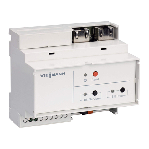
Viessmann Vitogate 300 Operating instructions

Installation and service instructions
for contractors
VIESMANN
Vitogate 300
Type BN/MB
Communication with heating systems via BACnet and Modbus
For applicability, see the last page
VITOGATE 300
5672 142 GB 10/2014 Please keep safe.

2
Please follow these safety instructions closely to
prevent accidents and material losses.
Safety instructions explained
Danger
This symbol warns against the risk of injury.
!Please note
This symbol warns against the risk of material
losses and environmental pollution.
Note
Details identified by the word "Note" contain additional
information.
Target group
These instructions are exclusively intended for quali-
fied contractors.
■Work on electrical equipment must only be carried
out by a qualified electrician.
■The system must be commissioned by the system
installer or a qualified person authorised by the
installer.
Regulations
Observe the following when working on this system:
■National installation regulations
■Statutory regulations regarding the prevention of
accidents
■Statutory regulations regarding environmental pro-
tection
■The Code of Practice of relevant trade associations
■All current safety regulations as defined by DIN, EN,
DVGW, VDE and all locally applicable standards
aÖNORM, EN and ÖVE
cSEV, SUVA, SVTI and SWKI
If you smell flue gas
Danger
Flue gas can lead to life threatening poisoning.
■Shut down the heating system.
■Ventilate the installation site.
■Close all doors in the living space.
Flue systems and combustion air
Ensure that flue systems are clear and cannot be
sealed, for instance due to accumulation of conden-
sate or other causes. Ensure a sufficient supply of
combustion air.
Instruct system users that subsequent modifications to
the building characteristics are not permissible (e.g.
cable/pipework routing, cladding or partitions).
Danger
Leaking or blocked flue systems, or an insuffi-
cient supply of combustion air can cause life
threatening poisoning from carbon monoxide in
the flue gas.
Ensure the flue system is in proper working
order. Apertures for supplying combustion air
must be non-closable.
Extractors
Operating appliances that extract air to the outside
(cooker hoods, extractors, air conditioning units, etc.)
can create negative pressure. If the boiler is operated
at the same time, this can lead to reverse flow of the
flue gas.
Danger
The simultaneous operation of the boiler and
appliances that extract air to the outside can
result in life threatening poisoning due to
reverse flow of the flue gas.
Fit an interlock circuit or take suitable steps to
ensure a sufficient supply of combustion air.
Working on the system
■Isolate the system from the power supply (e.g. by
removing the separate fuse or by means of a mains
isolator) and check that it is no longer 'live'.
■Safeguard the system against reconnection.
Danger
Hot surfaces can cause burns.
■Before maintenance or service work, switch
OFF the appliance and let it cool down.
■Never touch hot surfaces on the boiler, burner,
flue system or pipework.
!Please note
Electronic assemblies can be damaged by elec-
trostatic discharge.
Before beginning work, touch earthed objects,
such as heating or water pipes, to discharge
static loads.
Repair work
!Please note
Repairing components that fulfil a safety func-
tion can compromise the safe operation of the
system.
Faulty components must be replaced with origi-
nal Viessmann spare parts.
Safety instructions
Safety instructions
5672 142 GB
3
Auxiliary components, spare and wearing parts
!Please note
Spare and wearing parts that have not been tes-
ted together with the system can compromise its
function. Installing non-authorised components
and making non-approved modifications or con-
versions can compromise safety and may inva-
lidate the warranty.
For replacements, use only original spare parts
supplied or approved by Viessmann.
Safety instructions
Safety instructions (cont.)
5672 142 GB

4
1. Preparing for installation ................................................................................................................ 5
2. Installation sequence Installing the Vitogate 300 ..................................................................... 6
Making the LON connection .................................................................. 6
Power supply ......................................................................................... 8
■Directives ............................................................................................ 8
■Power supply via the mains isolator ................................................... 8
■Power supply independent of the mains isolator ................................ 9
3. Commissioning and
adjustment
Connection diagram ............................................................................... 10
Integrating the Vitotronic control unit into LON ...................................... 10
■LON system number and subscriber number ..................................... 10
■Updating LON subscriber list .............................................................. 11
■Carrying out subscriber check ............................................................ 11
4. Connection diagram ................................................................................................................ 12
5. Commissioning ................................................................................................................ 13
6. Parts list ................................................................................................................ 14
7. Specification Vitogate 300, type BN/MB ..................................................................... 15
Power supply unit .................................................................................. 15
8. Certificates Declaration of conformity ....................................................................... 16
9. Keyword index ................................................................................................................ 17
Index
Index
5672 142 GB

5
Intended use
Install and operate Vitogate products as intended in
conjunction with the electronic control units and con-
trollers for the Viessmann heat and power generators
designed for this system, giving due consideration to
the associated installation, service and operating
instructions. In particular, observe the current and volt-
age specifications for connections and hook-ups.
Use Vitogate products exclusively for monitoring, oper-
ating and optimising systems with the user and com-
munication interfaces specified for this purpose in the
relevant printed documentation. In the case of commu-
nication interfaces, ensure on site that the system
requirements specified in the product documentation
are met at all times for every transfer medium
employed. Only use the specified components for the
mains power supply (e.g. mains power adaptors).
Product information
The Vitogate 300, type BN/MB gateway is designed to
hook-up Vitotronic control units with integral LON com-
munication module (accessory) to BACnet or Modbus
control systems. For supported appliances/devices
and further information, see www.vitogate.info.
The Vitogate 300, type BN/MB must be integrated into
the BACnet or Modbus control system by an author-
ised contractor.
Functions
The Vitogate 300, type BN/MB enables system users
to utilise the following functions in conjunction with a
BACnet or Modbus control system:
■Transferring heating system operating states
■Setting heating system parameters
■Relaying fault and error messages
Preparing for installation
5672 142 GB
Installation

6
+ + - -
Output DC
DC OK
L(+)N(-)
STEP POWER
100
65
A B
Fig. 1
APower supply unit (standard delivery)
BVitogate 300
Vitogate 300, type BN/MB and its power supply unit
are suitable for mounting on a support rail (TS 35 to
EN 50 022: 35 x 15 and 35 x 7.5) inside control panels.
Making the LON connection
The Viessmann LON is designed for "Line" BUS topol-
ogy with a terminator at both ends (accessories). Fur-
ther information can be found in the "Viessmann LON
manual"; see www.viessmann.de/lon.
The transfer distances for LON are subject to the elec-
trical properties of the respective cable. For this rea-
son, only use the specified cable types. Use only one
cable type within each LON.
Cable types (on site):
■2-core cable, CAT5, screened
■JY(St)Y 2 x 2 x 0.8 mm (telephone cable)
Observe the cabling requirements for the operation of
the LON interface FTT 10-A (see www.echelon.com).
All Viessmann appliances are connected with RJ45
connectors. The Viessmann LON always requires
cores "1" and "2" plus the screen. The cores are inter-
changeable. The installation is therefore reverse polar-
ity protected.
Note
When connecting devices and routing cables, observe
the requirements of safety category II. That is 8.0 mm
air and creep paths or 2.0 mm insulation thickness
against 'live' components.
Ensure the safe electrical separation of all on-site com-
ponents (incl. PC/laptops) conforms to EN 60 335 or
IEC 65.
Installation sequence
Installing the Vitogate 300
5672 142 GB
Installation

7
Connection with LON cable
C
A A B
D
C
D
Fig. 2 Installation spacing ≤ 7 m
AVitotronic control unit
BVitogate 300
CTerminator
DLON cable, 7 m long
Connection with LON cable and LON coupling
C
E
A A B
EDD D EE DD
C
D
Fig. 3 Installation spacing 7 to 21 m
AVitotronic control unit
BVitogate 300
CTerminator
DLON cable, 7 m long:
Max. 3 cables between 2 devices
ELON coupling
Connection with on-site cable and LON plug
C
A A B
E
C
E
F
≤ 900 m
D D DD
Fig. 4 Installation spacing ≤ 900 m (with LON con-
nector)
AVitotronic control unit
BVitogate 300
CTerminator
DLON plug
EOn-site cable
FUp to 99 subscribers
Connection with LON cable, on-site cable and LON socket
≤ 900 m
F
C
D
C
D D D
E
F F F
E
A A GB
Fig. 5 Installation spacing ≤ 900 m (with LON sock-
ets)
AVitotronic control unit
BVitogate 300
CTerminator
DLON cable, 7 m long
EOn-site cable
FLON sockets
GUp to 99 subscribers
Installation sequence
Making the LON connection (cont.)
5672 142 GB
Installation

8
Directives
Regulations
Connect the power supply and implement all safety
measures (e.g. RCD circuit) in accordance with
IEC 60364, the connection requirements of your local
power supply utility, and VDE or national regulations.
Protect the Vitogate 300 power cable with an appropri-
ate fuse.
For oil and gas combustion equipment over 100 kW,
according to the Sample Combustion Ordinance
"FeuVO", an "emergency stop switch" must be instal-
led on site outside the installation room. Observe the
national combustion equipment regulations for your
local region. For combustion equipment to EN
50156-1, the "emergency stop" installed on site must
comply with the requirements of EN 50156-1. Fit the
"emergency stop switch" outside the installation room.
Install an isolator in the power cable to provide omnip-
olar separation from the mains for all active conduc-
tors, corresponding to overvoltage category III (3 mm)
for full isolation. This isolator must be fitted in the per-
manent electrical installation in line with installation
requirements.
We also recommend installing an AC/DC-sensitive
RCD (RCD class B ) for DC (fault) currents that
can occur with energy efficient equipment.
Recommended power cable
3-core cable:
■H05VV-F3G 1.5 mm2
■H05RN-F3G 1.5 mm2
Power supply via the mains isolator
When the heating system is switched off via the mains
isolator, the Vitogate 300 and the Vitotronic control unit
are also switched off.
No data is transferred to the BACnet or Modbus con-
trol system.
Danger
Incorrect core allocation can result in serious
injury and damage to the appliance.
Take care not to interchange wires "L1" and "N":
L1 Brown
N Blue
PE Green/yellow
B
C
DE
G
F
A
L1
PE
N
40
L N
+24 V GND
N
L
BN
BU
GNYE
+ -
24 V DC
100-240 V AC
Fig. 6
AVitogate 300
BPower supply 100 to 240 V~, 45 to 65 Hz
CFuse (max. 16 A)
DMains isolator, 2-pole, on site (if installed)
EJunction box (on-site)
FVitotronic control unit power supply (plug fÖ)
GPower supply unit
Installation sequence
Power supply
5672 142 GB
Installation

9
1. Check whether the power cable to the Vitotronic
control unit has appropriate fuse protection.
2. Terminate the power cable on site in terminal box
E and at plug fÖ.
3. Insert plug fÖ into the Vitotronic control unit.
Colour coding in accordance with DIN IEC 60757
BN/MB Brown
BU Blue
GNYE Green/yellow
Power supply independent of the mains isolator
When the heating system is switched off via the mains
isolator, the Vitogate 300 remains on, whilst the
Vitotronic control unit is switched off.
No data is transferred to the BACnet or Modbus con-
trol system.
B
C
E
D
G
F
A
L1
PE
N
40
L N
+24 V GND
BN
BU
GNYE
+ -
24 V DC
100-240 V AC
N
L
Fig. 7
AVitogate 300
BPower supply 100 to 230 V~, 45 to 65 Hz
CFuse (max. 16 A)
DJunction box (on-site)
EMains isolator, 2-pole, on site (if installed)
FVitotronic control unit power supply (plug fÖ)
GPower supply unit
1. Check whether the power cable to the Vitotronic
control unit has appropriate fuse protection.
2. Terminate the power cable on site in terminal box
D and at plug fÖ.
Danger
Incorrect core allocation can result in serious
injury and damage to the appliance.
Take care not to interchange wires "L1" and
"N":
L1 Brown
N Blue
PE Green/yellow
3. Insert plug fÖ into the Vitotronic control unit.
Installation sequence
Power supply (cont.)
5672 142 GB
Installation

10
LON
PWRRS485
+
-24 V AC/DCDC
B+A-AGNDShld
ON
OFF
123
BIAS
BIAS
Term
LON
LAN
USB
Reset
Power Status
RX TX
LON status
Fig. 8
LON status Illuminates green
RX Flashes yellow: Device receives data.
TX Flashes yellow: Device sends data.
Power Illuminates green: Power ON, operating
voltage 'live'
Status Multicolour status LED: red, green, orange
Meaning of the status indication:
Illuminates
green.
Reset is being held down.
Flashes green. Standard operation
Flashes green/
red.
DHCP server enabled
Illuminates or-
ange.
Indication during re-start
Flashes or-
ange.
Indication following the start phase
when there is no gateway configura-
tion
Flashes red. Indication in the case of BUS errors
in the MS/TP network (e.g. framing
errors)
Illuminates red. Indication prior to a reset whilst files
are being connected.
Integrating the Vitotronic control unit into LON
The LON communication module (accessory) must be
plugged into the Vitotronic control unit.
Note
The data transfer via LON can take several minutes.
LON system number and subscriber number
Set LON system number, LON subscriber number and
further functions via code 2.
Vitotronic control unit service instructions and
the following table
Note
In the same LON system, each number an only be
allocated once.
Only one Vitotronic control unit per system may be
programmed as the fault manager.
Commissioning and adjustment
Connection diagram
5672 142 GB
Service

11
Example: Single boiler system with Vitotronic 300, Vitotronic 200-H heating circuit control unit down-
stream and Vitogate 300, type BN/MB
Vitotronic 300 Vitotronic 200-H Vitogate 300
LON LON
Subscriber no. 1
Code "77:1"
Subscriber no. 10
Code "77:10"
Delivered condition Vitogate 300:
Subscriber no. 97
Control unit is fault manager
Code "79:1"
Control unit is not fault manager.
Code "79:0"
Device is fault manager.
Viessmann system number
Code "98:1"
Viessmann system number
Code "98:1"
—
LON subscriber fault monitoring
Code "9C:20"
LON subscriber fault monitoring
Code "9C:20"
—
Updating LON subscriber list
Vitotronic control unit installation and service
instructions
Carrying out subscriber check
Vitotronic control unit installation and service
instructions
Commissioning and adjustment
Integrating the Vitotronic control unit into LON (cont.)
5672 142 GB
Service

12
D
LON
PWRRS485
+
-24 V AC/DCDC
B+A-AGNDShld
ON
OFF
123
BIAS
BIAS
Term
F
LON
LAN
USB
E
Reset
Power Status
RX TX
LON status
A
B
C
Fig. 9
ADIP switch:
1 Bias voltage for RS 485 interface
2 Bias voltage for RS 485 interface
3 120 Ω terminator
BRS 485 connection: Interface for BACnet MS/TP or
Modbus RS 485
CSupply voltage 24 V–: Power supply unit, secon-
dary side
DLAN connection with PC/Laptop or BACnet IP or
Modbus TCP/IP
ELON connection, 2 pce RJ 45 sockets, screened
FUSB connection for software updates
Connection diagram
Connection diagram
5672 142 GB
Service

13
Devices required for commissioning:
■PC/laptop with the following equipment:
–Minimum monitor resolution 1024 x 768
–Integral or external Ethernet network module
–PDF Reader
■Supported web browsers:
–MS Internet Explorer V 7 or higher
–Mozilla Firefox V 2 or higher
–Mobile Safari V 3.1 or higher
–Google Chrome V 18.0 or higher
■Twisted pair network cable
Enabling the DHCP server
Dynamic Host Configuration Protocol (DHCP) makes
IP addresses available to clients on request.
If the computer has been set up as DHCP client
(standard setting), the DHCP server of the
Vitogate 300 can be used to provide an IP address.
Hold down the reset button on the Vitogate 300 for at
least 5 s, but no longer than 10 s.
The DHCP server has been enabled once the LED
LON status flashes green/red alternately.
Note
The DHCP server does not need to be enabled if a
manual IP address is to be used.
Creating an Ethernet network
Connect the computer network module by means of a
twisted pair network cable with the RJ45 connection of
the Vitogate 300.
Creating a connection with the Vitogate 300 configuration webserver
An IP address is automatically assigned to the com-
puter if the DHCP server has been enabled.
If a manual IP address is to be used, make the follow-
ing settings on the computer:
■IP address: 169.254.0.2 (or higher)
■Subnet mask: 255.255.0.0
■Standard gateway: Leave blank.
Calling up the Vitogate 300 configuration webserver
Open the Vitogate 300 configuration screens:
Start web browser:
■Enter IP address 169.254.0.1 into the address line.
■User name: vitogate
■Password: viessmann
You can change the password later.
The gateway default screen is called up.
Note
The configuration screens are described in the integral
Vitogate 300 online help.
Commissioning
Commissioning
5672 142 GB
Service

14
Pos. Part
0001 Standard unit Vitogate 300, type BN/MB
0002 LON cable, 7 m long
0003 Power supply unit
0005 LAN cable
0006 Vitogate 300, type BN/MB installation and service instructions
0005 0006
0002
0001
0003
Fig. 10
Parts list
Parts list
5672 142 GB
Service

15
Mains voltage 12 to 24 V AC/DC
Power consumption Max. 320 mA
Rated output Max. 3.85 W
Frequency range 47 to 63 Hz
Permiss. ambient temperature
■During operation 0 to 45 °C
■During transport and storage −10 to +65 °C
Permiss. humidity
■During operation 20 to 80 % relative humidity, non-condensing
■During storage and transport 10 to 85 % relative humidity, non-condensing
Dimensions (height x width x depth) 100 x 48 x 70 mm
Installation Top-hat rail TS35 to EN 50022
Power supply unit STEP-PS 1AC/24DC 0.75/FL.
Power supply unit
Rated voltage 100 to 240 V~
Rated frequency 45 to 65 Hz
Output voltage 24 V– ±1 %
Output current max. 1.4 A
IP rating IP20
Safety category II
Permiss. ambient temperature
■Operation –25 to +70 °C
> 55 °C line loss
■Storage and transport −40 to +85 °C
Max. humidity 95 % relative humidity at 25 °C, non-condensing
Dimensions (height x width x depth) 150 x 36 x 43 mm
Specification
Vitogate 300, type BN/MB
5672 142 GB
Service

16
We, Viessmann Werke GmbH & Co KG, D-35107 Allendorf, declare as sole responsible body that the product
Vitogate 300, type BN/MB complies with the following standards:
EN 60335-1 EN 60950-1
EN 55024 EN 55022
This product is _ designated in accordance with the terms of the following Directives:
1999/5/EC 2004/108/EC
2006/95/EC 2011/65/EU
Allendorf, 01 August 2014 Viessmann Werke GmbH & Co KG
Authorised signatory Manfred Sommer
Certificates
Declaration of conformity
5672 142 GB
Service

17
B
BACnet...................................................................5, 12
C
Control panel................................................................6
E
Electrical connections
– Overview................................................................. 10
– Power supply.............................................................8
F
Fault manager............................................................ 11
I
Installation.................................................................... 6
Intended use................................................................ 5
L
LON............................................................................10
– cable..........................................................................7
– Control unit integration............................................ 10
– Coupling....................................................................7
– Fault monitoring.......................................................11
– Making a connection................................................. 6
– on-site cable..............................................................7
– Socket....................................................................... 7
– Subscriber check.....................................................11
– Subscriber list..........................................................11
– Subscriber number..................................................10
– System number....................................................... 10
LON communication module......................................10
M
Modbus.................................................................. 5, 12
P
Power cable................................................................. 8
Power supply
– Directives.................................................................. 8
– Independent of mains isolator................................... 9
– Via mains isolator......................................................8
Power supply unit
– Specification............................................................15
Product information...................................................... 5
S
Specification...............................................................15
Keyword index
Keyword index
5672 142 GB

18
5672 142 GB

19
5672 142 GB

20
Applicability
Serial No.:
7543964
Viessmann Limited
Hortonwood 30, Telford
Shropshire, TF1 7YP, GB
Telephone: +44 1952 675000
Fax: +44 1952 675040
E-mail: [email protected]
Viessmann Werke GmbH & Co. KG
D-35107 Allendorf
Telephone: +49 6452 70-0
Fax: +49 6452 70-2780
www.viessmann.com
5672 142 GB Subject to technical modifications.
Other manuals for Vitogate 300
4
This manual suits for next models
1
Table of contents
Other Viessmann Gateway manuals

Viessmann
Viessmann WAGO BACnet/IP Quick guide

Viessmann
Viessmann WAGO 750-8212/000-100 Operating instructions

Viessmann
Viessmann WAGO KNX/TP gateway Operating instructions

Viessmann
Viessmann WAGO MB/TCP gateway Quick guide

Viessmann
Viessmann Vitogate 300 Quick guide

Viessmann
Viessmann Vitogate 200 Quick guide

Viessmann
Viessmann WAGO MB/TCP gateway Operating instructions

Viessmann
Viessmann Vitogate 300 Operator's manual