Panasonic KX-TDA0480 User manual

Model No. KX-TDA0480
4-Channel VoIP Gateway Card
Getting Started
Thank you for purchasing the Panasonic 4-Channel VoIP Gateway Card, KX-TDA0480.
Please read this manual carefully before using this product and save this manual for future use.

2 Getting Started
Table of Contents
1 Overview ..........................................................................................5
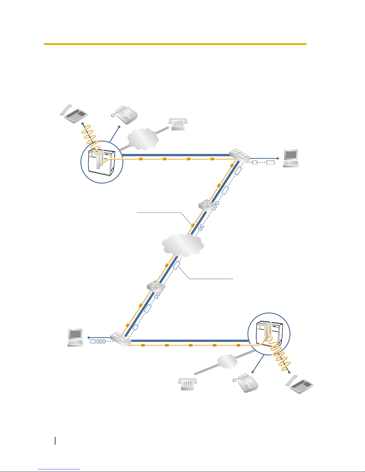
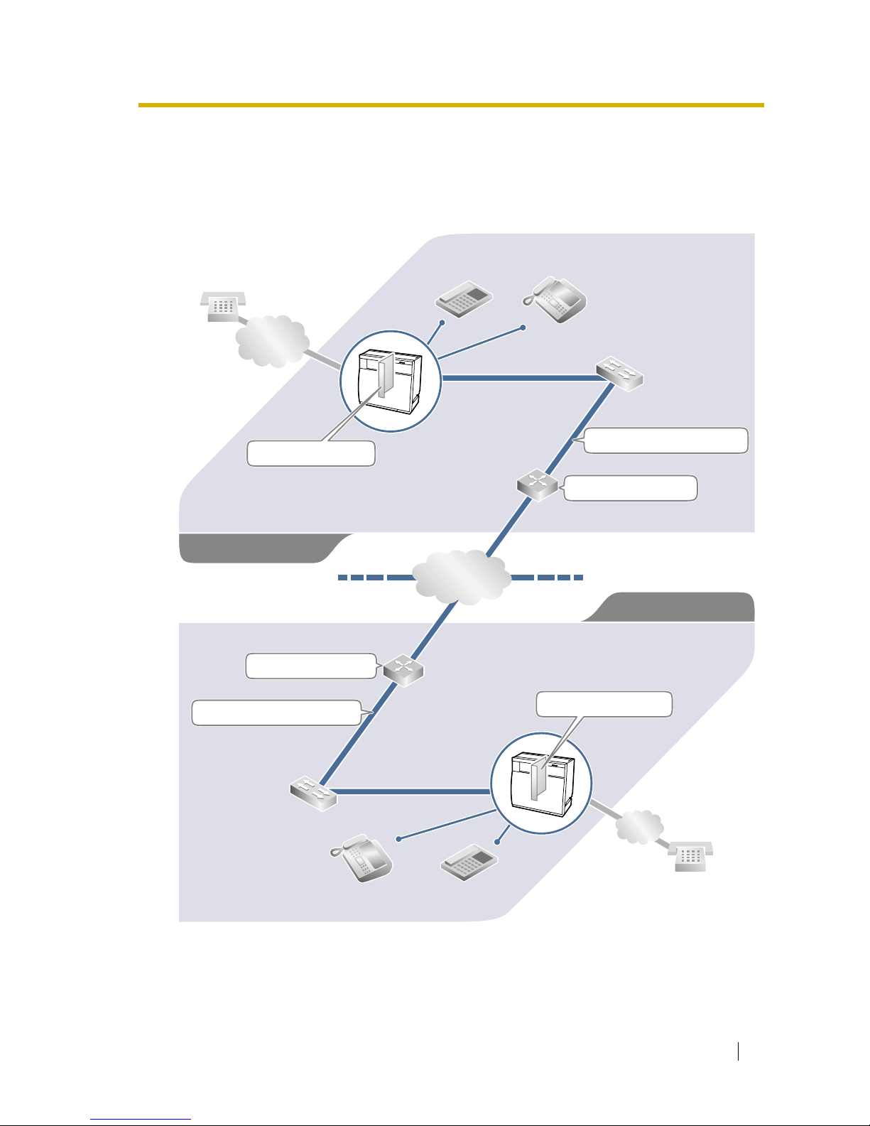
1.1 Example Network Diagram ..................................................................................... 6
1.2 Network Devices and Numbering Plan.................................................................. 7
1.2.1 Network Application................................................................................................... 8
1.2.2 Numbering Plan Example ......................................................................................... 8
1.2.3 Numbering Plan Summary ...................................................................................... 12
2 Physical Installation ......................................................................13
2.1 Installation ............................................................................................................. 14
2.1.1 Names and Locations.............................................................................................. 14
2.1.2 DIP Switch Settings................................................................................................. 14
2.1.3 Installing the VoIP Gateway Card to the Hybrid IP-PBX.......................................... 15
2.1.4 Indication Light (LED).............................................................................................. 16
2.2 Cable Connection.................................................................................................. 17
2.2.1 RS-232C Cable Connection .................................................................................... 17
2.2.2 10BASE-T Cable Connection.................................................................................. 18
3 Logical Installation (Maintenance Console Software) ...............19
3.1 The Maintenance Console Software (MCS) ....................................................... 20
3.1.1 Installing the MCS ................................................................................................... 20
3.1.2 Starting MCS and Logging In .................................................................................. 21
3.1.3 MCS Main Directory Window .................................................................................. 21
3.1.4 RS-232C Port Setting.............................................................................................. 21
3.1.5 Changing the Password .......................................................................................... 23
3.2 Creating New Group and Gateway....................................................................... 24
3.2.1 Creating a New Unit Group (Network)..................................................................... 24
3.2.2 Creating New Gateways (VoIP Gateway Card) ....................................................... 24
3.3 Configuring Domain Name System (DNS) Data ................................................. 27
3.3.1 Creating DNS Data.................................................................................................. 27
3.4 Configuring Office Data........................................................................................ 29
3.4.1 Editing Office Data .................................................................................................. 29
3.5 Transferring Data to the Units.............................................................................. 32
3.5.1 Transferring Data ..................................................................................................... 32
3.6 Synchronising Time and Date of the Units ......................................................... 33
3.6.1 Synchronising Time and Date ................................................................................. 33
4 Programming the Hybrid IP-PBX .................................................35
4.1 PC Programming ................................................................................................... 36
A Additional Information ..................................................................39
A1 Numbering Plan Example Alternative ................................................................. 40
A1.1 Extension Number Method...................................................................................... 40
A2 Firewalls ................................................................................................................. 43
A2.1 Firewalls .................................................................................................................. 43
A3 Optimising Performance....................................................................................... 45
A3.1 Voice Volume........................................................................................................... 45
A3.2 Transmission Delays................................................................................................ 45

Getting Started 3
A3.3 Priority Control .........................................................................................................46
A3.4 Recovery Delay and Jitter Buffer .............................................................................46
A3.5 Internet, Intranet, and Virtual Private Networks (VPN) ............................................46

4 Getting Started

Getting Started 5
Section 1
Overview
Panasonic Hybrid IP-PBX with VoIP Gateway Card will
allow organisations to route both voice and fax
communications over digital data networks.
The VoIP Gateway Card, designed to be easily
integrated into existing LAN/WAN environments,
seamlessly bridges Public Switched Telephone
Network (PSTN) and analogue telephone with digital
data networks without interrupting or compromising
ongoing data communications. Because
communications do not take place over conventional
telephone networks, the high cost of long distance
communications is virtually eliminated.

1.1 Example Network Diagram
6 Getting Started
1.1 Example Network Diagram
The following diagram illustrates a simple VoIP network connecting Hybrid IP-PBXs at 2
different locations. The VoIP Gateway Card converts outgoing voice or fax signals into IP data
packets for transmission. On the incoming side, it reverses this process and translates the
packets back into appropriate voice or fax signals.
PSTN
(Public Switched
Telephone Network)
IP Network
PSTN
Voice signals are converted
into IP data packets.
Router
Switching HUB
Hybrid IP-PBX
with VoIP Gateway Card
Other data packets
Voice data packets

1.2 Network Devices and Numbering Plan
Getting Started 7
1.2 Network Devices and Numbering Plan
Once the installation of VoIP Gateway Cards begins, network configuration information needs
to be on-hand. Referring to this example diagram, consult your network administrator to obtain
necessary information to configure your own network.
PSTN
(Public Switched
Telephone Network)
IP Network
Chicago Office
PBX Office Code: 41
PSTN Trunk Number: 9
TIE Line Access Number: 7
PSTN
Local Telephone
123-4567
Extn. 301
(300-399)
PBX Office Code: 35
PSTN Trunk Number: 9
TIE Line Access Number: 7
Extn. 201
(200-299)
Local Telephone
456-7890
G3 Fax Extn. 501
(500-599)
G3 Fax Extn. 601
(600-699)
Route IP: 200.45.11.1
Subnet Mask: 255.255.255.0
Unit IP: 200.45.11.35
Subnet Mask: 255.255.255.0
Los Angels Office
Route IP: 199.176.64.1
Unit IP: 199.176.64.41

1.2 Network Devices and Numbering Plan
8 Getting Started
1.2.1 Network Application
QSIG Line Service Interface
QSIG line service allows PBX to support communications with other company members in a
private network where the PBX is included. Implementation of VoIP Gateway Cards provides
a VoIP interface to employ QSIG line service between Hybrid IP-PBXs at different locations by
using IP network instead of conventional telephone networks.
Types of IP Network
The VoIP Gateway Card's quality of performance depends on the type of network in use.
Manageable networks in which static*1 IP addresses can be used provide better quality of
service compared to unmanageable networks such as the Internet, where quality of service is
not guaranteed.
Firewall
A firewall protects the internal networks of an organisation against unauthorised penetration
from outside. When routing a VoIP network through a firewall, some performance degradation
may result. If for practical reasons you must route the network through a firewall, refer to "A2
Firewalls" for more details.
1.2.2 Numbering Plan Example
There are 2 methods to plan your numbering system as follows:
This section provides the network numbering mechanism using the PBX Office Code method
(see "A1 Numbering Plan Example Alternative" for the example using the Extension Number
method) based on the previous example diagram. Configure your network referring to this
example.
*1 Dynamic IP addressing (using DHCP/BOOTP) is not supported.
Examples of recommended IP network
• Digital Leased Line
•IP-VPN
•FrameRelay
Not recommended
• Internet
(Delays and loss in data transmission
can cause degradation in speech
quality.)
PBX Office Code
method
In addition to the destination number, the caller dials the unique Office
Code of the PBX to which the called party is connected. Therefore, each
PBX in the network can have the same extension numbering scheme.
That is, for example, each PBX in the network can have an extension
whose number is 201.
Extension
Number method
The caller dials only the destination number of the called party to call
through PBXs at different locations (hence there are less digits to dial than
with the PBX Office Code method). To employ the Extension Number
method, no 2 PBX can have extensions sharing the same number. That
is, for example, if 1 PBX in the network has an extension whose number
is 201, no other PBX can have an extension with the same number (201).

1.2 Network Devices and Numbering Plan
Getting Started 9
IP Addressing Information
IP addressing information is typically supplied by a network administrator. Consult your
network administrator for specific values.
PBX Numbering Information
PBX numbering information is necessary to setup phone numbers for a VoIP network.
Configure the numbers conforming to existing PBX numbering systems.
Los Angels
Office
Chicago
Office
Description
Unit IP
Address 200.45.11.35 199.176.64.41
The unit IP address identifies the location of
each unit in the network during VoIP
communications. A unique IP address must
be assigned to each unit.
Route IP
Address 200.45.11.1 199.176.64.1
IP address of the primary gateway (typically
a router or similar device) that will be
accessed by each of the network units.
Subnet Mask
Address 255.255.255.0 255.255.255.0
Each network location has a subnet mask
address that helps to define which digits of
an IP address are used for the network
address and the host address. Each unit IP
address must fall within the same subnet as
that of the gateway (e.g., router) shared by
the units.
Los Angels
Office
Chicago
Office
Description
PBX Office
Code 35 41
A unique number (ranging from 1 to 8 digits)
assigned to identify each Hybrid IP-PBX within a
network. In this example, for convenience, each
PBX Office Code corresponds to the last portion of
the IP address of its unit; that is, because Los
Angels Office unit has the IP address of
200.45.11.35, Los Angels PBX Office Code is 35.
TIE Line
Access
Number
7 7 An access number to use the TIE line service.
PSTN Trunk
Number 9 9 An access number to seize a local PSTN trunk.
Extension
Number 200 to 299 300 to 399 A number assigned to each extension.
Fax
Extension
Number
500 to 599 600 to 699 A number assigned to each fax extension.

1.2 Network Devices and Numbering Plan
10 Getting Started
Dialling Examples
The VoIP network allows you to access the PBX at one location from another to establish: (1)
an extension call, or (2) an outside call through local PSTN as if you are calling from the same
area.
Calling from Los Angels to Chicago
To extension 301 via IP network
To local telephone 123-4567 via IP network through local PSTN
Calling from Chicago to Los Angels
To extension 201 via IP network
To local telephone 456-7890 via IP network through local PSTN
Dial 41.Dial 7. Dial 301.
Chicago PBX
office code
TIE line
access no.
extension no.
Dial 41. Dial 9.Dial 7. Dial 123-4567.
Chicago PBX
office code
TIE line
access no.
phone no.
Chicago PBX
PSTN trunk no.
Dial 35.Dial 7. Dial 201.
Los Angels PBX
office code
TIE line
access no.
extension no.
Dial 35. Dial 9.Dial 7. Dial 456-7890.
Los Angels PBX
office code
TIE line
access no.
phone no.
Los Angels PBX
PSTN trunk no.

1.2 Network Devices and Numbering Plan
Getting Started 11
PBX Connection Information
PBX connection information is created by combining IP Addressing Information and PBX
Numbering Information. According to the sample below, create your own PBX connection
information.
•Terminal Number: The number composed of the
PBX Office Code followed by the first digit from the
destination number. See the example on the right.
•Remaining Digits: The number of digits needed to
be dialled in addition to the Terminal Number to
access the destination. (Setting, for example,
remaining digits to 7 does not mean that the user
must dial all 7 digits when making a call.) See the
example on the right.
•Signal Port Number: The TCP port number on which call control signal transmission will
occur. Use the default value (1720) unless there is a known network conflict.
•Unit IP Address: The IP address of each unit in the network (as the access destination).
Los Angels PBX (Office Code: 35) Chicago PBX (Office Code: 41)
Extensions FAX
Extensions
PSTN
Access
Extensions FAX
Extensions
PSTN
Access
Terminal
Number 352 355 359 413 416 419
Remaining
Digits 2 272 27
Signal Port
Number
1720
(default)
1720
(default)
Unit IP
Address 200.45.11.35 199.176.64.41
352+00 to 99
PBX Office
Code
Remaining DigitsTerminal No.
Los Angels extensions
First digit of
the extension
number
Remaining digits
of the extension
number

1.2 Network Devices and Numbering Plan
12 Getting Started
1.2.3 Numbering Plan Summary
Reproduce and write down your network information in the space provided below for each unit
in the network. Consult your network administrators to fill in the shaded entries.
PSTN
(Public Switched
Telephone Network)
IP Network
PBX Office Code:
PSTN Trunk Number:
TIE Line Access Number:
Extension Number:
Local Telephone:
G3 Fax Extension Number:
Subnet Mask:
Unit IP:
IP Address
Unit IP Address
Route IP Address
Subnet Mask Address
PBX Numbering
PBX Office Code
TIE Line Access Number
PSTN Trunk Number
Extension Number
Fax Extension Number
Route IP:
Unit IP Address
Extensions
Terminal Number
Remaining Digits
Signal Port Number
PBX Connection
PSTN AccessFax Extensions

Getting Started 13
Section 2
Physical Installation

2.1 Installation
14 Getting Started
2.1 Installation
2.1.1 Names and Locations
2.1.2 DIP Switch Settings
The default DIP Switch settings are as illustrated below. Confirm that all switches are in the
default positions before installing the VoIP Gateway Card (the other settings are for factory
diagnostic purposes only).
RS-232C Port
10BASE-T/LAN Port
LEDs
DIP Switch
123
ON
OFF
45678

2.1 Installation
Getting Started 15
2.1.3 Installing the VoIP Gateway Card to the Hybrid IP-PBX
The VoIP Gateway Card occupies the space of 2 free slots of the Hybrid IP-PBX.
1. Insert the card along the guide rails.
2. Holding the card as shown on the left, push the
release lever in the direction of the arrow so that
the card is made to engage with the connector
on the back board securely.
3. Turn the screws clockwise to fix the card.
Guide
Rail
Release
Lever
Back Board
Screws

2.1 Installation
16 Getting Started
2.1.4 Indication Light (LED)
When the VoIP Gateway Card is connected to the LAN with a 10BASE-T cable (see "2.2.2
10BASE-T Cable Connection"), each LED should show the status identified in
bold-faced
letters
under normal operation.
CARD
STATUS
Green/Red
Off: Power off
Green On: Normal (all ports are idle)
Green Flash (60 times per minute): Normal (a
port is in use)
Red On: Fault (includes reset)
Red Flash (60 times per minute): Out of Service
ON LINE Green
On: On-line mode
Flash: Emergency maintenance mode
ALARM Red
Off: Normal
On: Alarm
IAM BUSY Green
Off: Not used
On: At least one line is used
LINK Green
Off: Connection error
On: Normal connection
DATA Green
Off: No data transmitted
On: Data transmitting
COL Green
Off: No data collision
On: Data collision
SIOSEL Green
Off: CPU power port used (Maintenance port
not available)
On: Maintenance port available
LEDs

2.2 Cable Connection
Getting Started 17
2.2 Cable Connection
2.2.1 RS-232C Cable Connection
To initialise a newly installed VoIP Gateway Card using the Maintenance Console Software
(see "3.2 Creating New Group and Gateway"), connect a PC or terminal directly to the card
using an RS-232C (cross) cable with DB9 female to DB9 female connectors.
1. Turn the PC power OFF.
2. Connect the RS-232C cable to one of the PC's COM ports (e.g., COM1).
3. Connect the other end of the cable to the RS-232C port on the VoIP Gateway Card's front
panel.
RS-232C Cable (Cross Cable)
To COM port To VoIP Gateway Card
RS-232C port
RS-232C port on the VoIP Gateway Card COM port on the PC (9 pin)
Circuit Type
(EIA) Signal Name Pin No. Pin No. Signal Name Circuit Type
(EIA)
BB RD (RXD) 2
BA SD (TXD) 3
CD ER (DTR) 4
AB SG 5
CC DR (DSR) 6
CA RS (RTS) 7
CB CS (CTS) 8
2 RD (RXD) BB
3 SD (TXD) BA
4 ER (DTR) CD
5SG AB
6 DR (DSR) CC
7 RS (RTS) CA
8 CS (CTS) CB
RS-232C port on the VoIP Gateway Card COM port on the PC (25 pin)
Circuit Type
(EIA) Signal Name Pin No. Signal Name Circuit Type
(EIA)
BB RD (RXD) 2
BA SD (TXD) 3
CD ER (DTR) 4
AB SG 5
CC DR (DSR) 6
CA RS (RTS) 7
CB CS (CTS) 8
1FG AA
3 RD (RXD) BB
2 SD (TXD) BA
20 ER (DTR) CD
7SG AB
5 CS (CTS) CB
6 DR (DSR) CC
CF4 RS (RTS)
Pin No.

2.2 Cable Connection
18 Getting Started
2.2.2 10BASE-T Cable Connection
Use a standard 10BASE-T cable with an RJ45 connector to interconnect the VoIP Gateway
Card with a network device.
1. Connect the RJ45 connector into the 10BASE-T/LAN port on the VoIP Gateway Card's
front panel.
2. Connect the other end of the cable to the remote LAN equipment.
When connecting the VoIP Gateway Card directly to a router or PC, use a 10BASE-T cross
(rollover) cable; when connecting to a switching HUB, use a 10BASE-T straight cable.
10BASE-T Straight Cable
10BASE-T Cross (Rollover) Cable
Router
Router
Switching Hub
RJ45
PC
RJ45
PC

Getting Started 19
Section 3
Logical Installation (Maintenance Console
Software)
This section describes the logical installation process
involving the following operations: (1) create New
Groups and Gateway Units, (2) configure common
DNS Data, (3) configure unit-specific Office Data, (4)
transfer configuration files and reboot the units, and (5)
synchronise time and date of the units.

3.1 The Maintenance Console Software (MCS)
20 Getting Started
3.1 The Maintenance Console Software (MCS)
MCS provides easy-to-use installation and management of the VoIP Gateway Card. This
section describes the procedures to install and configure the VoIP Gateway Card for basic use.
Through direct RS-232C connection to the unit, initialise each unit with new IP addressing
when installing the VoIP Gateway Card for the first time. Once this is done and units are on-
line in the network, the MCS can be used to configure and troubleshoot units remotely.
For a complete listing of all MCS features and functions, refer to the VoIP Gateway Card
Programming Guide.
System Requirements
The Maintenance Console Software is operable on an IBM PC/AT compatible platform
capable of IP network connection that satisfies the following requirements:
• Microsoft Windows 98, Windows NT , Windows 2000 or Windows XP.
• i486TM or IntelDX4TM (i80486) processor-based personal computer.
• 64 megabytes (MB) of available RAM (regardless of the operating system).
• 24 MB of available hard-disk space.
Trademarks
• IBM and AT are registered trademarks of International Business Machines
Corporation in the United States.
• Microsoft, Windows and Windows NT are either registered trademarks or trademarks
of Microsoft Corporation in the United States and/or other countries.
• i486 and IntelDX4 are trademarks or registered trademarks of Intel Corporation or its
subsidiaries in the United States and other countries.
• All other trademarks identified herein are the property of their respective owners.
• Screen shots reprinted with permission from Microsoft Corporation.
3.1.1 Installing the MCS
The MCS is shipped on CD-ROM.
1. a. Insert the CD-ROM into your PC's CD-
ROM drive.
b. Click "Software Installer" on the initial
screen.
c. Read the End-User Licence Agreement,
and then click "OK".
d. Double-click the "Setup.EXE" icon.
2. Follow the instructions to install the MCS.
When the installation is complete, 3 icons will
be created.
®®
®® ®
Other manuals for KX-TDA0480
2
Table of contents
Other Panasonic Gateway manuals

Panasonic
Panasonic KX-TDA0480 User manual

Panasonic
Panasonic KX-TDA0484 User manual

Panasonic
Panasonic KX-HGW200 User manual

Panasonic
Panasonic KX-TDA0490 User manual

Panasonic
Panasonic Live Production Suite Series User manual

Panasonic
Panasonic KX-TDA0480 User manual

Panasonic
Panasonic KX-TDA0484 Operating instructions

Panasonic
Panasonic KX-TDA0490 User manual

Panasonic
Panasonic MKG100C913 User manual

Panasonic
Panasonic KX-TDA3480 Operating instructions