tennat NOBLES S6 Operating manual

PLDC04348
REVISION DATE
November 09, 2020
DATE
November 06, 2020
TECHNICAL OFFICE
S6 / Scout 6
TECHNICAL SERVICE MANUAL


PLDC04348
REVISION 00
November 09, 2020
TECHNICAL OFFICE
Contents
A1.1 Checking centre brush motor current draw................................................................... 7
A1.2 Checking for wear on centre brush drive belt, and replacement................................... 8
A1.3 Replacing the centre brush transmission belt ............................................................... 10
A1.4 Inspecting and replacing the centre brush motor carbon brushes ................................ 11
A1.5 Replacing the centre brush motor................................................................................. 14
A1.6 Replacement of centre brush........................................................................................ 15
A2.1 Checking the power draw of the side brush motor........................................................ 17
A2.2 Inspecting and replacing the side brush motor carbon brushes ................................... 18
A2.3 Replacing the side brush motor .................................................................................... 22
A2.4 Adjusting the height of the side brush ........................................................................... 23
A3.1 Checking the power draw of the brushes Up/Down actuator........................................ 25
A3.2 Replacing the brushes actuator .................................................................................... 27
B1.1 Checking suction motor current draw............................................................................ 30
B1.2 Removing the suction motor ......................................................................................... 31
B2.1 Checking lter shaker current draw............................................................................... 35
B2.2 Removing the lter shaker motor .................................................................................. 36
C1.1 Replacing the front wheel ............................................................................................. 38
D1.1 Preliminary checks........................................................................................................ 41
D1.2 Disassembly and electrical connection of the power circuit board ............................... 42
D1.3 Power board programming ........................................................................................... 44
D1.4 Disassembly and electrical connection of the display circuit board .............................. 48
D1.5 Testing the display pcb buzzer...................................................................................... 49
D1.6 Checking the connection between display circuit board and ........................................ 50
power circuit board ....................................................................................................... 50
D2.1 Wiring Diagram ............................................................................................................. 51
E1.1 Troubleshooting............................................................................................................. 53
E1.2 Display circuit board troubleshooting ............................................................................ 57
TECHNICAL SERVICE MANUAL REVISIONS-UPDATES .................................................... 58

PLDC04348
REVISION 00
November 09, 2020
TECHNICAL OFFICE

PLDC04348
REVISION 00
November 09, 2020
TECHNICAL OFFICE
November 30, 2020 5 of 58
GIMPORTANT
Take the machine to the waste disposal area, clean the
suction lter and empty the dirt bin.
Move the machine onto at ground and apply the brake.
If necessary, place chocks under the wheels.
Switch the machine o by turning the ignition key
anticlockwise and/or pressing the emergency switch
Disconnect the electronic circuit from the batteries by
detaching one or both battery connectors.
i INFORMATION
Important information
When consulting this Service manual, the reader will
encounter the expressions RIGHT and LEFT indicating the
side of the machine. These indications always refer to the
direction of movement of the machine.
In this Service Manual, the version of the machine may
be written in brackets “()”, i.e. (E, DP-P, P, D). This note
indicates that the instructions only refer to the model or
version specied in brackets.
A BRUSH UNIT

PLDC04348
REVISION 00
November 09, 2020
TECHNICAL OFFICE
November 30, 2020 6of 58
A1 CENTRE BRUSH MOTOR
The electric motor driving the centre brush is a standard brushed type, tted internally with
two carbon brushes. More exactly, the motor is a 12V DC unit of maximum rated power 80W
and maximum speed 2500 rpm. The motor is of totally enclosed design aording optimum
protection against the penetration of solids, but not against the ingress of liquids; accordingly,
the machine should be used only in dry surroundings. The motor is driven by the power circuit
board, the functions of which include ramp start and continuous monitoring of power draw, so
that the ground pressure of the brush selected at the control panel can be maintained constant.
i
PLDC04348
REVISION 00
November 09, 2020
TECHNICAL OFFICE
November 30, 2020 7of 58
A1.1 Checking centre brush motor current draw
1Undo the xing screws of the top cover, and remove the cover.
2Make sure that the batteries on the machine are charged (12 V ± 1 V).
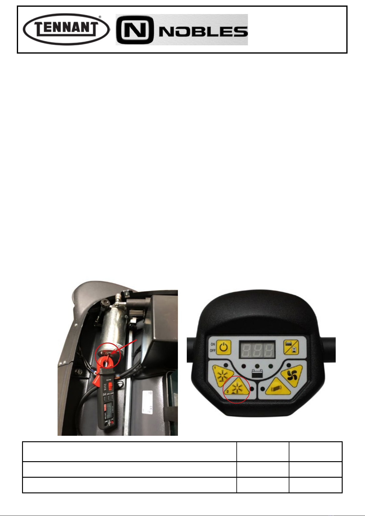
3Use a clamp-on ammeter with a full scale reading of at least 200 A (amperes).
4Move the machine onto a at and smooth oor to ensure a correct current reading.
5Pick out the Red wire of the centre brush motor and apply the clamp-on ammeter to it.
6Run the brush at speed 2, selected by way of the control panel.
7Take note of the reading on the ammeter display and compare it with the values in the table.
8If the value falls within the range indicated in the table, disconnect the instrument and reinstate the top cover of
the machine.
9Conversely, if the value is at variance with those indicated in the table, proceed to make the following checks.
10 Disassemble the side brush and check that the current draw under no-load conditions is within the values in table.
10a
Should the reading indicate a value dierent to those in the table (typically higher), check for wear on the
carbon brushes of the motor, also for wear on the drive belts and cleanliness of the relative pulleys, and
for noise from the pulley bearing.
10b If the reading is within the range of values indicated in the table, check that the brush is not rubbing on the sides
or on the roller, and that there is no abnormal noise coming from the centre brush free wheel bearings.
10c Replace the brush motor with a new one.
Uncouple the side brush to ensure a more accurate reading.
G
6
Current draw A (amperes) Min Max
No load (without brushes) 2.7 A 3.3 A
Load applied (brushes operating) 5.5 A 6.5 A
Carry out the test with the machine at standstill to ensure the brush is not rotated 'against' the
drive, as this could result in a higher current draw reading.
G
5
PLDC04348
REVISION 00
November 09, 2020
TECHNICAL OFFICE
November 30, 2020 8of 58
A1.2 Checking for wear on centre brush drive belt, and replacement
Disassembly
1Move the machine onto at and dry ooring.
2Make sure that there is enough room around the machine to perform the dismantling operations safely.
3If necessary, clean the working area with a jet of compressed air.
4Undo the xing screws of the top cover, and open the cover.
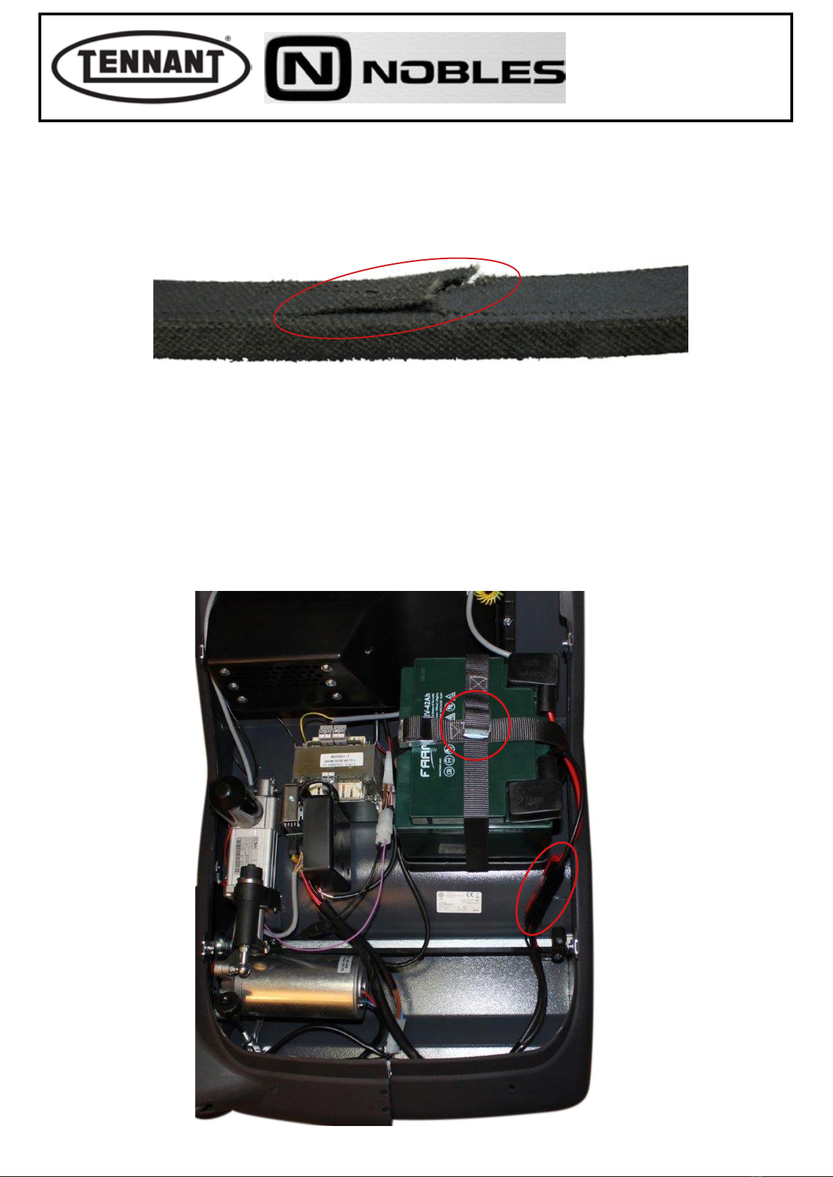
5Disconnect the two connectors (red and black).
6Undo the 2 safety straps securing the battery.
7Remove the battery.
The drive belt will need replacing typically when worn to the point of breaking. However, in
order to avoid machine downtime, it may be useful to replace the belts in advance, before they
break. Belt wear can be seen on the surface in contact with the pulleys, which is smoother and
shows small cracks, as well as by fraying at the top edge of the belt.
i
5 6

PLDC04348
REVISION 00
November 09, 2020
TECHNICAL OFFICE
November 30, 2020 9of 58
Reassembly
1To reassemble, repeat the disassembly operations in reverse order.
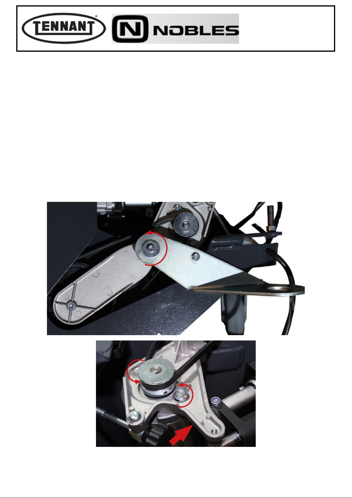
8Loosen the xture of the left hand arm and remove the pivot, then proceed to detach the xture.
9Remove the bush from the left hand arm.
10 Remove the left bottom lateral guard and shift the arm, drawing it way from its usual position.
11 Position the machine on its left hand side and loosen the xture of the right hand arm, removing the pivot so that
the xture can then be detached.
12 Undo the 2 screws of the right lateral guard.
13 Shift the right bottom guard downwards.
14 Check the belt condition.
89
12 13
14
10
PLDC04348
REVISION 00
November 09, 2020
TECHNICAL OFFICE
November 30, 2020 10 of 58
A1.3 Replacing the centre brush transmission belt
Disassembly
1Move the machine onto at and dry ooring.
2Make sure that there is enough room around the machine to perform the dismantling operations safely.
3If necessary, clean the working area with a jet of compressed air.
4Remove the battery.
5Access the belt as explained in the previous heading.
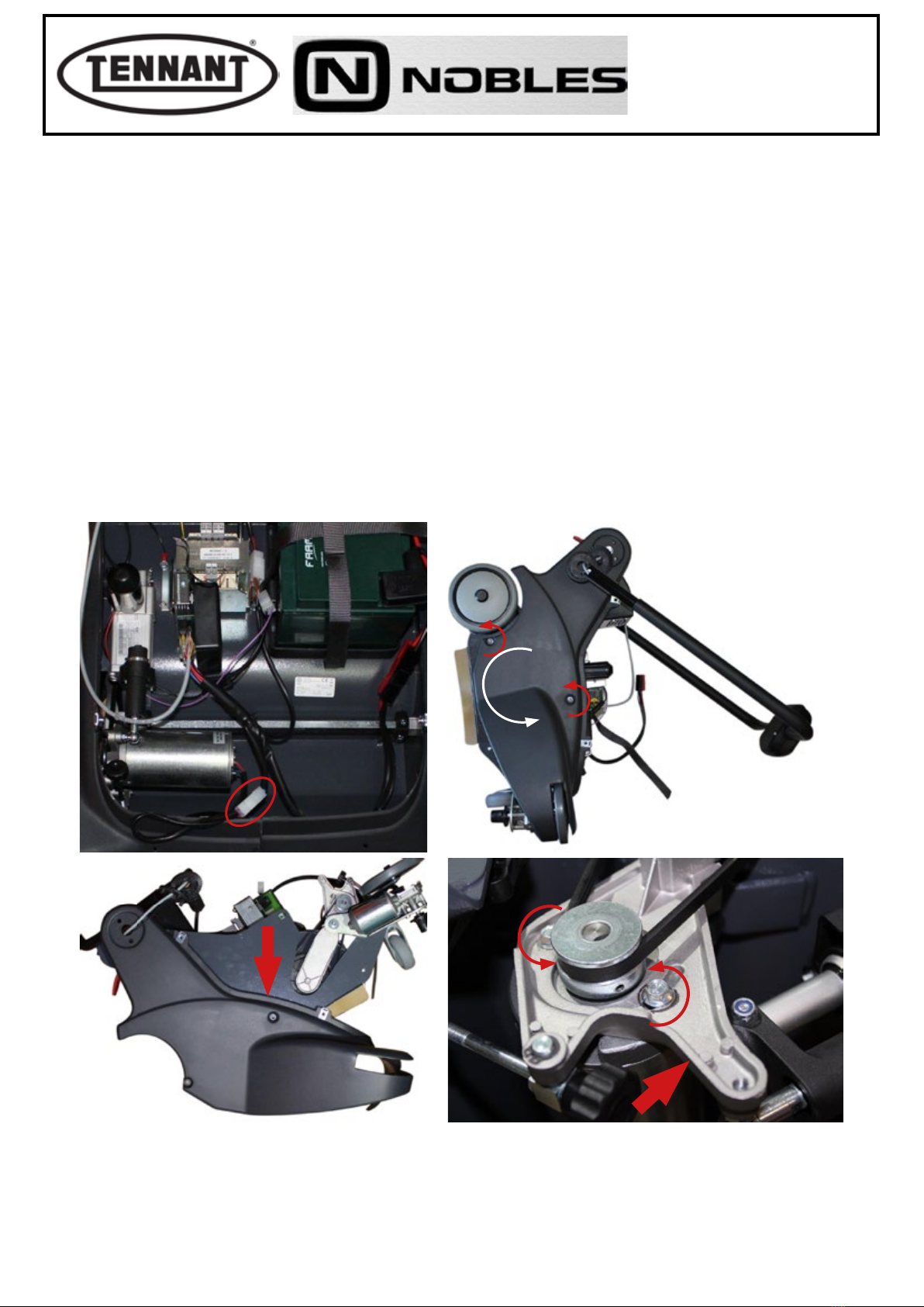
6Remove the side brush motor and loosen the hex head screw to remove the bracket.
7In order to release the belt, the motor pulley must be moved toward the pulley of the centre brush; accordingly,
loosen the two hex head screws and ease the motor toward the brush.
8Remove the belt from the motor pulley, then proceed to unseat it from the pulley of the centre brush. Once the
belt is completely clear of the pulley groove, it can be removed.
Take care when removing and assembling the belt from/onto the pulley; use protective leather
work gloves.
G
Reassembly
1To ret the belt, repeat the disassembly operations described above in reverse order.
7
6

PLDC04348
REVISION 00
November 09, 2020
TECHNICAL OFFICE
November 30, 2020 11 of 58
A1.4 Inspecting and replacing the centre brush motor carbon brushes
Disassembly
1Move the machine onto at and dry ooring.
2Make sure that there is enough room around the machine to perform the dismantling operations safely.
3If necessary, clean the working area with a jet of compressed air, or a vacuum cleaner.
4Remove the battery.
5Identify the white connector of the brush motor and disconnect it.
6Unscrew the two nuts and remove the motor end cap.
7Shift the springs so that the carbon brushes can be removed and their dimensions checked against the measure-
ments indicated.
8Unsolder the carbon brush leads from their respective tags and remove.
To inspect the extent of wear on the carbon brushes and eect their replacement, if necessary,
simply remove the motor end cap.
56
78
G

PLDC04348
REVISION 00
November 09, 2020
TECHNICAL OFFICE
November 30, 2020 12 of 58
Checks
10 Measure the carbon brushes to establish the extent of wear, and compare the values with those illustrated below.
11 The length of the carbon brush must be no less than ≤ 8.3 mm (0.33 inches).
12 In the event that the measurement, even of one carbon brush only, is close to the value indicated as
necessitating replacement, proceed to remove both brushes from the end cap.
13 Even if the carbon brushes appear still to be in good condition, check each one for the state of wear and the inte-
grity of the sliding contact surface, which must present no indications of abnormal wear, or of scorching.
14 Blow the inside of the motor clean with a jet of compressed air, paying particular attention to the area around the
carbon brushes and the rotor where the carbon brushes slide.
15 Check wear in the places where the carbon brushes slide before replacement. A damaged rotor would cause
premature wear of the new carbon brushes.
The carbon brushes must always be replaced as a pair, at one and the same time.
G
Always check that the new carbon brushes are the same shape and
size as those being replaced, apart from the length needless to say,
and that they slide freely in their seats.
G
10
11 10
17.80 ± 0.1 mm
≥ 0.33 in
0,701 ± 0,004 in
≥ 8 . 3 m m
8.70 ± 0.1 mm
0.34 ± 0.004 in
7.70 ± 0.1 mm
0.30 ± 0.004 in

PLDC04348
REVISION 00
November 09, 2020
TECHNICAL OFFICE
November 30, 2020 13 of 58
Reassembly
1Solder the leads of the carbon brushes to the same power supply tags from which the old leads were removed.
2Shift the springs to facilitate the insertion of the new brushes.
3Oer the end cap to the motor frame and slide almost fully into place, then position the springs correctly so that
each one exerts pressure on the relative carbon brush.
4Proceed with reassembly, repeating the steps of the disassembly sequence in reverse order.
1 2
3
PLDC04348
REVISION 00
November 09, 2020
TECHNICAL OFFICE
November 30, 2020 14 of 58
A1.5 Replacing the centre brush motor
Disassembly
1Move the machine onto at and dry ooring.
2Make sure that there is enough room around the machine to perform the dismantling operations safely.
3If necessary, clean the working area with a jet of compressed air, or a vacuum cleaner.
4Remove the battery.
5Identify the white connector of the brush motor and disconnect it.
6Position the machine on its left side and undo the 2 screws of the right lateral guard.
7Shift the right bottom guard downwards.
8Undo the 2 hex head screws securing the motor to the mounting. Shift the motor toward the centre brush so as to
slacken o the drive belt.
9Remove the motor and pulley, separating the belt from the pulley groove.
56
8
7
To free the motor completely, either cut the wires and t two Faston clips for the subsequent
reconnection, or remove the pins directly from the connector.
G
Reassembly
1To reassemble, repeat the disassembly operations in reverse order.
2Remove the pulley from the old motor and t to the replacement motor.
3Apply threadlocker to the 2 screws securing the motor to the mounting. Check that the direction of rotation of the
brush is correct.

PLDC04348
REVISION 00
November 09, 2020
TECHNICAL OFFICE
November 30, 2020 15 of 58
A1.6 Replacement of centre brush
Disassembly
1Move the machine onto at and dry ooring.
2Make sure that there is enough room around the machine to perform the dismantling operations safely.
3If necessary, clean the working area with a jet of compressed air, or a vacuum cleaner.
4Remove the battery.
5Release the xture of the arm on both sides.
6Lay the machine down so that the brush compartment is exposed.
7Turn the brush to the point at which a black key positioned at the left hand end can be seen.
8Depress the black key and push the brush inwards.
9Remove the worn centre brush and proceed to t the new brush, making certain that it is locked in place by the
black key.
The brush will need to be replaced generally as the result of normal wear.
G
8
PLDC04348
REVISION 00
November 09, 2020
TECHNICAL OFFICE
November 30, 2020 16 of 58
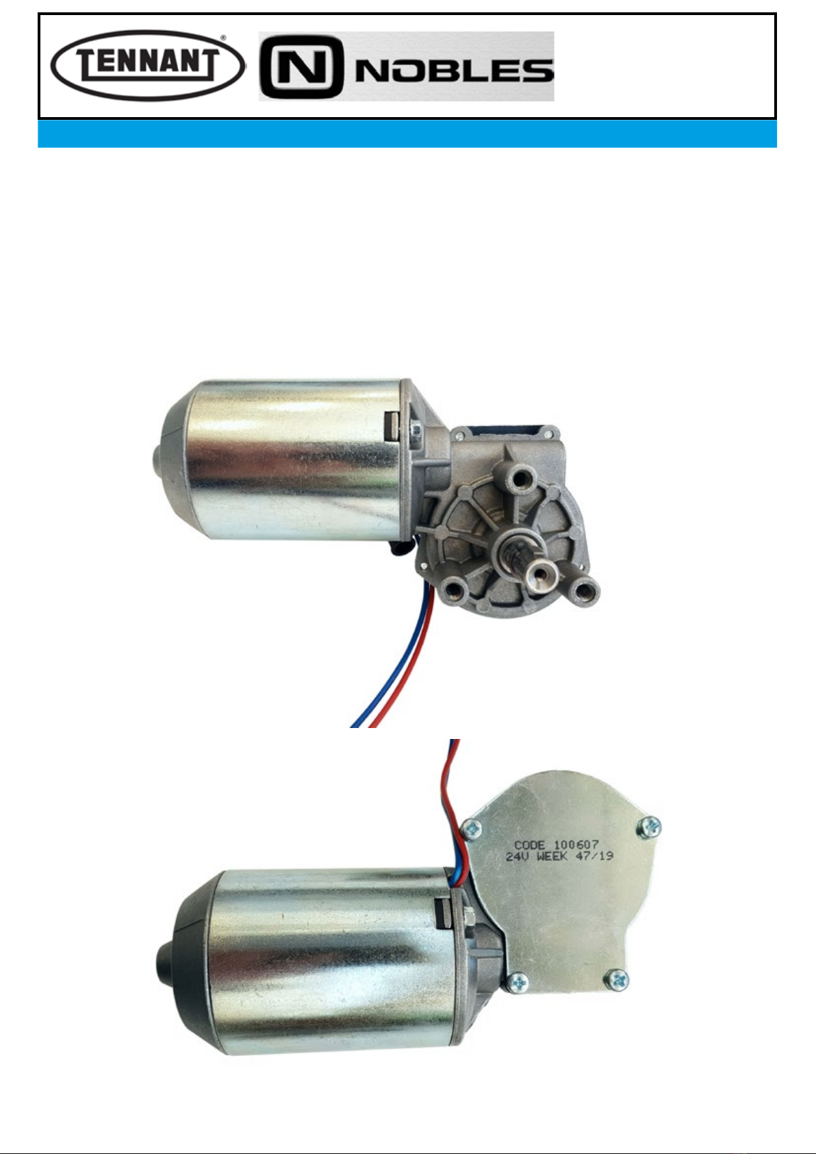
A2 SIDE BRUSH MOTORS
The motor dedicated to the side brush is equipped with a plain angle drive or with a right angle
worm gear unit, the rotor shaft having a double start thread, maximum speed of rotation at the
output shaft 220 rpm. The rated power of the motor is 30W, whilst the voltage is 24 Vdc, albeit
a 12 Vdc input is utilized as in the case of the centre brush motor; in eect, the two motors are
connected together but wired with the polarity of the power cables reversed.
Other specications of the motor are insulation class 'F' and protection IP30 against ingress
of solids and liquids. The motor is equipped with replaceable carbon brushes. With the motor
mounted to the machine, the brush must be driven in rotation anticlockwise, otherwise it will
not operate correctly.
i
PLDC04348
REVISION 00
November 09, 2020
TECHNICAL OFFICE
November 30, 2020 17 of 58
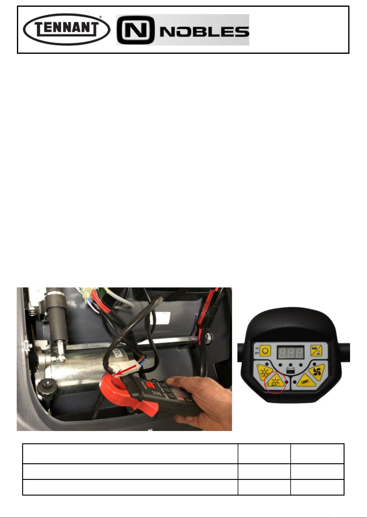
A2.1 Checking the power draw of the side brush motor
1Undo the xing screws of the top cover, and remove the cover.
2Make sure that the batteries on the machine are charged (24 V ± 1 V).
3Use a clamp-on ammeter with a full scale reading of at least 200 A (amperes).
4Move the machine onto a at and smooth oor to ensure a correct current reading.
5Pick out the Red wire of the side brush motor and apply the clamp-on ammeter to it.
6Run the brush at speed 2, selected by way of the control panel.
7Take note of the reading on the ammeter display and compare it with the values in the table.
8If the value falls within the range indicated in the table, disconnect the instrument and reinstate the top cover of
the machine.
9Conversely, if the value is at variance with those indicated in the table, proceed to make the following checks.
10 Disassemble the side brush and check that the current draw under no-load conditions is within the values in
table.
10a Should the reading indicate a value dierent to those in the table (typically higher), check for wear on the carbon
brushes of the motor, and that there is no abnormal noise coming from gear unit.
10b If the reading is within the range of values indicated in the table, check that the brush is not rubbing on the sides.
10c Replace the brush motor with a new one.
Carry out the test with the machine at standstill to ensure the brush is not rotated 'against' the
drive, as this could result in a higher current draw reading.
G
5
6
Current draw A (amperes) Min Max
No load (without brushes) 0.8 A 1.2 A
Load applied (brushes operating) 1 A 1.5 A
Uncouple the centre brush to ensure a more accurate reading.
G
PLDC04348
REVISION 00
November 09, 2020
TECHNICAL OFFICE
November 30, 2020 18 of 58
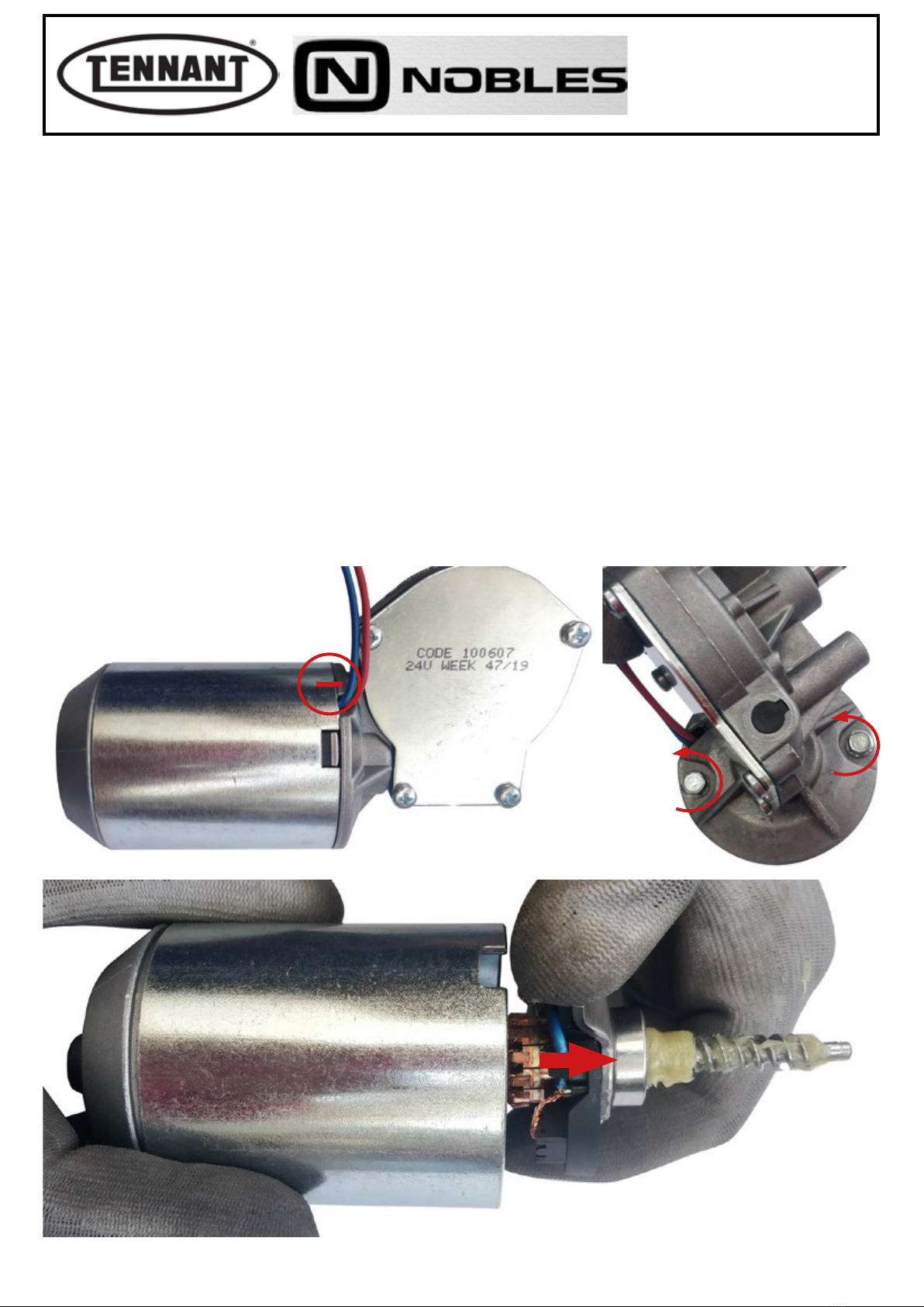
A2.2 Inspecting and replacing the side brush motor carbon brushes
Disassembly
1Move the machine onto at and dry ooring.
2Make sure that there is enough room around the machine to perform the dismantling operations safely.
3Clean the work area thoroughly if need be, either blasting with compressed air or using a vacuum cleaner.
4Remove the battery.
5Shift the right bottom guard downwards.
6Proceed to detach the brush motor as described in the heading below.
7Record the position of the gear unit on the motor by making a witness mark on the end cap.
8Undo the two screws and remove the gear unit.
9Remove the complete rotor assembly.
7 8
9
To inspect the extent of wear on the carbon brushes and eect their replacement, if necessary,
the motor must be removed completely from the machine and disassembled.
G
PLDC04348
REVISION 00
November 09, 2020
TECHNICAL OFFICE
November 30, 2020 19 of 58
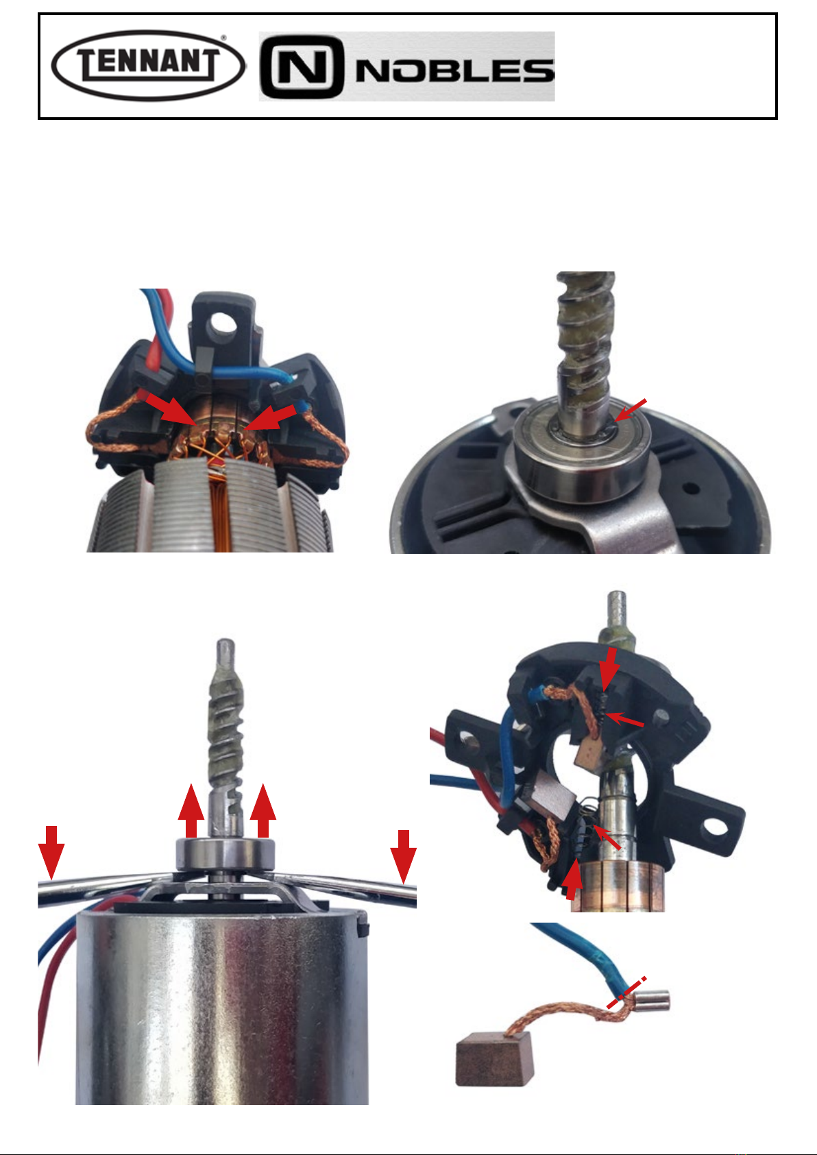
10 Release the power leads from the retainers.
11 Remove the circlip from the face of the bearing.
12 Remove the bearing from its seat, using two screwdrivers as levers to apply pressure from beneath; should the
bearing prove dicult to dislodge from the shaft, use a small puller.
13 Remove the carbon brushes from their slots, taking care not to damage the springs.
14 Cut away a small portion of cable and remove the carbon brushes.
12
13
14
11
10

PLDC04348
REVISION 00
November 09, 2020
TECHNICAL OFFICE
November 30, 2020 20 of 58
Checks
14 Measure the carbon brushes to establish the extent of wear, and compare the values with those illustrated below.
15 The length of the carbon brush must be no less than ≤ 4.7 mm (0.19 inches).
16 In the event that the measurement, even of one carbon brush only, is close to the value indicated as necessita-
ting replacement, proceed to detach the brushes from the power leads.
17 If the carbon brushes appear still to be in good condition, check each one for the state of wear and the integrity of
the sliding contact surface, which must present no indications of abnormal wear, or of scorching.
18 Blow the inside of the motor clean with a jet of compressed air, paying particular attention to the area around the
carbon brushes and the rotor where the carbon brushes slide.
19 Check wear in the places where the carbon brushes slide before replacement. A damaged rotor would cause
premature wear of the new carbon brushes.
The carbon brushes must always be replaced as a pair, at one and the same time.
G
Always check that the new carbon brushes are the same shape and size as those being
replaced (naturally apart from the length) and that they slide freely in their seats.
G
9.80 ± 0.1 mm
≥ 0.19 in
0,385 ± 0,004 in
≥ 4 . 7 m m
8.70 ± 0.1 mm
0.34 ± 0.004 in
7.70 ± 0.1 mm
0.30 ± 0.004 in
14 14
15
This manual suits for next models
1
Table of contents
Popular Floor Machine manuals by other brands

Kärcher
Kärcher BD 30/4C user manual

Windsor
Windsor CVC24 operating instructions

Minuteman
Minuteman Mirage M220021K17 Operation service parts care

Nilfisk-Advance
Nilfisk-Advance BU800 51BT Instructions for use

HTC
HTC Desire 650 Service manual

U.S. Products
U.S. Products Agitator 20 Information & operating instructions

Viper
Viper CEX410 Use and maintenance

Tornado Karcher
Tornado Karcher EB 30/1 manual

Advance acoustic
Advance acoustic SW8000 Instructions for use

Topfloor
Topfloor TF100R-TRS Operator's manual

Kärcher
Kärcher KM 150/500 R LPG manual

Jon-Don
Jon-Don PE500 Safety, operation and maintenance manual with parts list


