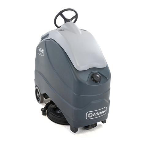
Crescent SC500 User manual

SC500
www.crescentindustrial.co.uk
Service
Manual

Contents iiService Manual – SC500
Contents
03 - General Information. . . . . . . . . . . . . . . . . . . . . . . . . . . . . . . . . . . 6
Machine General Description . . . . . . . . . . . . . . . . . . . . . . . . . . . . . . . . 6
Service Manual Purpose and Field of Application . . . . . . . . . . . . . . . . . . . . . 6
Other Reference Manuals . . . . . . . . . . . . . . . . . . . . . . . . . . . . . . . . . . 6
Conventions . . . . . . . . . . . . . . . . . . . . . . . . . . . . . . . . . . . . . . . . . 7
Name Plate . . . . . . . . . . . . . . . . . . . . . . . . . . . . . . . . . . . . . . . . . . 7
Safety . . . . . . . . . . . . . . . . . . . . . . . . . . . . . . . . . . . . . . . . . . . . . 8
Visible Symbols on the Machine . . . . . . . . . . . . . . . . . . . . . . . . . . . . 8
Symbols. . . . . . . . . . . . . . . . . . . . . . . . . . . . . . . . . . . . . . . . . . 8
General Safety Instructions . . . . . . . . . . . . . . . . . . . . . . . . . . . . . . 9
Lifting The Machine . . . . . . . . . . . . . . . . . . . . . . . . . . . . . . . . . . . . . 12
Transporting The Machine . . . . . . . . . . . . . . . . . . . . . . . . . . . . . . . . .12
Technical Specications . . . . . . . . . . . . . . . . . . . . . . . . . . . . . . . . . . .13
Maintenance Schedule . . . . . . . . . . . . . . . . . . . . . . . . . . . . . . . . . . . .15
Know Your Machine . . . . . . . . . . . . . . . . . . . . . . . . . . . . . . . . . . . . . 16
Control panel Disc deck (Prod. Nr.: 9087352020, 9087354020, 9087350020, 9087351020)
16
Control panel REV deck (Prod. Nr.: 9087353020, 9087355020) . . . . . . . . . . . . 16
Control panel Disc deck (Prod. Nr.: 9087403020, 9087404020, 9087400020,9087401020)
17
Control panel REV deck (Prod. Nr.: 9087405020, 9087402020) . . . . . . . . . . . . 17
Service and Diagnostic Equipment . . . . . . . . . . . . . . . . . . . . . . . . . . . . . 20
Dimensions . . . . . . . . . . . . . . . . . . . . . . . . . . . . . . . . . . . . . . . . . .21
SC500 Disc . . . . . . . . . . . . . . . . . . . . . . . . . . . . . . . . . . . . . . . . 21
SC500 REV. . . . . . . . . . . . . . . . . . . . . . . . . . . . . . . . . . . . . . . .22
04 - Control System . . . . . . . . . . . . . . . . . . . . . . . . . . . . . . . . . . . . . 23
Product Nr.: 9087352020, 9087354020, 9087350020, 9087351020, 9087353020, 9087355020
23
Functional Description. . . . . . . . . . . . . . . . . . . . . . . . . . . . . . . . . . . .23
Wiring Diagram . . . . . . . . . . . . . . . . . . . . . . . . . . . . . . . . . . . . . . .24
Component Locations . . . . . . . . . . . . . . . . . . . . . . . . . . . . . . . . . . . . 25
Troubleshooting . . . . . . . . . . . . . . . . . . . . . . . . . . . . . . . . . . . . . . . 26
Main machine controller (EB1) Alarm Codes. . . . . . . . . . . . . . . . . . . . . .26
Black-box: Recording of Alarms, Parameters (see pages 34-35), Partial Operating Time
Counter. . . . . . . . . . . . . . . . . . . . . . . . . . . . . . . . . . . . . . . . .31
Display, Main Screen . . . . . . . . . . . . . . . . . . . . . . . . . . . . . . . . . .31
Display, Alarms Log Screen . . . . . . . . . . . . . . . . . . . . . . . . . . . . . . .32
Display, Machine Settings Screen . . . . . . . . . . . . . . . . . . . . . . . . . . . 33
Display, Operating Time Counter Screen. . . . . . . . . . . . . . . . . . . . . . . .35
System for Flow Rate Regulation as Function of Speed . . . . . . . . . . . . . . . . 36
Removal and Installation . . . . . . . . . . . . . . . . . . . . . . . . . . . . . . . . . . 37
Main machine controller (EB1) . . . . . . . . . . . . . . . . . . . . . . . . . . . . . 37
Display Controller (EB2) and User interface controller (EB3) . . . . . . . . . . . . 39
Specications . . . . . . . . . . . . . . . . . . . . . . . . . . . . . . . . . . . . . . . . .41
Main machine controller (EB1) Connectors . . . . . . . . . . . . . . . . . . . . . . 41
Connectors of the Display Controller (EB2) . . . . . . . . . . . . . . . . . . . . . . 47
Shop Measurements . . . . . . . . . . . . . . . . . . . . . . . . . . . . . . . . . . . . . 49
Shop Measurements - Main machine controller (EB1) . . . . . . . . . . . . . . . . 49
Shop Measurements - Display Controller (EB2) . . . . . . . . . . . . . . . . . . . . 56

Contents iiiService Manual – SC500
05 - Control System, Magnetic Smart Key . . . . . . . . . . . . . . . . . . . . . . . . 60
Product Nr.: 9087403020, 9087404020, 9087400020,9087401020, 9087405020, 9087402020
60
Functional Description. . . . . . . . . . . . . . . . . . . . . . . . . . . . . . . . . . . .60
Wiring Diagram . . . . . . . . . . . . . . . . . . . . . . . . . . . . . . . . . . . . . . . 61
Component Locations . . . . . . . . . . . . . . . . . . . . . . . . . . . . . . . . . . . . 62
Troubleshooting . . . . . . . . . . . . . . . . . . . . . . . . . . . . . . . . . . . . . . . 63
Main machine controller (EB1) Alarm Codes. . . . . . . . . . . . . . . . . . . . . .63
Black-box: Recording of Alarms, Parameters (see pages 71-72), Partial Operating Time
Counter. . . . . . . . . . . . . . . . . . . . . . . . . . . . . . . . . . . . . . . . .68
Display, Main Screen . . . . . . . . . . . . . . . . . . . . . . . . . . . . . . . . . . 68
Display, Alarms Log Screen . . . . . . . . . . . . . . . . . . . . . . . . . . . . . . .69
Display, Machine Settings Screen . . . . . . . . . . . . . . . . . . . . . . . . . . . 70
Display, Operating Time Counter Screen. . . . . . . . . . . . . . . . . . . . . . . .73
Display, Magnetic Smart Keys Management Screen. . . . . . . . . . . . . . . . . .74
System for Flow Rate Regulation as Function of Speed . . . . . . . . . . . . . . . . 75
Removal and Installation . . . . . . . . . . . . . . . . . . . . . . . . . . . . . . . . . . 76
Main machine controller (EB1) . . . . . . . . . . . . . . . . . . . . . . . . . . . . . 76
Display Controller (EB2), User interface controller (EB3) and Smart Key Reader (IB)78
Specications . . . . . . . . . . . . . . . . . . . . . . . . . . . . . . . . . . . . . . . . .80
Main machine controller (EB1) Connectors . . . . . . . . . . . . . . . . . . . . . . 80
Connectors of the Display Controller (EB2) . . . . . . . . . . . . . . . . . . . . . . 86
Shop Measurements . . . . . . . . . . . . . . . . . . . . . . . . . . . . . . . . . . . . . 89
Shop Measurements - Main machine controller (EB1) . . . . . . . . . . . . . . . . 89
Shop Measurements - Display Controller (EB2) . . . . . . . . . . . . . . . . . . . . 96
10 - Chassis System . . . . . . . . . . . . . . . . . . . . . . . . . . . . . . . . . . . . . 100
Chassis (main parts) . . . . . . . . . . . . . . . . . . . . . . . . . . . . . . . . . . . . 100
20 - Wheel System, Traction . . . . . . . . . . . . . . . . . . . . . . . . . . . . . . . .101
Functional Description. . . . . . . . . . . . . . . . . . . . . . . . . . . . . . . . . . .101
Wiring Diagram . . . . . . . . . . . . . . . . . . . . . . . . . . . . . . . . . . . . . . 102
Component Locations . . . . . . . . . . . . . . . . . . . . . . . . . . . . . . . . . . . 103
Troubleshooting . . . . . . . . . . . . . . . . . . . . . . . . . . . . . . . . . . . . . . 105
Drive System Gear Motor Current Draw Test . . . . . . . . . . . . . . . . . . . . 106
Removal and Installation . . . . . . . . . . . . . . . . . . . . . . . . . . . . . . . . . 107
Speed Potentiometer. . . . . . . . . . . . . . . . . . . . . . . . . . . . . . . . . .107
Specications . . . . . . . . . . . . . . . . . . . . . . . . . . . . . . . . . . . . . . . .108
24 - Electrical System. . . . . . . . . . . . . . . . . . . . . . . . . . . . . . . . . . . .109
Functional Description. . . . . . . . . . . . . . . . . . . . . . . . . . . . . . . . . . .109
Battery Charger . . . . . . . . . . . . . . . . . . . . . . . . . . . . . . . . . . . . 109
Battery Charge State Display . . . . . . . . . . . . . . . . . . . . . . . . . . . . 110
Wiring Diagram . . . . . . . . . . . . . . . . . . . . . . . . . . . . . . . . . . . . . . 111
Component Locations . . . . . . . . . . . . . . . . . . . . . . . . . . . . . . . . . . . 112
Maintenance and Adjustments . . . . . . . . . . . . . . . . . . . . . . . . . . . . . . 113
Setting the Installed Battery Type . . . . . . . . . . . . . . . . . . . . . . . . . . 113
Battery installation . . . . . . . . . . . . . . . . . . . . . . . . . . . . . . . . . . 114
Battery Charging . . . . . . . . . . . . . . . . . . . . . . . . . . . . . . . . . . . 115
Checking/Replacing Fuses. . . . . . . . . . . . . . . . . . . . . . . . . . . . . . .116
Troubleshooting . . . . . . . . . . . . . . . . . . . . . . . . . . . . . . . . . . . . . . 118
General Wiring Diagram (Product Nr.: 9087352020, 9087354020, 9087350020, 9087351020,
9087353020, 9087355020) . . . . . . . . . . . . . . . . . . . . . . . . . . . . . . . . . 119
General Wiring Diagram (Product Nr.: 9087403020, 9087404020, 9087400020,9087401020,
9087405020, 9087402020) . . . . . . . . . . . . . . . . . . . . . . . . . . . . . . . . . 120
Specications . . . . . . . . . . . . . . . . . . . . . . . . . . . . . . . . . . . . . . . .121

Contents ivService Manual – SC500
30 - Solution System . . . . . . . . . . . . . . . . . . . . . . . . . . . . . . . . . . . . 122
Functional Description. . . . . . . . . . . . . . . . . . . . . . . . . . . . . . . . . . .122
Water Level Sensor Operation . . . . . . . . . . . . . . . . . . . . . . . . . . . . 123
Wiring Diagram . . . . . . . . . . . . . . . . . . . . . . . . . . . . . . . . . . . . . . 124
Component Locations . . . . . . . . . . . . . . . . . . . . . . . . . . . . . . . . . . . 125
Maintenance and Adjustments . . . . . . . . . . . . . . . . . . . . . . . . . . . . . . 127
Cleaning the Detergent Solution Tank and Filter . . . . . . . . . . . . . . . . . . 127
Cleaning the EcoFlex Detergent Tank . . . . . . . . . . . . . . . . . . . . . . . . 128
Draining the EcoFlex System . . . . . . . . . . . . . . . . . . . . . . . . . . . . . 129
Troubleshooting . . . . . . . . . . . . . . . . . . . . . . . . . . . . . . . . . . . . . . 130
Removal and Installation . . . . . . . . . . . . . . . . . . . . . . . . . . . . . . . . . 132
Solenoid Valve . . . . . . . . . . . . . . . . . . . . . . . . . . . . . . . . . . . . . 132
Detergent Pump (Piston Pump) . . . . . . . . . . . . . . . . . . . . . . . . . . . .133
Detergent Pump (Peristaltic Pump) . . . . . . . . . . . . . . . . . . . . . . . . . 134
Checking the Water Level Sensor Operation . . . . . . . . . . . . . . . . . . . . . 135
Water Level Sensor . . . . . . . . . . . . . . . . . . . . . . . . . . . . . . . . . . 136
Specications . . . . . . . . . . . . . . . . . . . . . . . . . . . . . . . . . . . . . . . .137
34 - Scrub System, Disc. . . . . . . . . . . . . . . . . . . . . . . . . . . . . . . . . . .138
Functional Description. . . . . . . . . . . . . . . . . . . . . . . . . . . . . . . . . . .138
Brush Release System . . . . . . . . . . . . . . . . . . . . . . . . . . . . . . . . .138
Wiring Diagram . . . . . . . . . . . . . . . . . . . . . . . . . . . . . . . . . . . . . . 139
Brush Deck Actuator System . . . . . . . . . . . . . . . . . . . . . . . . . . . . . . . 140
Component Locations . . . . . . . . . . . . . . . . . . . . . . . . . . . . . . . . . . . 141
Maintenance and Adjustments . . . . . . . . . . . . . . . . . . . . . . . . . . . . . . 143
Brush Installation/Removal . . . . . . . . . . . . . . . . . . . . . . . . . . . . . .143
Troubleshooting . . . . . . . . . . . . . . . . . . . . . . . . . . . . . . . . . . . . . . 144
Brush Motor Current Draw Test . . . . . . . . . . . . . . . . . . . . . . . . . . . 145
Removal and Installation . . . . . . . . . . . . . . . . . . . . . . . . . . . . . . . . . 146
Brush Deck . . . . . . . . . . . . . . . . . . . . . . . . . . . . . . . . . . . . . . .146
Checking/Replacing Brush Motor Carbon Brushes . . . . . . . . . . . . . . . . . 149
Brush Motor Disassembly/Assembly . . . . . . . . . . . . . . . . . . . . . . . . . 150
Brush Deck Actuator . . . . . . . . . . . . . . . . . . . . . . . . . . . . . . . . . 151
Specications . . . . . . . . . . . . . . . . . . . . . . . . . . . . . . . . . . . . . . . . . .
34 - Scrub System, REV . . . . . . . . . . . . . . . . . . . . . . . . . . . . . . . . . . 152
Functional Description. . . . . . . . . . . . . . . . . . . . . . . . . . . . . . . . . . .152
Wiring Diagram . . . . . . . . . . . . . . . . . . . . . . . . . . . . . . . . . . . . . . 153
Brush Deck Actuator System . . . . . . . . . . . . . . . . . . . . . . . . . . . . . . . 154
Component Locations . . . . . . . . . . . . . . . . . . . . . . . . . . . . . . . . . . . 155
Maintenance and Adjustments . . . . . . . . . . . . . . . . . . . . . . . . . . . . . . 157
Brush Installation/Removal . . . . . . . . . . . . . . . . . . . . . . . . . . . . . .157
Troubleshooting . . . . . . . . . . . . . . . . . . . . . . . . . . . . . . . . . . . . . . 158
REV Motor Current Draw Test . . . . . . . . . . . . . . . . . . . . . . . . . . . . 159
Removal and Installation . . . . . . . . . . . . . . . . . . . . . . . . . . . . . . . . . 160
REV Deck . . . . . . . . . . . . . . . . . . . . . . . . . . . . . . . . . . . . . . . 160
Checking/Replacing REV Motor Carbon Brushes . . . . . . . . . . . . . . . . . . 162
Brush Deck Actuator . . . . . . . . . . . . . . . . . . . . . . . . . . . . . . . . . 165
Specications . . . . . . . . . . . . . . . . . . . . . . . . . . . . . . . . . . . . . . . .166

Contents vService Manual – SC500
38 - Squeegee System . . . . . . . . . . . . . . . . . . . . . . . . . . . . . . . . . . . .167
Functional Description. . . . . . . . . . . . . . . . . . . . . . . . . . . . . . . . . . .167
Component Locations . . . . . . . . . . . . . . . . . . . . . . . . . . . . . . . . . . . 168
Maintenance and Adjustments . . . . . . . . . . . . . . . . . . . . . . . . . . . . . . 169
Squeegee cleaning . . . . . . . . . . . . . . . . . . . . . . . . . . . . . . . . . . . 169
Checking/Replacing the Squeegee Blades . . . . . . . . . . . . . . . . . . . . . . 170
Troubleshooting . . . . . . . . . . . . . . . . . . . . . . . . . . . . . . . . . . . . . . 171
Removal and Installation . . . . . . . . . . . . . . . . . . . . . . . . . . . . . . . . . 172
Gas Spring on the Squeegee Support . . . . . . . . . . . . . . . . . . . . . . . . . 172
Spring on the Squeegee Support . . . . . . . . . . . . . . . . . . . . . . . . . . . 173
Specications . . . . . . . . . . . . . . . . . . . . . . . . . . . . . . . . . . . . . . . .174
40 - Recovery System . . . . . . . . . . . . . . . . . . . . . . . . . . . . . . . . . . . .175
Functional Description. . . . . . . . . . . . . . . . . . . . . . . . . . . . . . . . . . .175
Wiring Diagram . . . . . . . . . . . . . . . . . . . . . . . . . . . . . . . . . . . . . . 176
Component Locations . . . . . . . . . . . . . . . . . . . . . . . . . . . . . . . . . . . 177
Maintenance and Adjustments . . . . . . . . . . . . . . . . . . . . . . . . . . . . . . 178
Recovery Tank Cleaning. . . . . . . . . . . . . . . . . . . . . . . . . . . . . . . .178
Troubleshooting . . . . . . . . . . . . . . . . . . . . . . . . . . . . . . . . . . . . . . 179
Vacuum Motor Current Draw Test . . . . . . . . . . . . . . . . . . . . . . . . . . 180
Removal and Installation . . . . . . . . . . . . . . . . . . . . . . . . . . . . . . . . . 181
Vacuum Motor Unit . . . . . . . . . . . . . . . . . . . . . . . . . . . . . . . . . . 181
Container and Vacuum Motor Disassembly/Assembly. . . . . . . . . . . . . . . . 182
Specications . . . . . . . . . . . . . . . . . . . . . . . . . . . . . . . . . . . . . . . .185
90 - Options . . . . . . . . . . . . . . . . . . . . . . . . . . . . . . . . . . . . . . . . . 186

6Service Manual – SC500
03 - General Information
Machine General Description
The SC500 is a “walk-behind” industrial machine designed to wash and dry oors in one pass. The machine
is powered by on-board batteries, models can be equipped with EcoFlex system. The machine features
variable oor pressure disc brush or REV system, controlled detergent solution dosing and a rear squeegee
with rubber blades that vacuums and dries the oor.
Service Manual Purpose and Field of Application
The Service Manual is a technical resource intended to help service technicians when carrying out
maintenance and repairs on the SC500, to guarantee the best cleaning performance and a long working life
for the machine.
Please read this manual carefully before performing any maintenance and repair procedure on the machine.
Other Reference Manuals
Model Product Nr. Instructions for use Spare Parts List
Advance SC500 X20 B 9087352020
9099980000 9099981000
Advance SC500 X20R B 9087353020
Advance SC500 20D B 9087354020
Advance SC500 X20 B V 9087403020
Advance SC500 X20R B V 9087405020
Advance SC500 20D B V 9087404020
Nilsk SC500 53 B FULL PKG 9087350020
9099974000 9099975000
Nilsk SC500 53 B 9087351020
Nilsk SC500 53R B 9087355020
Nilsk SC500 53 B FULL PKG V 9087400020
Nilsk SC500 53 B V 9087401020
Nilsk SC500 53R B V 9087402020
Assembly Instructions Instruction Code Machines concerned
EcoFlex Kit 9100000923 SC500 Nilsk
Battery charger kit 9100000924 SC500 Nilsk
Vacuum system motor kit 9100000753 All SC500
TrackClean 9100000057 All SC500
These manuals are available at:
• Local Advance or Nilsk retailer
• Advance website: www.advance-us.com
• Nilsk website: www.nilsk.com
• EZ-Data application

7Service Manual – SC500 03 - General Information
Conventions
Forward, backward, front, rear, left or right are intended with reference to the operator’s position, that is to
say in driving position.
Name Plate
Reference to Figure 1
The machine serial number and model name
are marked on the plate (see the example to the
side).
Product code and year of production (Date code:
A17, as January 2017) are marked on the same
plate.
Model: Scrubber-Dryer SC500 20 B
Prod. Nr: 9087352020
GVW: 207 kg/456 lb
Battery 24 Vdc
21 A Charg.100-240Vac 50-60 Hz
Type E Scrubber Dryer
Serial No: ..................
Date code: .......
LpA = 63 dB(A)
IPX4
2%
“Made in Hungary”
Nilfisk-Advance, Inc.
Plymouth, MN, USA
www.advance-us.com
UL 583
CSA C22.2 N.68-92
A Nilfisk-Advance Brand
3084826
Figure 1:

8Service Manual – SC500 03 - General Information
Safety
The following symbols indicate potentially dangerous situations. Always read this information carefully and
take all necessary precautions to safeguard people and property.
Visible Symbols on the Machine
WARNING: Carefully read all the instructions before performing any operation on the
machine.
WARNING: Do not wash the machine with direct or pressurized water jets.
max.2%
WARNING: Do not use the machine on slopes with a gradient exceeding the
specications.
Symbols
The following symbols are used to help you recognize the information concerning the safety and the
prevention of problems.
DANGER: Indicates a potentially hazardous situation which, if not avoided, will result in death or
serious injury.
WARNING: Indicates a potentially hazardous situation which, if not avoided, could result in death
or serious injury.
CAUTION: Indicates a potentially hazardous situation which, if not avoided, could result in minor
or moderate injury.
Note: Indicates an important informational message.

9Service Manual – SC500 03 - General Information
General Safety Instructions
Specic warnings and cautions to inform about potential damages to people and machine are shown below.
DANGER: Before performing any maintenance, repair, cleaning or replacement procedure,
remove the ignition key and disconnect the battery connector).
−This machine must be used by properly trained operators only.
−Do not wear jewels when working near electrical components.
−Do not work under the lifted machine without supporting it with safety stands.
−Do not operate the machine near toxic, dangerous, ammable and/or explosive
powders, liquids or vapors: This machine is not suitable for collecting dangerous
powders.
−When using lead (WET) batteries, keep sparks, ames and smoking materials away
from the batteries. During the normal operation explosive gases are released.
−When using lead (WET) batteries, battery charging produces highly explosive
hydrogen gas. During battery charging, lift the recovery tank and perform this
procedure in well-ventilated areas and away from naked ames.
CAUTION: Carefully read all the instructions before performing any maintenance/repair procedure.
−The machine ignition key has a built-in magnet. Do not place objects having magnetic
bands (such as credit cards, electronic keys, phone cards) near the key. The built-in
magnet can damage or erase the data stored on the magnetic bands.
−Before using the battery charger, ensure that frequency and voltage values, indicated
on the machine serial number plate, match the electrical mains voltage.
−Do not pull or carry the machine by the battery charger cable and never use the battery
charger cable as a handle. Do not close a door on the battery charger cable, or pull the
battery charger cable around sharp edges or corners. Do not run the machine on the
battery charger cable.
−Keep the battery charger cable away from heated surfaces.
−Do not charge the batteries if the battery charger cable or the plug are damaged.
−To reduce the risk of re, electric shock, or injury, do not leave the machine
unattended when it is plugged in. Before performing any maintenance procedure,
disconnect the battery charger cable from the electrical mains.
−Do not smoke while charging the batteries.
−To avoid any unauthorized use of the machine, remove the ignition key.
−Do not leave the machine unattended without being sure that it cannot move
independently.
−Always protect the machine against the sun, rain and bad weather, both under
operation and inactivity condition. Store the machine indoors, in a dry place: This
machine must be used in dry conditions, it must not be used or kept outdoors in wet
conditions.
−Before using the machine, close all doors and/or covers as shown in the User Manual.

10Service Manual – SC500 03 - General Information
−This machine is not intended for use by persons (including children) with reduced
physical, sensory or mental capabilities, or lack of experience and knowledge, unless
they have been given supervision or instruction concerning use of the machine by a
person responsible for they safety.
−Children should be supervised to ensure that they do not play with the machine.
−Close attention is necessary when used near children. Use only as shown in this
Manual. Use only Nilsk or Advance recommended accessories.
−Check the machine carefully before each use, always check that all the components
have been properly assembled before use. If the machine is not perfectly assembled it
can cause damages to people and properties.
−Take all necessary precautions to prevent hair, jewels and loose clothes from being
caught by the machine moving parts.
−Do not use the machine on incline.
−Do not tilt the machine more than the angle indicated on the machine itself, in order to
prevent instability.
−Do not use the machine in particularly dusty areas.
−Use the machine only where a proper lighting is provided.
−While using this machine, take care not to cause damage to people or objects.
−Do not bump into shelves or scaffoldings, especially where there is a risk of falling
objects.
−Do not lean liquid containers on the machine, use the relevant can holder.
−The machine operating temperature must be between 32°F and 104°F (0°C and +40°C).
−The machine storage temperature must be between 32°F and 104°F (0°C and +40°C).
−The humidity must be between 30% and 95%.
−When using oor cleaning detergents, follow the instructions on the labels of the
detergent bottles.
−To handle oor cleaning detergents, wear suitable gloves and protections.
−Do not use the machine as a means of transport.
−Do not allow the brush/pad to operate while the machine is stationary to avoid
damaging the oor.
−In case of re, use a powder re extinguisher, not a water one.
−Do not tamper with the machine safety guards and follow the ordinary maintenance
instructions scrupulously.
−Do not allow any object to enter into the openings. Do not use the machine if the
openings are clogged. Always keep the openings free from dust, hairs and any other
foreign material which could reduce the air ow.
−Do not remove or modify the plates afxed to the machine.
−When the machine is to be pushed for service reasons (missing or discharged
batteries, etc.), the speed must not exceed 2.5 mi/h (4 km/h).

11Service Manual – SC500 03 - General Information
−This machine cannot be used on roads or public streets.
−Pay attention during machine transportation when temperature is below freezing point.
The water in the recovery tank or in the hoses could freeze and seriously damage the
machine.
−Use brushes and pads supplied with the machine or those specied in the User
Manual. Using other brushes or pads could reduce safety.
−In case of machine malfunctions, ensure that these are not due to lack of maintenance.
If necessary, request assistance from the authorised personnel or from an authorised
Service Center.
−If parts must be replaced, require ORIGINAL spare parts from an Authorised Dealer or
Retailer.
−To ensure machine proper and safe operation, the scheduled maintenance shown in
the relevant chapter of this Manual, must be performed by the authorised personnel or
by an authorised Service Center.
−Do not wash the machine with direct or pressurised water jets, or with corrosive
substances.
−The machine must be disposed of properly, because of the presence of toxic-harmful
materials (batteries, etc.), which are subject to standards that require disposal in
special centres.

12Service Manual – SC500 03 - General Information
Lifting The Machine
WARNING: Do not work under the lifted machine without supporting it with safety stands.
Transporting The Machine
WARNING: Before transporting the machine, make sure that:
−All covers are closed.
−The recovery tank and the detergent tank are empty.
−The batteries are disconnected.
−The ignition key is removed.
−The machine is securely fastened to the means of transport.

13Service Manual – SC500 03 - General Information
Technical Specications
Description / Model SC500
DISC REV
Solution tank capacity 12 US gal (45 liters)
Recovery tank capacity 12 US gal (45 liters)
Machine length 50.3 in (1277 mm) 51.2 in (1302 mm)
Machine width with squeegee 28.3 in (720 mm)
Machine width without squeegee 21 in (532 mm) 21.2 in (538 mm)
Machine height 41.8 in (1063 mm)
Cleaning width 20 in (530 mm)
Driving wheel diameter 7.8 in (200 mm)
Driving wheel specic pressure on the oor (*) 101 psi (0.7 N/mm2)
Rear wheel diameter 3.1 in (80 mm)
Rear wheel specic pressure on the oor (*) 304 psi (2.1 N/mm2)
Brush/pad diameter 20 in (530/508 mm)
Brush pressure with extra-pressure function turned off 33 lb (15 kg) 49 lb (22 kg)
Brush pressure with extra-pressure function turned on 66 lb (30 kg) 66 lb (30 kg)
Solution ow values
0.75 cl/m / 1.5 cl/m
3.0 cl/m / 2.8 l/min
0.38 cl/m / 0.75 cl/m
1.5 cl/m / 2.8 l/min
EcoFlex system detergent percentage Ratio 1:400 ÷ 1:33 (0.25% ÷ 3%)
Sound pressure level at workstation (ISO 11201, ISO 4871,
EN 60335-2-72) (LpA) 63 ± 3 dB(A) 65 ± 3 dB(A)
Sound pressure level at workstation in silent mode (LpA) 60 ± 3 dB(A) 61 ± 3 dB(A)
Machine sound power level (ISO 3744, ISO 4871, EN
60335-2-72) (LwA) 81 dB(A) 83 dB(A)
Vibration level at the operator’s arms (ISO 5349-1, EN
60335-2-72) < 98.4 in/s2 (< 2.5 m/s2)
Maximum gradient when working 2%
Drive system motor power 0.27 hp (200 W)
Drive speed (variable) 0 - 3.1 mi/h (0 - 5 km/h)
Vacuum system motor power 0.37 hp (280 W)
Vacuum system circuit capacity 29.9 in H2O (760 mm H2O)
Brush motor power 0.6 hp (450 W) 0.9 HP (670 W)
Brush rotation speed 155 rpm -
Total power draw (EN 60335-2-72) 0.7 hp (500 W)
IP protection class X4
Protection class (electric) III (I for the battery charger)

14Service Manual – SC500 03 - General Information
Description / Model SC500
DISC REV
Battery compartment size 13.7x13.7x10.2 in (350x350x260 mm)
System voltage 24V
Standard batteries (2) 12V 105 AhC5
Battery charger 24V 13A
Operating time (standard batteries) (EN 60335-2-72) 3.5 hour
Weight without batteries and with empty tanks 187 lb (85 kg) 194 lb (88 kg)
Gross vehicle weight (GVW) 456 lb (207 kg) 463 lb (210 kg)
Shipping weight 256 lb (116 kg) 262 lb (119 kg)
(*) Machines have been tested under the following conditions:
◦Battery maximum size
◦Maximum brush and squeegee size
◦Full detergent tank
◦Optional equipment installed
◦Wheel weight checked
◦ Print on the oor checked on cement for each single wheel
◦Result expressed as maximum value for both front and rear wheels

15Service Manual – SC500 03 - General Information
Maintenance Schedule
Procedure Daily,
after use
Weekly/
Monthly
Every 6
Months Annually
Battery charging
Squeegee cleaning
Brush/pad cleaning
Recovery tank and debris tray cleaning, and cover
gasket check
EcoFlex system cleaning and draining
Squeegee blade check
Solution Filter Cleaning
Battery (WET) uid level check
Squeegee blade replacement
Brush motor carbon brush check or replacement
Drive system motor carbon brush check or
replacement
Brush deck vibration-damper replacement (only for
REV version)

16Service Manual – SC500 03 - General Information
Know Your Machine
Control panel Disc deck (Prod. Nr.: 9087352020, 9087354020, 9087350020, 9087351020)
max.2%
1s
EcoFlex system push-
button
Display
Vacuum system
adjustment/deactivation
push-button
One-Touch Scrub ON/OFF
push-button
Detergent ow adjustment
push-button
Brush release push-button
Detergent percentage
adjustment push-button
Machine speed adjustment
push-buttons
Machine start/stop push-
button
Machine ignition key
Operator key (grey)
Super user key (yellow)
Figure 2:
Control panel REV deck (Prod. Nr.: 9087353020, 9087355020)
max.2%
1s
EcoFlex system push-
button
Display
Vacuum system
adjustment/deactivation
push-button
One-Touch Scrub ON/OFF
push-button
Detergent ow adjustment
push-button
REV function push-button
Detergent percentage
adjustment push-button
Machine speed adjustment
push-buttons
Machine start/stop push-
button
Machine ignition key
Operator key (grey)
Super user key (yellow)
Figure 3:

17Service Manual – SC500 03 - General Information
Control panel Disc deck (Prod. Nr.: 9087403020, 9087404020, 9087400020,9087401020)
max.2%
1s
EcoFlex system push-
button
Display
Vacuum system
adjustment/deactivation
push-button
One-Touch Scrub ON/OFF
push-button
Detergent ow adjustment
push-button
Brush release push-button
Detergent percentage
adjustment push-button
Machine speed adjustment
push-buttons
Machine start/stop push-
button
Smart key reader
Magnetic smart key
Blue = User
Yellow = Supevisor
Figure 4:
Control panel REV deck (Prod. Nr.: 9087405020, 9087402020)
max.2%
1s
EcoFlex system push-
button
Display
Vacuum system
adjustment/deactivation
push-button
One-Touch Scrub ON/OFF
push-button
Detergent ow adjustment
push-button
REV function push-button
Detergent percentage
adjustment push-button
Machine speed adjustment
push-buttons
Machine start/stop push-
button
Smart key reader
Magnetic smart key
Blue = User
Yellow = Supevisor
Figure 5:

18Service Manual – SC500 03 - General Information
Battery charger
Recovery tank
cover
Can holder
Drive handlebar
Forward/reverse
gear and activation
paddle
Control panel
Battery charger
cable
Battery charger
cable housing and
document holder
Recovery water
drain hose
Battery connector
(red)
Squeegee vacuum
hose
Squeegee lifting/
lowering pedal
Squeegee adjusting
knob
Squeegee mounting
handwheels
Solution drain
and level check
hose
Tank lifting
handle
Serial number
plate/technical
data/conformity
certication
Solution lter
Solution tap
Rear pivoting wheels
Figure 6:

19Service Manual – SC500 03 - General Information
Debris
collection tank
Detergent
solution tank
side ller cap
Recovery tank
cover
Vacuum grid
with automatic
shut-off oat
Vacuum system
motor
Solution tank
Recovery tank
Detergent
solution tank
front ller
Batteries
Water
removable ller
hose
Squeegee
EcoFlex
detergent tank
Disc brush deck
REV deck
Front driving
wheels
Machine
straight forward
movement
adjusting knob
Brush
REV brush
Figure 7:

20Service Manual – SC500 03 - General Information
Service and Diagnostic Equipment
Besides a complete set of standard meters, the following instruments are necessary to perform fast checks
and repairs on Nilsk machines:
• Laptop computer charged with the current version of EzParts, Adobe Reader and (if possible) Internet
connection
• Digital Volt Meter (DVM)
• Amp clamp with possibility of making DC measurements
• Hydrometer
• Battery charge tester to check 12V batteries
• Static control wrist strap
• Dynamometric wrench set
• A copy of the Instructions for Use Manual and Spare Parts List of the machine to be serviced (provided
with the machine or available at www.advance-us.com or other Nilsk websites).
The following equipment is also available at Nilsk or Advance Centers:
• Vacuum water lift gauge, P/N 56205281
Figure 8:
Table of contents
Other Crescent Floor Machine manuals
Popular Floor Machine manuals by other brands
CleanCraft
CleanCraft SSM 281 operating instructions
Advance acoustic
Advance acoustic Advolution 24B Instructions for use and parts list

Kärcher
Kärcher SGV 6/5 manual

Tennant
Tennant 1200 Operator and parts manual

Pacvac
Pacvac Polypro 400 instruction manual

Advance acoustic
Advance acoustic Pacesetter 170 Instructions for use

