Teracom TCW180 User manual

Ethernet controller TCW180
Users manual
1. Short description
TCW180 is 8-Channel Ethernet relay board, which is designed to work in IP-based
networks and managed by WEB interface or SN P programs. This device can be used as
standalone or as a part of control and monitoring systems. Its I/O interface - 8 relay outputs
and 1 digital input, is suitable for solving specific problems in various fields such as remote
control, process automation, home automation and others.
2. Features
•10 bit Ethernet connectivity
•Password protected web based configuration and control
•1 digital input, 8 relay outputs
•SN P v.1, S TP, IC P, VLAN support
•SN P Trap alert if an event occurs on the digital input
•E-mail alert if an event occurs on the digital input
•TCW180 can be used as standalone device or as a part of monitoring and
management system
•AC Address filtering
•Remote FTP firmware update

3. Technical parameters
Supply Voltage, VDC 12
Weight, g 120
Dimensions, mm 92 x 88 x 18
Operating temperature
, °C
Storage temperature , °C
0 ÷ 40
-40 ÷ 85
inimum high level input voltage
, V
2.5
aximum low
level input voltage
, V
0.8
aximum input voltage for digital input, V
5.5
ax. switchable current (at 220 VAC) , А
3
ax. switchable voltage, VAC/VDC
250/
110
4. Connectors
Inputs and outputs locations are shown below:
•J1 –mode selection jumper for digital input – dry contact (close) and logic level (open);
•ETHERNET - 10/100-BaseT RJ45 connector
•POWER – ø2mm power jack

5. ED indicators
The following indicators show the status of the controller :
•Relay status 1÷8 (green) – these LEDs are illuminated whenever the corresponding
relay is activated
•Power (red) – this flashes when the power supply is turned on;
•Busy (yellow) – this LED indicates that someone is connected to the controller
through web interface;
• ink (green) – this LED is located on the Ethernet connector. It indicates that the
device is connected to the network ;
•Act (yellow) – this LED is located on the Ethernet connector. It flashes when activity
is detected on the network.
6. Example Application
6.1 Remote control
The controlled device is connected in series with the relay contacts. Users can operate
TCW180 using a web browser or by using custom SN P applications. The relay outputs are
managed independently of each other.

7. Installation
Please follow the steps below for proper installation :
1. ount the controller in a dry and ventilated place.
2. Connect the Ethernet port to a 10/100 Base T Ethernet connection. For direct
connection to a PC use a “crossover” cable.
3. Connect the I/O pins of the controller according to the required application.
4. Connect the power supply.
If the red LED is blinking, it indicates that the power supply is OK. By default TCW180 comes
with the following network settings:
IP:192.168.1.2 , Subnet Mask: 255.255.255.0 , Default Gateway: 192.168.1.1
Communication with TCW180 may be established by assigning a temporary IP address to the
configuration computer that is on the same network (for example 192.168.1.3). To get access to
the web interface of the controller, you should type the following URL into the browser :
http://192.168.1 2 . If the network settings are correct, the “Login” page will appear.
8. Web-based setup.
The web based interface allows the TCW180 to be configured, controlled and monitored via
web browser. Recommended programs are ozilla Firefox, Chrome and Internet Explorer 6 (or
higher version) at 1024x768 resolution.
8.1 ogin page
After opening the Login page, authorization data must be entered ( by default
username=admin , password=admin). It is recommended to change the username and password
to prevent unauthorized access to the controller.
The controller supports only one active session – only one user (administrator) can operate
the device. If another user tries to login, the following message appears: “Someone’s logged in”
The active session will be terminated automatically, if the current user stays inactive for 2
minutes.
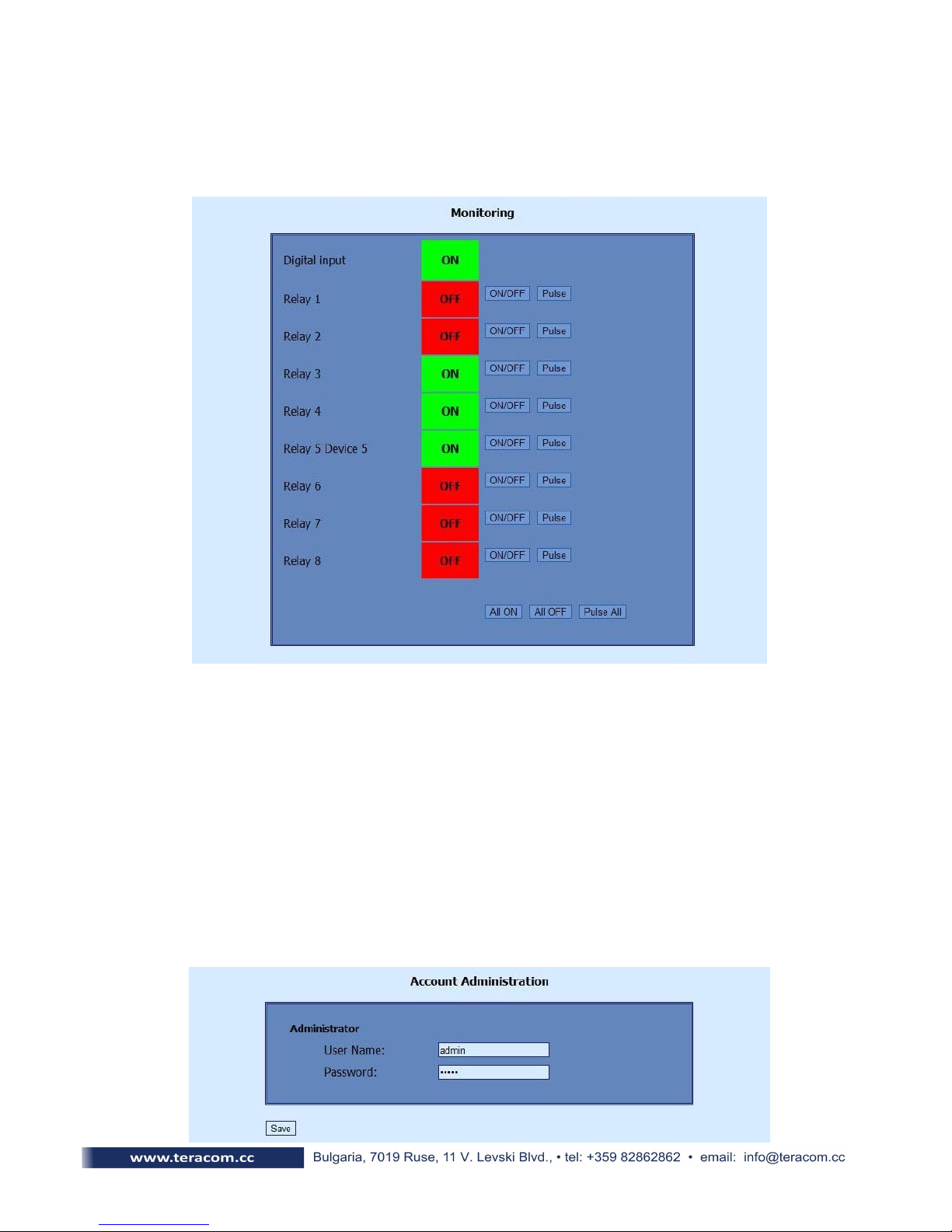
8.2 Monitoring page
After successful authorization, the onitoring page appears:
The onitoring page provides information about the state of the digital input and relay
output of the controller. To change the state of the relays , the “ON/OFF” buttons should be
pressed. If the Pulse button is pressed the relay will change its state for the time specified in the
“Pulse Duration” field in the “I/O Setup ” page. Three buttons are located on the bottom of the
page:
-All ON – clicking this button will turn all relays ON
-All OFF – clicking this button will turn all relays OFF
-Pulse All – clicking this button will change the states of all relay outputs fir the time
specified in the “Pulse Duration” field in the “I/O Setup ” page.
8.3 Account page
This page allows to change the user name and password for the web interface. After
entering the desired information, click the “Save” button.
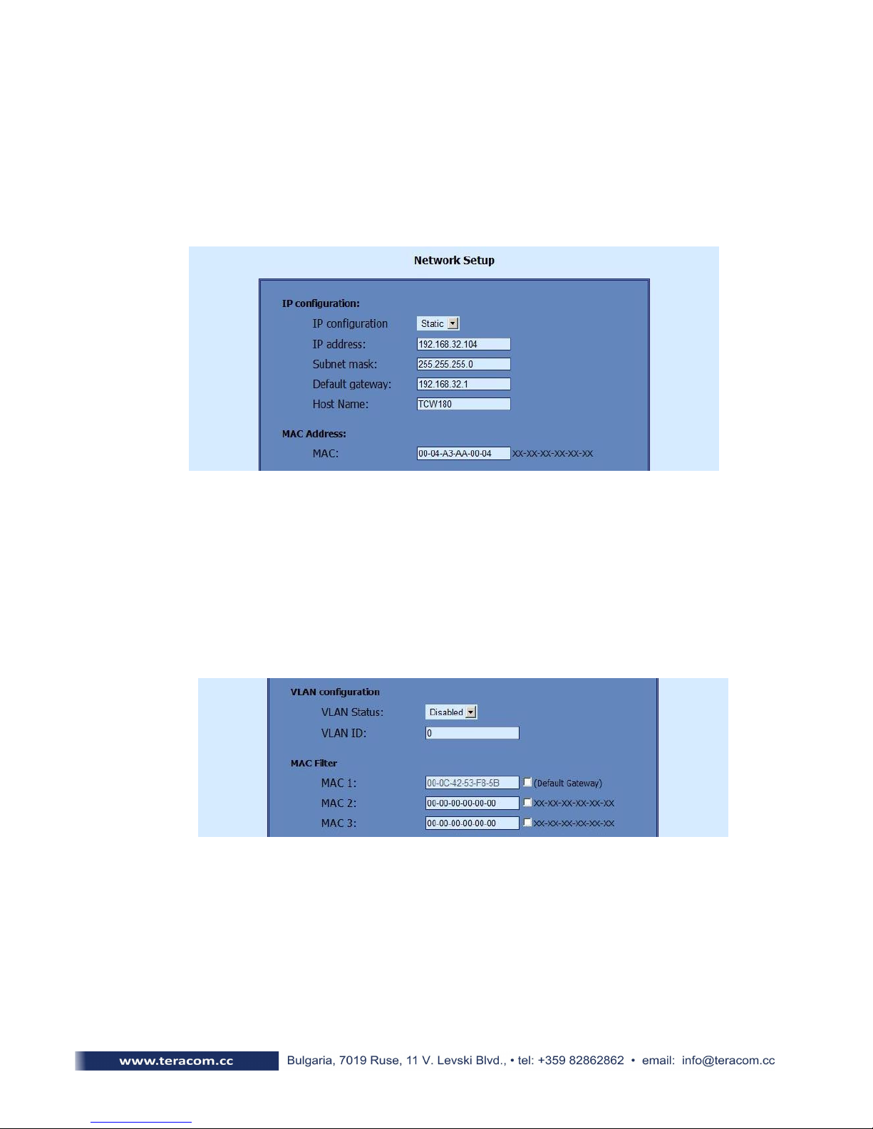
8.4 Network Setup page
The Network parameters are set on this page. The following parameters can be changed:
•IP configuration – IP Address configuration can be static or dynamic (DHCP)
•IP address, Subnet mask , Default gateway – these fields are active if IP address is
static
•Host Name
•MAC – device AC address
If multiply TCW180 controllers are used on the same network, please change the IP address
after connecting the device to the network. This will avoid devices installed on the network with
the same factory default IP address at the same time. It may be necessary to clear the arp cache
each time you connect new device to the network. This is done by typing arp -d in the command
prompt of a Windows computer.
In order to reduce network traffic and to limit the access, the controller supports VLAN and
AC address filtering. In addition to the AC address of the Default Gateway, another 2 AC
addresses can be added to the filter. The filter is enabled by marking the appropriate check box
after the AC address.
To set up the S TP server the following fields should be completed:
•Mailserver [IP:port] – IP address and port number of S TP mail server
•E-mail – sender mail
•Username&Password – these fields are required if using S TP server with authentication

8.5 SNMP Setup page
TCW180 supports SN P v.1 that enables the device to be part of large monitoring and
control networks. The possible settings are:
•SNMP Configuration – enable SN P v.1
•Read-Write community – performs client authentication
•Read-Only community – performs client authentication
SN P trap messages are sent for the following conditions:
-if event occurs on Digital Input (the signal changes its state)
-device restart
The following parameters can be changed:
•SNMP Traps – enable SN P trap messages
•IP address – IP address of the receiving host
•Community string – performs client authentication
•Trap Interval - time interval for SN P trap messages
•Max. number of Traps – maximum number of SN P trap messages sent, if trap
condition is present
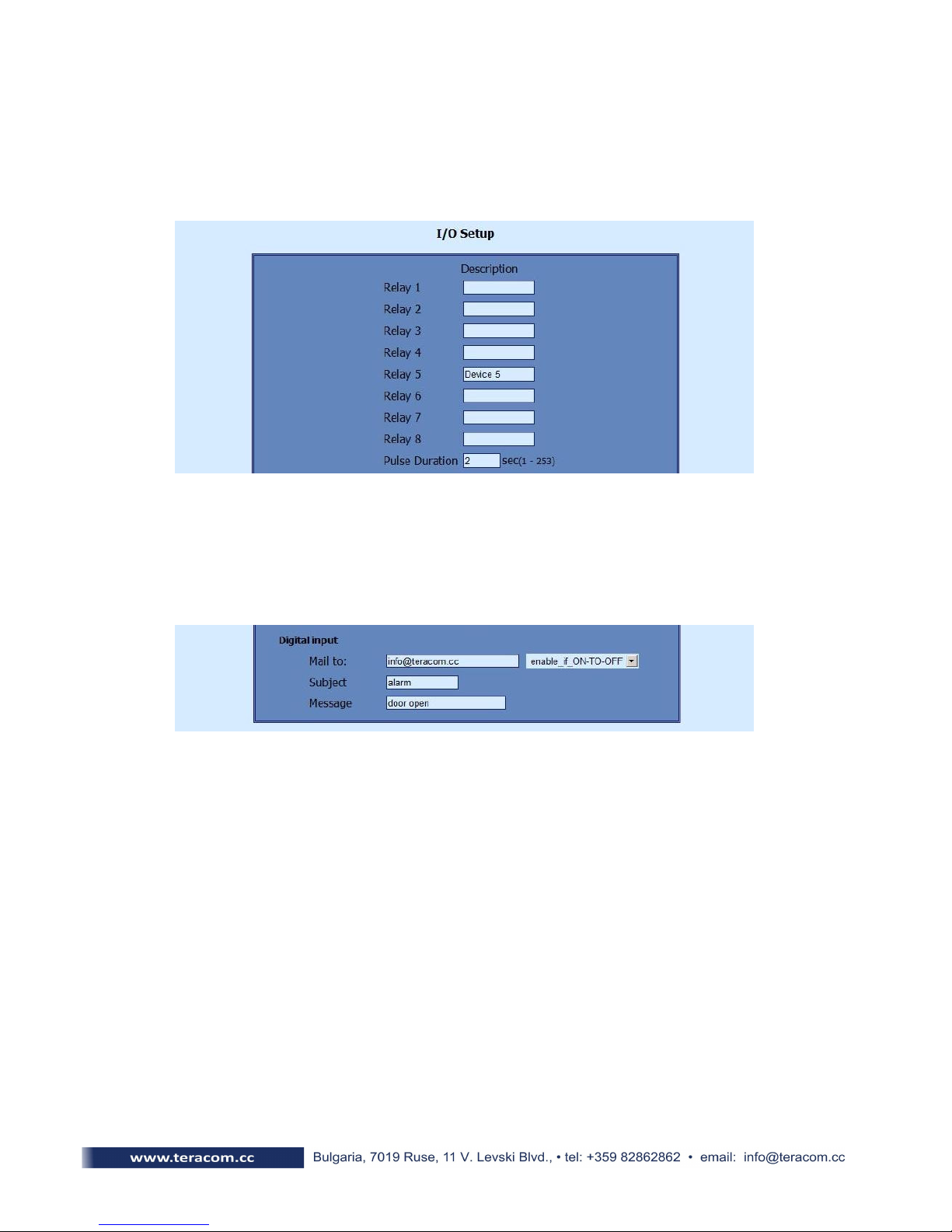
8.6 I/O Setup page
The following parameters can be set for the relays:
•Description – brief description of the output, maximum 10 characters should be used.
•Pulse Duration – time for which the relay changes its state, by pushing the "Pulse" button
on " onitoring" page. This setting applies to all 8 relays
TCW180 can be set to send e-mail alerts if an event occurs on the digital input. The following
fields should be filled:
•Mail to – recipient e-mail address
•Subject – e-mail subject
•Message – e-mail body
In the example above, if an event occurs (closing contact) the controller will send e-mail
message to info@teracom.cc with subject "alarm" and e-mail body "door open".

9. SNMP setup
TCW180 can be configured and monitored through SN P (Simple Network
anagement Protocol). This could be done using every SN P v.1 compatible program.
Parameters that can be changed, are grouped according to their functions in the tables below.
To obtain a valid OID number it is necessary to replace the “x” symbol with the prefix
”.1.3.6.1.4.1.17095”. To save the changes you should set a value ”1” of the
configurationSaved (OID x.8.0).
9.1 Product
OID Name Access Description Syntax
x.1.1.0 name read-only Device name String
x.1.2.0 version read-only Software version String
x.1.3.0 date read-only Release date String
9.2 SNMPSetup
OID Name Access Description Syntax
x.2.1.0 trapEnabled re ad-write TRAP me ssages enable /disable INTEGER { Ye s(1), No(0) }
x.2.2.0 trapRe ceive rIPAddress re ad-write TRAP me ssages re ceiver address IpAddress
x.2.3.0 trapCommunity re ad-write TRAP community String (SIZE ( 0..13))
x.2.4.0 trapInterval re ad-write TRAP me ssages interval INTEGER (0..255)
x.2.5.0 maxNumberOfTraps re ad-write aximum number SN P messages INTEGER (0..255)
9.3 Monitor and control
OID Name Access Description Syntax
x.3.1 digitalInput read-only Digital input state INTEGER { High(1), Low(0) }
x.3.2 Relay1 re ad-write Relay 1 state INTEGER { ON(1), OFF(0) }
x.3.3 Relay2 re ad-w rite Relay 2 state INTEGER { ON(1), OFF(0) }
x.3.4 Relay3 re ad-w rite Relay 3 state INTEGER { ON(1), OFF(0) }
x.3.5 Relay4 re ad-write Relay 4 state INTEGER { ON(1), OFF(0) }
x.3.6 Relay5 re ad-w rite Relay 5 state INTEGER { ON(1), OFF(0) }
x.3.7 Relay6 re ad-write Relay 6 state INTEGER { ON(1), OFF(0) }
x.3.8 Relay7 re ad-w rite Relay 7 state INTEGER { ON(1), OFF(0) }
x.3.9 Relay8 re ad-write Relay 8 state INTEGER { ON(1), OFF(0) }
x.3.10 Pulse1 re ad-write Relay 1 pulse state SYNTAX IN TEGER (0..255)
x.3.11 Pulse2 re ad-write Relay 2 pulse state SYNTAX INTEGER (0..255)
x.3.12 Pulse3 re ad-write Relay 3 pulse state SYNTAX IN TEGER (0..255)
x.3.13 Pulse4 re ad-write Relay 4 pulse state SYNTAX IN TEGER (0..255)
x.3.14 Pulse5 re ad-write Relay 5 pulse state SYNTAX INTEGER (0..255)
x.3.15 Pulse6 re ad-write Relay 6 pulse state SYNTAX INTEGER (0..255)
x.3.16 Pulse7 re ad-write Relay 7 pulse state SYNTAX INTEGER (0..255)
x.3.17 Pulse8 re ad-write Relay 8 pulse state SYNTAX INTEGER (0..255)
x.3.18 allOn re ad-w rite Set all relays On SYNTAX IN TEGER (0..255)
x.3.19 allOff read-write Set all re lays Off SYNTAX IN TEGER (0..255)
x.3.20 allPulse re ad-write Pulse all relays SYNTAX IN TEGER (0..255)

9.4 network
OID Name Access Description Syntax
x.4.1.0 device IPAddress re ad-write Device IP addre ss IpAddress
x.4.2.0 subnet ask re ad-write Subnet ask IpAddre ss
x.4.3.0 gate way re ad-write Gateway IpAddress
x.4.4.0 device ACAddress re ad-w rite Device A C Address OCTET STRING (SIZE(6))
x.4.5.0 dhcpConfig re ad-write DHCP ON/OFF INTEGER { ON(1), OFF(0) }
x.4.6.1.1.0 filte r ACAddress1 read-only A C Filter 1 (Gateway) OCTET STRING (SIZE(6))
x.4.6.1.2.0 filte r ACEnable1 re ad-write AC Filter 1 ON/OFF INTEGER { ENABLED(1), DISABLED(0) }
x.4.6.2.1.0 filte r ACAddress2 re ad-write AC Filter 2 OCTET STRING (SIZE(6))
x.4.6.2.2.0 filte r ACEnable2 re ad-write AC Filter 2 ON/OFF INTEGER { ENABLED(1), DISABLED(0) }
x.4.6.3.1.0 filte r ACAddress3 re ad-write AC Filter 3 OCTET STRING (SIZE(6))
x.4.6.3.2.0 filte r ACEnable3 re ad-write AC Filter 3 ON/OFF INTEGER { ENABLED(1), DISABLED(0) }
x.4.7.1.0 VLANStatus re ad-write VLAN status INTEGER { ENABLED(1), DISABLED(0) }
x.4.7.2.0 VlanId re ad-w rite V LAN ID INTEGER (0..4095)
x.4.8.1.0 smtpServer re ad-write S TP Se rver IP address IpAddress
x.4.8.2.0 smtpPort re ad-write S TP Se rver Port INTEGER (0..65535)
x.4.8.3.0 smtpSenderEmail re ad-write S TP Se nder e-mail address String (SIZE (0..39))
9.5 I/O Setup
OID Name Access Description Syntax
x.5.1.0 relayPulseDuration re ad-write Global Pulse duration INTEGER (0..255)
x.5.2.0 Relay1description read-write Relay 1 description String (SIZE (0..10))
x.5.3.0 Relay2description read-write Relay 2 description String (SIZE (0..10))
x.5.4.0 Relay3description read-write Relay 3 description String (SIZE (0..10))
x.5.5.0 Relay4description read-write Relay 4 description String (SIZE (0..10))
x.5.6.0 Relay5description read-write Relay 5 description String (SIZE (0..10))
x.5.7.0 Relay6description read-write Relay 6 description String (SIZE (0..10))
x.5.8.0 Relay7description read-write Relay 7 description String (SIZE (0..10))
x.5.9.0 Relay8description read-write Relay 8 description String (SIZE (0..10))
x.5.10.0 digitalInputAction re ad-write Digital Input Action condition INTEGER { FALLING(2),RISING(1),
DISABLED(0) }
x.5.11.0 digitalInputTo re ad-write Digital Input eve nt rece iver's e -mail
addre ss String (SIZE (0..38))
x.5.12.0 digitalInputSubject re ad-write Digital Input event e -mail's subje ct String (SIZE (0..11))
x.5.13.0 digitalInputBody read-write Digital Input event e -mail's body String (SIZE ( 0..22))
x.6.0 configurationSaved re ad-write Configuration save status
SAV ED/UNSAVED INTEGER { SAVED(1), UNSAVED(0) }
x.7.0 restartDevice re ad-write Restart Device INTEGER { RESTART(1), CANCEL( 0) }
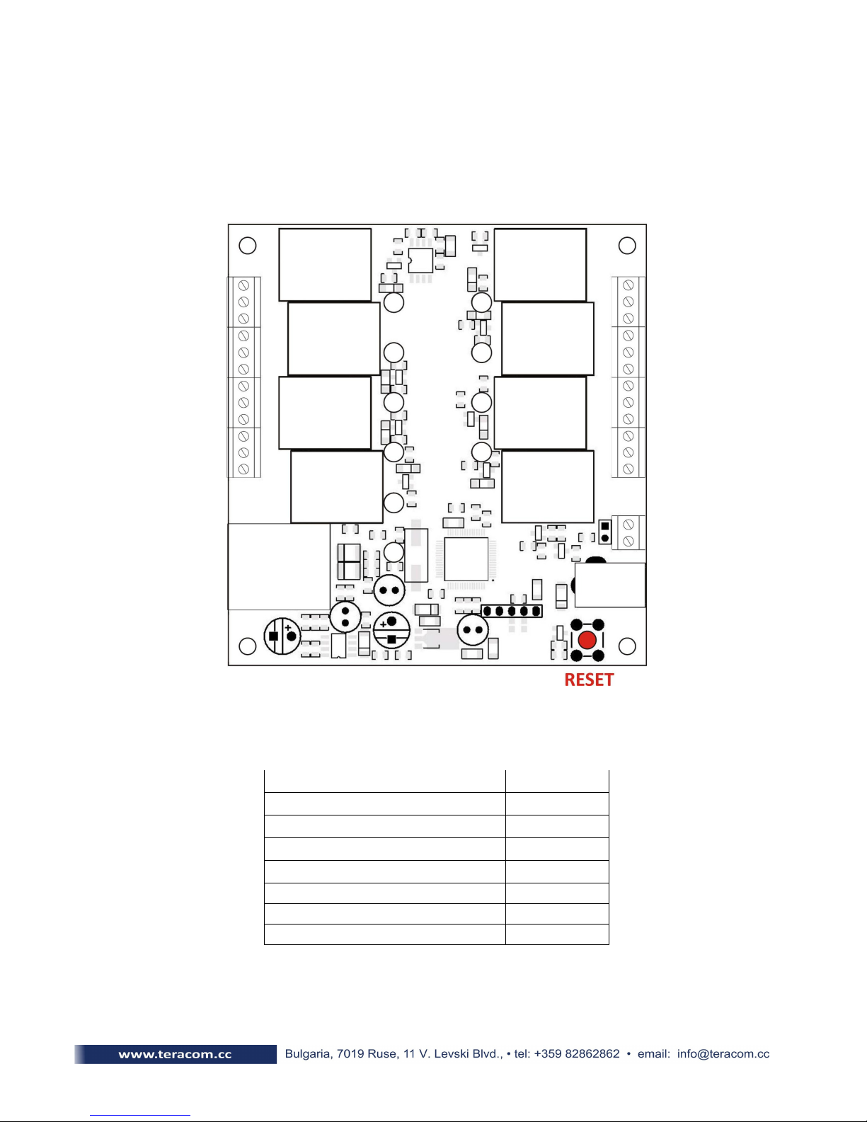
10.Restoring Factory Default Settings
If the IP address or password are forgotten, TCW180 can be restored to its original
factory default settings. To do this, please follow the steps below:
- remove the power supply from the unit
- press and hold the RESET button then turn on the power supply
- wait about 5 seconds and release the RESET button. The factory default settings are
shown in the table below:
User Name (Admin) admin
Password (Admin) admin
IP Address 192.168.1.2
Subnet ask 255.255.255.0
Default Gateway 192.168.1.1
SN PConfiguration disabled
readCommunity public
writeCommunity private

11.Firmware update
TCW180 supports remote firmware update. To do this please follow the steps below:
-Download the latest firmware version from www.teracom.cc . The extension of
the update file is .cod .
-Open Command Prompt window. In the example below in blue are the
commands that must be entered, and in red are the descriptions of these
commands :
C:\> -- go to the directory where the update file is located ( .cod extension)
C:\>ftp 212.73.154.53 -- FTP connection to the controller is made
Connected to 212.73.154.53.
220 Ready
User (212.73.154.53:(none)): admin -- enter username
331 Password required
Password: ***** -- enter password
230 Logged in
ftp> put tcw180v1.00.cod -- the update file is sent for update
200 Ok
150 Transferring data...
150 DON’T UNPLUG POWER CABLE FOR NEXT 2 INUTES!!! – 2 minutes after this message
appears, the de ice will be successfully updated
ftp: 157822 bytes sent in 60.89Seconds 2.59Kbytes/sec
ftp>
Re . 1 – May, 2011
DO NOT TURN OFF THE POWER SUPP Y DURING THESE 2 MINUTES!
TURNING OFF THE POWER SUPP Y WI DAMAGE THE DEVICE!
Table of contents
Popular Network Card manuals by other brands


König Electronic
König Electronic CMP-WNPCI41 manual

Eicon Technology
Eicon Technology Adapters user guide

HP
HP Rp7410 - Server - 0 MB RAM Performance guide

Sun Microsystems
Sun Microsystems StorageTek SG-XPCIE1FC-EM8-Z installation guide

Paradyne
Paradyne Hotwire 8323 installation instructions

ADTRAN
ADTRAN NetVanta 8044M quick start guide