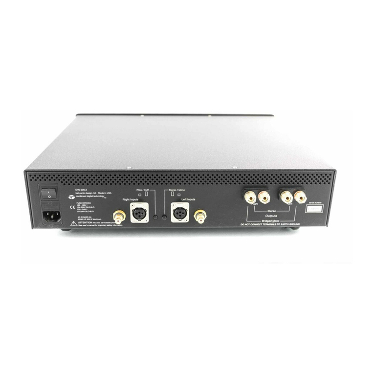
Terahertz Technologies PDA-750 User manual

PDA-750
Photodiode Amplifier
Operating Instructions
TerahertzTechnologiesInc.
169 Clear Road Oriskany NY 13424
TEL: (315) 736-3642 FAX: (315) 736-4078
www.terahertztechnologies.com
Copyright 2003-2006

Table of Contents
Topic Page
GENERAL INFORMATION
Introduction.............................................................................................................................. 1
Unpacking and Inspection........................................................................................................ 1
Power Requirements................................................................................................................ 2
Specifications........................................................................................................................... 2
OPERATING INSTRUCTIONS
Operation................................................................................................................................ 3
Display and Controls............................................................................................................... 4
Operating Considerations.........................................................................................................6
Rs-232 Operation ................................................................................................................... 7
WARRANTY INFORMATION
Repair Information.................................................................................................................. 8
Limited Warranty.................................................................................................................... 8

Introduction
The PDA-750 is a low noise, high gain transimpedance amplifier that is designed to provide a direct
digital readout of the current generated from a photodiode, photomultiplier, or other similar current
source. With full scale input ranges of 20 nAto 20 mAand a noise level of less than 1 pA, the PDA-
750 offers superb dynamic range.
Digital selection of a calibration factor in terms of Amps/Watt via the front panel controls permits
the unit to display the measurement directly in terms of Watts. The A/W setting may range from
1.000 to 0.100 in .005 steps. Subsequent current readings are divided by this cal factor when the
Amps / Watt control is engaged.
A variable bias voltage ranging from +14 V to -14 V may be digitally selected from the front panel
and applied in series with the photodiode under test. The background cancellation feature allows
offsets of from +100 % to -100 % of the selected full scale range to be added or subtracted from the
input signal.
Rechargeable batteries isolate the unit from the mains and eliminate the effects of ground loops
and/or power line noise. They will provide power to the unit for a minimum of 10 hours of opera-
tion between charges. The unit may be operated normally while the batteries are charging.
The large 4 1/2 digit Liquid Crystal Display provides a maximum resolution of 1 part in 20 000 thus
permitting the detection of very small changes in the variable that is to be measured.
An analog output is provided with a 2 volt full-scale signal that is proportional to the maximum
display reading of 20 000 counts. Applications for this unit include; serving as a readout for
Unity Quantum Efficient Detectors such as those manufactured by UDT Instruments, character-
ization of detector dark current, spectral calibration of detectors, and use as a sensitive, low cost
optical power meter.
The instrument may be controlled and interrogated by means of its built-in bi-directional Rs-232
serial port.
All settings are retained in non-volatile memory so that the user need not reset all values when the
unit is turned back on.
Unpacking and Inspection
Prior to shipment this instrument was inspected and found to be free of mechanical and electrical
defects. Upon acceptance by the carrier he assumes responsibility for its safe arrival. After unpack-
ing, examine the unit for any evidence of shipping damage. Should you receive this instrument in a
damaged condition, apparent or concealed, it must be noted on the freight bill or express receipt and
signed by the carrier’s agent. Failure to do so could result in the carrier refusing to honor the claim.
Upon filing a claim TTI should be notified.
-1-

Power Requirements
The PDA-750 is powered by a set of four AA size Nickel-Metal-Hydride rechargeable cells. It
may also be operated by its wall mount charging supply when access to line power exists. The
unit may also be powered from alkaline AA cells in cases where the batteries have run down and
no line power is available.
The batteries supplied will provide thousands of hours of operation. Failure to hold a charge for any
significant amount of time is evidence of the need to replace the cells. The batteries may be ac-
cessed by removing the two screws holding the back bezel in place. Slide off the top aluminum
cover. Observe and note the battery polarity markings whenever cells are being replaced. Replace
cover and bezels when the operation is completed.
PDA-750 Specifications
-2-
Full Scale Ranges..........................................................
MaxInput WithoutDamage............................................
Accuracy........................................................................
Amps/ Watt Setting.......................................................
Input Impedance...........................................................
Input Capacitance.........................................................
Output Impedance.........................................................
BiasVoltage..................................................................
Drift...............................................................................
V
oltageNoise................................................................
Noise.............................................................................
Background Cancellation...............................................
TemperatureCoefficient................................................
FrequencyResponse (-3dB)..........................................
Display..........................................................................
MaximumResolution......................................................
Power Requirements.....................................................
External Supply..............................................................
Dimensions....................................................................
Weight...........................................................................
Operating Temperature.................................................
Limited Warranty...........................................................
+/- 20n
A
to20 m
A
inDecade Steps
+/- 25mA
+/- 0.1%Rdg. +/- 2 L.S.D.
0.100 to1.000 instepsof .005
0 Ohms, Single Ended
25 pF
100 Ohms
-14 V to+14 V
< 5 pA/hr.after 10 minute warmup
< 1.8 μV P-P, 0.1 to10 Hz
< 1 pAp-p,DC-1KHzwith < 10pFDet.
+/- 100 %of range inuse
< 1 pA/ C
20 nA- DC to2.0 kHz, 100nA- DC to5.25
kHz,2μA- DC to22 kHz, 20μA,
200 μA, 2 mA, 20mA- DC to40 kHz
4 1/2 Digit, 0.4" HighLCD, 6rdgs/ second
1 part in+/- 20 000
RechargeableNMH Batteriesprovide
approximately 10 hours of use.
85 to260VAC,47-60 Hz, 15Wmax.
5.75"W, 9"L, 2.5" H
14.5 cm, 23 cm, 6.5 cm
2.5 Lbs., 1.13 kg Excluding Ext. Supply
0 - 40 C
2 Yearsfromdate of receipt
DO NOT attempt to use the charger with batteries other than Nickel-Metal-Hy-
dride cells as severe damage may be caused to the unit.

Operation
The PDA-750 is equipped with an electrically isolated BNC input connector. Current injected into
the center contact (with respect to the outer contact) provides a positive indication on the display.
The equivalent electrical circuit of the unit as is illustrated below.
1.2345
Input Output
Bias
Range
Equivalent Circuit
Displa
y
Current input to the unit generates a voltage across the range feedback resistor. This voltage is then
measured and displayed in units of amperes. A variable bias voltage may be introduced in series
with the detector in use. The output presented is calibrated such that 2.0000V represents the full
scale range in use, e.g. 2.0000 V corresponds to 20.000 nA and so on.
-3-
Control Function
Power
Offset
RangeSet
Amps/Watt Set
Bias Set
BiasEngage
Amps/Watt Engage
Set
Alternately applies and removes power to the unit.
Offsets the reading by up to +/- 20 000 counts.
Selects one of seven ranges in conjunction with rotary Set control. Units
LEDs and decimal points indicate the range that is currently in use.
Momentary push button used in conjunction.with rotary Set control.
Inputs an A/W cal factor that is displayed while button is pushed.
Momentary push button used in conjunction.with rotary Set control.
Selects a level of bias voltage that is displayed while the button is
pushed. Pushing in on rotary control accelerates the setting.
Alternately enables/disables the A/W setting. When engaged, all subse-
quent current readings are divided by the A/W cal factor. LEDs will then
indicate units of Watts.
Alternately adds or removes the selected bias voltage in series with the
input.
Changes the value of the variable selected by the Set button in use.
For the remainder of this discussion refer to the front panel display and controls drawing that appears on the
following page.

-4-
PDA-750 Front Panel Controls

Operation
The operation for measuring photodiode current is as follows:
1. Disengage both the Bias and Amps/Watt Engage push buttons.
2. Select the range that includes the highest expected current to be measured. If this is unknown,
select the least sensitive range.
3. Before connecting the photodiode, adjust the Offset Control for a zero reading on the dis-
play.
4. Connect the photodiode to the instrument by means of the Input BNC connector.
5. Illuminate the photodiode with the light to be measured. The display will then indicate the mag-
nitude of the input current.
6. If a reading in units of Watts is desired, input the current responsivity of the detector by
depressing the A/W Set push button and adjusting the SET control knob until the desired value
is displayed. Depressing the A/W Set button will divide all subsequent readings by the
responsivity value and the units LEDs will switch to the appropriate value of Watts.
7. If reverse bias is desired, depress the Bias Set button. The bias voltage will then be dis-
played. Adjust the Rotary Set Control for the desired magnitude and polarity. Depressing the
Bias Engage button will then apply this voltage in series with the photodiode. NOTE: it is not
advisable to forward bias most photodiodes. Make sure that the bias is of the proper
polarity such that the detector is reverse biased.
8. If the display is blanked, the unit is indicating an over-range condition. Change the range to
progressively less sensitive ranges until the display indicates an on-scale reading.
9. If the BAT LO annunciator is activated on the LCD display, the batteries require charging. This
may be accomplished by plugging in the wall-mount power supply provided with the unit. The
instrument may be operated while the batteries are charging. Recharging requires about 14 hours
from a fully discharged condition. The microproccessor will automatically shuthe unit down if the
batteries are too low to be used.
10. If it is necessary to measure a small signal in the presence of ambient light, the OFFSET
Control may be used to null the background light to zero with the signal of interest turned off.
This subtracts the background illumination from the signal of interest. Note that detector noise
will increase with a large background signal.
11. High detector capacitance and/or cable capacitance will add add to the noise level.
-5-

Operating Considerations
Input Offset Voltage Effects
Theinput offset voltageof the PDA-750 in conjunction with the shuntresistance of thephotodiode in
use will cause an offset current to be generated. For example, let us consider the case of a germanium
photodiode that is intended to be used at zero bias voltage. Typical shunt resistances of small germa-
nium detectors are in the range of 100 K. The maximum input offset voltage of the PDA-750 is 100
μV. The input offset current will then be: 100 μV/100 K = 1.0 nA. This current may be nulled out
with the offset control. Note however that shunt resistance is reduced by approximately half with
every 10 C increase in detector temperature. Dark current levels should be checked frequently when
makingvery sensitive measurements.
InGaAs detectors provide higher shunt resistances than germanium and offer similar spectral sensi-
tivity. Silicon detectors provide higher resistivity yet but their responsivity falls off rapidly for
wavelengths longer than 1000 nm.
Noise Considerations
Noise in a transimpedance amplifier is governed by three primary effects. The first is Thermal or
Johnson Noise. The output voltage noise generated is given by:
Where k is Boltzmann’s Constant, T is the temperature of the feedback resistor in degrees Kelvin,
Rf is the value of the feedback resistor in Ohms, and BW is the bandwidth of interest.
The second noise source is shot noise. This is due to the quantum nature of electrons. It is given by:
Where: e represents the charge of the electron in Coulombs and I is the input current.
The voltage noise of the amplifier provides the third important source of noise. The noise current is
represented by the voltage noise divided by the impedance represented by the source impedance in
parallel with the feedback impedance.
-6-
Vnj = [ 4k T RfBW] 1/2
Vns = Rf[ 2e I BW]1/2
Vnv (ω) = Rfen(ω) / [Rf / jωCinRf+1]
Where ωrepresents the angular frequency of interest, en(ω) represents the voltage noise of the
amplifier, and Cin represents the capacitance of the source. The input resistance is assumed to be
high compared with the feedback resistance. Integrating this expression over the bandwidth of
interest provides the noise contribution.

As the values of input voltage noise, feedback resistance, and bias current are fixed, the main vari-
ables under control of the user are the input capacitance, and shunt resistance of the source. The
lowest noise levels and DC errors will be provided by detectors with low capacitance and high shunt
resistance.
Large detector capacitance will cause gain peaking and thus ringing of the output waveform follow-
ing step functions of the input. The junction capacitance of a semiconductor detector may be re-
duced by reverse biasing of the detector in order to increase the depth of its depletion region. This
will however, increase the DC errors observed since the bias voltage generates an error current
(known as detector dark current) when impressed across the detector shunt resistance.
Rs-232 Operation
The PDA-750 is equipped with a bi-directional “three-wire” Rs-232c interface. It permits the unit
to be remotely controlled via an external computer and will report readings and the unit’s status
on request.
An interface cable is supplied with each unit. Plug the RJ-14 (telephone style) connector into the
port on the unit’s rear panel. Plug the 9 pin D connector into the computer serial port. Using a
communications program (such as WINDOWS Hyperterminal) set the appropriate communica-
tions parameters. The protocol is 9600 N 8 1, i.e. Baud Rate of 9600 Baud, no parity bit, 8 data
bits, and one stop bit. The command structure is as follows:
-7-
Prefix Command Carriage
Return
P: READLAST CR
Command List Function
P:READLAST INVOKES THE SENDING OF THE CURRENT READING
P:STATUSRQ INVOKESTHE SENDING OFTHE UNIT’S STATUS
P:USERNG0X SETS RANGE (X = 0-6) (0 is the most sensitive range)
P:BS-14.00 SETS BIAS FROM -14.00 V TO +14.00 V
P:A/W1.000 SETSA/W VALUE TO 0.100 TO 1.000
P:SETBIASX TURNS BIAS ON (X = 1) OR OFF (X = 0)
P:TURNA/WX TURNS A/W ON (X = 1) OR OFF (X = 0)
CR is Carriage Return, hex 0D, or Enter on a PC keyboard. The significance of the characters is as
shown above.A correct command will be met with the response: “OK”.
An incorrect command will be met with the response: “Invalid Command”.
Note: The PDA-750 is configured to automatically transmit readings following each measurement
without the need for a command. This occurs at a rate of approximately six readings per second. To
turn off streaming, send an XOFFcharacter. To resume streaming, send an XON control character.

Warranty And Repair Information
REPAIR INFORMATION
Products manufactured by Terahertz Technologies Inc. are designed and fabricated to provide reli-
able performance. However, in the event that service is required, both telephone technical assis-
tance and factory repair services are available. Call (315) 736-3642 for information. For IN-WAR-
RANTY REPAIRS, call us to obtain a Returned Material Authorization number, (RMA Number).
All products are to be returned to TTI with freight charges pre-paid. Those products sent under
warranty will be returned to our customers pre-paid. We cannot be responsible for returned prod-
ucts that do not reference the TTI RMA number. For OUT-OF-WARRANTY repairs, services are
billable for both time and materials.
LIMITED WARRANTY
TERAHERTZ TECHNOLOGIES INC. (TTI)WARRANTS THAT TOTHE FIRST PURCHASER,
FOR A PERIOD OF TWO YEARS FROM THE DATE OF RECEIPT, THAT THIS PRODUCT
(THE PRODUCT) WILL BE FREE FROM DEFECTS IN MATERIALS AND MANUFACTUR-
ING. THE FOREGOING WARRANTY IS THE ONLY WARRANTY, EXPRESS OR IMPLIED,
GIVEN BY TTI, I.E., THERE IS NO WARRANTY OF FITNESS FOR A PARTICULAR PUR-
POSE. TTI HEREBYDISCLAIMSANYEXPRESS OR IMPLIED WARRANTYOTHER THAN
THE WARRANTYIN THE FIRST SENTENCE TO THE FULLEST EXTENT PERMITTED BY
LAW. THE SOLE AND EXCLUSIVE REMEDY UNDER THIS WARRANTY IS REPAIR OR
REPLACEMENT AT TTI’S OPTION OF ANY PRODUCT THAT PROVES TO BE DEFEC-
TIVE IN MATERIALS OR MANUFACTURING WITHIN TWOYEARS OF RECEIPT OF THE
PRODUCT. NOTE: THIS WARRANTY DOES NOTAPPLYTOANY PRODUCTWHICH HAS
BEEN SUBJECT TO MISHANDLING, MISUSE, OR SERVICE BY UNAUTHORIZED PER-
SONNEL OR TO ANY PRODUCT WHICH HAS BEEN DAMAGED, MODIFIED, ALTERED
OR TAMPERED WITH. TO THE FULLEST EXTENT OF THE LAW, TTI DISCLAIMS ALL
LIABILITY FOR ANY OTHER DIRECT, INCIDENTAL OR CONSEQUENTIAL DAMAGES
ALLEGED TO BE CAUSED BYADEFECTIVE PRODUCT, I.E., TTIWILL NOTBE RESPON-
SIBLE FORANYPERSONALINJURY, PROPERTYDAMAGE OTHER THAN THE COSTOF
REPLACING THE PRODUCT OR ANY OTHER MONETARY DAMAGE SUCH AS LOST
WAGES OR PROFITS CAUSED BY ANY USE, ATTEMPTED USE OR INABILITY TO USE
THE PRODUCT. NOTE: BY USING THE PRODUCT, YOU AGREE THAT REPAIR OR RE-
PLACEMENTAT TTI’S OPTION WILL FULLY SATISFY TTI’S WARRANTY OBLIGATION
TOYOU,WHETHER INCONTRACT,TORT,NEGLIGENCE, STRICTLIABILITYOR OTHER
APPLICABLE LAW.
-8-
Table of contents
