Terak 8510/a User manual

).
"
-:"
'System Installation
~§[][QJ/§]
GRAPHieS
COMPUTER
SYSTEM
8510/a
GRAPHies
COMPUTER
SYSTEM
INSTALLATION
&
USERS
GUIDE
This document describes the installation of aTERAK 8510/a Graphies Computer
System. Single and multiple disk drive configurations are presented, along with
system acceptance test procedures. Operating environment requirements, abasic
troubleshooting guide, maintenance
procedures
and descriptions of the system
components
are also included. Contained
in
appendices are descriptions of the
system modules and apart number listing of the major assemblies.
teral<
SCOrr5DALE,
ARIZONA
Part
No. 50-0010-001
"TERAK
CORPORATION
believes
that
the
infornlation contained herein
is
accurate.
In
no
event
will
TERAK
be
Hable
for
any losses
or
damages whether direct or indirect resulting from the
use
of
such
information, including, without limitation,
lasses
arising frorn claims
of
patent,
copyright,
and
trademark
infringement. No license
is
granted
hereby
for·the
use
of any
patent
or
patent
rights of
TERAK.
TERAK
reserves
the right
to
update
the
information contail1ed herein at
any
time without
further notice.
The
inforrnation
contained
herein is proprietary
to
TERAK,
CORPORATION
and
must
be
treated
as
confidential.
It
may
not
be
disclosed
to
others
or
used
for
any
purpose
except
as
expressly
consented
ta
by
"·ERAK."
8510/a
GRAPHieS
COMPUTER
SYSTEM
INSTALLATIO,N &
USERS
GUIDE
Part
No. 50-0010-001
FIRST
EDITION
Copyright
1980
by
TERAK CORPORATION
"Ail Rights Reserved"
TERAK
is
atrademark
of
TERAKCORPORATION.
DEC,
PDP-l1,RT-ll
and'LSI-l1
are
trademarks
of
DIGITAL
EQUIPMENT
CORPORATION.
{

CONTENTS
PAGE
)
INTRODUCTION.
... . 1
SECPflON
1.
PRE-INSTALLA~rION
CONSiDERATIONS
t,
••••••••••••••••••••••••••
2
1.1
PHYSICAL
INSPEC1-ION
OF
SYSTEM
COMPONENTS
,)
2
1.2
SYSTEM
POWER &OPERi\TING ENVIRONMENT REQUIREMENTS 2
1.2.1 Input Voltage &Frequency Options 2
1.2.2
Power
Requirements
t
•••••••••••••••••••••••••••••••••••
2
1.2.3
Temperature
Limits 2
1.2.4 Relative Humidity R,ange 3
1.3
UNIT
DIMENSIONS
' 3
1.4
UNIT'WEIGHT
'3
2.
SYSTEM
INSTALLATION
PROCEDURES
3
2.1
SINGLE DISK
DRIVE
CONFIGURATI()N 3
2.2
MULTIPLE
DISK
DRIVE
CONFIGURAT·ION 4
58
UNIT
COVER
REMOVAL-REPLACEMENT
8
5.1 8510, 8512 &8515 UNITS 8
5.2 8532-1
MONITOR
9
6.
UNIT
AC
INPUT
VOLTAGE
SELECTION
9
6.1
8510/12/15 UNITS 9
6.2
8532-1
MONITOR
UNIT
11
7.
UNIT
CHANGES
FOR
50
Hz
&
60
Hz
AC
POWER
FREQUENCIES
12
8.
IJ~~I<:
1rIl(){jIJI-IE5;II()()lrl~(i
13
9.
SYSTEM
DESCRIPTION
a
•••••••
a
••••••••••••••••
a
•••••••••••••••••
17
9.1 8510
DATA
PROCESSOR
SYSTEM a
••••••••••••••••••••••••••••••••••••••••••
17
9.2·
8532-1
MONITOR
a'
•••••••••••••••••••••••••••••••••••••••••
a
•••••••••
a
••••
a
•••••
0
••••••
17
9.3 8532-2.KEYBOARD a
••••••
a
•••••••••••••••••••••••••••••••••••••••
a
••••••••••••••••••••••
17
9.4 8512 DISK SUBSYSTEM
17
9.5 8515 EXPANSION
SySTEM
a
•••••••••••••••••••••••••••••••
a
•••••••••••••••••••••••••••
19

(
f,
)
APPENDICES
PAGE
A.
Diskette Handling/Storage
Considerations.
. . .
.. ..
~
..
1 1
••••••••••••••
1
•••••
~
••••••••••
, • •
••
Al
thru
A2
B.
Suggested Maintenance 0 • 0
••••••••••••••
0
••••••
>
•••
0'
••••••••••
0 • 0
••
0 • 0
••••••
0 0 • 1
010
•••••
BI
C. Processor Reference Guide 0
•••
0.0
•••••••
1'
•••
1
••••••••••
1
•••
1
•••
1
••••••
0
•••••••••
0
......
Cl
thru
C44
D. Video Controller-Memory Reference Guide
...
0'
•••••••••••••
0
••••••
0
•••••••
0
••••
0 1 0
•••
0
'0
Dl
thru
08
E.
Diskette Controller Reference Guide
..
0
•••••••••••••
0 • o
••••••••••••
o
••
o0
El
thru
E19
F.
Asynchronous
SeriaI Interface Reference
Guide
1'
•••••••••••••••••••
0
••••••••
0 0
••••••
fl
thru
F5
G. Parallel Interface Reference Guide
~
Gl
thru G5
H.
Use
of
Control
Console Mode (Micro-OOT) 1
•••••
1
••••••••••••••••
1
•••••
~
•••••••
••
•
••
Hl
thru
1-I5
1.
TERAK
Part
Numbers, Major Assemblies 1
•••••••••••••••••••••••••••••••
0
,"'
••••
1,.1.
Il
LIST
OF
FIGURES
FIGURE
NO.
System Components '0 • 1
••
0
•••••
0 • 0
••••
0 0
••
1··1
Single Disk Drive Interconnections 0
••
0
•••
0 • 0
••••••
0 • 0 • 0
••
0
••••
0
•••
0 0 0
••
0
•••
0 0 0 • 0 • 0
••••
0
•••
0 • 0
2-1
Multiple Disk Drive Interconnections o
••
0
••••••
0 • 0
•••••••
0
•••••••••••••
000
••
0 • 0 • 0
••
0 0
•••••
0 • " 0
••••
0 0
2-2
8510/a Module Locations &
I/C)
Priority
0.0
•••••••••
0
••••••
0.
0 • 0
••
0
•••
0 0
••••
0 • 0
••••••••
0
••
0
••
'0'
0 •
••
4-1
Bus Extension Interconnections 0
•••••
0
••
0
•••
0 • 0 • 0
••••
0
•••
0
•••••••
0 0 • 0 • 0 • 0
••
0 • 0
•••••••
0 • 0 0
••
0 • • • • •
••
4-2
EIB
Locations
..
0
••••
0
•••••
0 0 • 0
•••••
0
•••••••••
0
•••••
0
••••
0 • 0 • 0 • 0 • 0
••
0
•••
0 0
••
0 0 0 0
••••
0 • 0
•••••••••
0
4-3
8510/12/15
Caver
Removal-Replacement &8510/15 Module Retaining Hardware 0
00
••••
0
•••
0
••
0 •
0.01.
• •
••
5-1
8532-1
Monitor Chassis Ren1oval-Repla.cement 0 0 • 0 0
•••••••
0 0
••••
0
••
0
••
0
••
0 0 • 0
•••••••••••
0 • • •
••
• 0 • •
••
5-2
8510/12/15 AC Input Voltage Selection .000
•••••••
0
•••••
0
•••••
'0
••
0 • 0 • 0
••
0.
0
.0'
••••
0 0
••
0
•••
'~
•
••••
•
••
6-1
8532-1
AC Input Voltage Selection
..
0
•••
0
•••••
0
••••••••••••••••
0 • 0
•••
0
••••••••
0 0 • 0
••••
0
••••••••
0
••
0
6-2
8510/a Troubleshooting Guide
000
•••
0
•••
0
••
0.0
•••••
000.0
•••••••••••
0
••••••
0 •
••
8-1
8532-2
Keyboard Unit Output Codes
00
••
0.00.0
••
0
•••••
0 0
•••
0
•••
0
••••••••
0
•••••••
0 0 •
00'
•••••
0
•••
0 •
••
9-1
8532-2
Keyboard
Layout .0 • 0 • 0
•••••
0 0 • 0 0 0
•••
0
••
0 • ,
•••
0
••••••••••••••••••
0
••••••
0 • 0
••
0 • 0 0 •
000
..
0 • • •
••
9-2
Diskette Loading
..
0000
•••
0 0 • 0 0 • 0
.0'
•••
0 • 0 0
•••••••••••••••••
0 • 0
•••
0
••
0
••••
0'
•••••••
00.
00
••••••••••
A-l
Diskette HandlingJStorage Considerations
...
0
••••
0 • 0
••
0
••••••••••
0
••
0
•••••••••••
0
••
0
••
0
••••
0 0 • • • • •
••
A-2
General I<egister Identification 0 0
•••
0 0 0 • 0 • 0
••
0 • 0 0 • 0
••
0 • 0 • 0 0
••••
0 0 • 0 0 0
•••
0000000• 000
••
0 0
•••
0
•••
0 • 0 •
o'
C-l
High and Law Byte .0 0 0 0
••
0
••
0
••
0 • 0 0 0 0 0
••
0 • 0 •
0"
••
0
••
0 • 0 0
••••
0 • 0 • 0 • 0 0 0 0 • 0 0
•••••••••••
0 •
'.
0
••••••••
0 0
C-2
Ward
&Byte Addresses
for
First
4K
Bank
o,.
0 • 0 • 0
•••
0
••
0 • 0
•••
0 0 • 0
••••
0 0 • 0
••••
0 • 0 • 0
•••
0 0 0 • 0 • 0
•••
0 •
••
C-3
Processor Status Ward (PS) o
••
0
••••••••
0 0 • 0 • 0 0
••••••
0
•••••••
0
••••
0 • 0 0 • 0 0
••
0 • 0 0
•••
0
••
0
••
0 • 0 0 • 0
•••
0 0 C-4
System Memory Organization .0 • 0
••••••
0 0
•••••••
0 • 0
•••••••••
0 0
•••••••••••••
0 0
•••••
0 • 0
••••
0 0
••
0 • •
••
D-1
Display Geometry
..
0
••
0 • 0
••••••••
0
•••••••••
0 0
••
0
••••••••••••
0
••••••••••••
0 0
••
0
•••••
0 • 0 0 • 0
••••••••
'D-2
Composite Video Waveform at 8510 Video
EIB
BNe
0
•••••••
0 •
o'
•0
••••••
0 • 0 • 0 0
•••••••••
00
D-3
Graphie Address Register (GAR) 0 0
•••
0
•••
0 • 0
••
0
•••••••
0
••••••
0
••
0
•••••
0 • 0
•••••
0
•••
0
••
0
••
0 0 0
•••
0
••
0 0
D-4
,Video Control Register (VeR)
..
0
•••
0 • 0 •
00'
••
0
••
0 0
•••••••••••
000
•••
0 0 • 0 • 0
••
0 • 0 • 0 0
00
••
0
•••
00'
00'
0 0
.0
D-5
Generator Buffer Address Format
o.,
0 0 0 0 0 0 0
••
0 0
••
0 • 0 • 0
•••
00'
0
•••
00
••
0
00'
••••••
0
.00.
0 • 0 • 0
0000
•••
0 •
o'
0-6
Page Buffer Address
Format.
0 0 • 0 • o
••
0 • 0 • 0 0 • 0 • 0 • 0 0 0 • 0 0 0
••
0
••
0
0000000
••
00'
0 0
0000
••
0 0 0
0000000
••••••
o'
D-7
Video Index Register
(VIR)
0 0
••••
0 • 0 0 0
••
0 0 0 0 • 0 0
••
0
••
0 0
•••
0
•••
0 0 0 0
••
0 • 0 0 0 0 0 • 0
••
0 0 • 0 • 0 0 0 0 0 0 0
••••
0
••
0 0
D-8
Keybaard Data Bufter
(KDB)
0 0 0
••
0 • 0 0 0 0 • 0 0
•••••••
0 0
••
0 0
••••••
0
••
0 0
••
0 0 • 0 • 0 0 0
••••
0 0 • 0
••
0 0
••
0
D-9
Keyboard Status Register
(KSR)
.0 0
••
0 0 • 0 0 0 • 0
••••••
0 0 0
••••
0
•••••••••••
0
•••
0000• 00000
••
0 0 0 0 0 0
••••
o'
0-10
Emulator Data Buffer
(EDB)
o'
0
••
0 0 • 0 0
••
0 0 0
••••••
0
•••••••
0
••
0 0 • 0 • 0 0
••••
0 0 • 0 0 0 • 0 • 0 0 0 0 • 0 0 0 0 0 • 0
D-11
Emulator Status Register
(ESR)
...
0 0 0
••
0 • 0 • 0 0
••
0 0
•••
0 0 0 0 • 0 0 • 0 0 • 0
••
0
••••
0 0 • 0 0 0
•••
0
••
0 0 • 0 • 0 0 0 0 0
••
0 • 0
0-12
Diskette Controller Control &Status Register (QXCS)
00'
o'
0 0
•••
0 • o
••••
0
••
0'
00'
••
00000
•••
000
•••••
o.
00'
E-l
Diskette Controller Data Buffer (QXCB)
..
0.0
•••
0 0
•••
0 • 0
•••••••••••••••••
0 • 0
••
0
••••
0
•••
0'
0 •
00
• 0
.0
••••
E-2
Diskette Controller
ROM
Listing 0 0 • 0 0 • 0 0 0
••
0 0 • 0 0
•••••••••••••
0 0
•••••••••
0 • 0 0 0
••
0 0
••••••
0 0 0
••••••••
0 •
E-3
Diskette Controller Sample System Bootstrap Listing o
••
0
•••
0 0
••••••
0 0
•••
0 0 0 0 • 0 • 0
••••
0
•••
0 0 0 0
...
0 0
••••••
E-4
Diskette Controller Listing of Dummy Boat Example
....
0
••
0
•••••••••••
0 0 0
•••••••
0 0 0 0
••
0 0 0
•••
0
••••
0 • 0 •
E-5
SeriaI Interface
EIB
Connector &Switch Functions o
•••••••
000
••
00'
••
00'
0.00000.
0
o'
••
0
••
0.0
••
0
••
o'
•••
F-1
Single Seriai Current Loop &J3 'Wiring
..
0 0
••
0 0
•••
0 0
000
••••
0 • 0 •
o'
00'
0000
••••
0
••
0
•••
0 0 • 0 0 • 0
.00000.00
••
F-2
Parallel Interface
EIB
Connector &Module
Jumper
Functions
.0.0
••
0 • 0
•••
0 • 0
•••
0 •
0000000.
0
••
o'
•0000000 G-1
Data &Control Word Formats 0 0 • 0 0 • 0
••••
0
•••
0 0
••••••••••••
0 • 0 0
•••••
0
••
0
•••
0 • 0 • 0
•••••
0
••
000
••
0 • 0 • 0
G-2
1/0 Data Transfers
.0
•••••••
0
•••••
0
••
0
••
0
000
••••
0 0 0 • 0
•••••
0
••
0 • o
••••
00
••
0
••••
0 0
••
0 • 0
•••
0
••
0 •
00
••
o'
G-3
8510/a HALT Switch Module
...
0 0
•••••
0 0
••••••••
0
••••
o'
•••••
0
•••••
0
0.0
••••
0
••••••••
0 0
••
00'
••
0 0
••••
H-1

:(
.
<,

INTIIODUCTION
)
The
TERAK
8510/a
is a
general-purpose,
disk-based
cornputer
intended
for
data
processing
and
medium-
resolution
.graphies applications. A320 x240
dot
pattern
and/or
1920
eharacters
(24 lines of 80)
can
be
displayed
(under
program
control)
on
a
12
in.
monochrome
CRT.
Four
drives,
accommodating
IBM 3740
formatted
(8 in.)
Happy
di?kettes,
can
be
included
in a
systern
configur-
ation.
The
hardware
is
madularized
into a
keyboard
unit,
a
CRT
display, a
data
proeessor
unit,
bus
expansion
unit
and
optional
drive units. T'he
system
companents
are
shawn
in Figure
1-1.
AlI
components
are
light-weight
and
are
suitable
for office
and
laboratory
environments.
This
document
describes
the
installation
of
aTERAK
8510/a
Graphie
Computer
System.
The
installation
consists
of
the
interconnection
and
aeceptance
testingof
the
system
hardware. Aiso included is abrief trouble-
shooting
guide
and
system description.
Appendices
contain
diskette
handling/storage
considerations,
sug-
gested
maintenance
procedures,
a
parts
list
and
reference
guides
for
the system hardware.
Figure
1·1
System
Components
0001-000
1
1PRE-INSP"f
ALLATION
CONSIDERA,TI'ONS
1.1
PHYSICAL INSPECTION
OF
SYSTEM
COMPONENTS
Carefully unpack
aU
the shippingcontainers; save
aH
the
containermaterials for equipment
storage
or
future re-
shiprnent.
Each
container
is
marked
with
the
'unitpart
number(s)
and individual seriaI number(s). (AppendixI lists
the
part
numbers
of the major assemblies.)
Use
the
fol1owing
1iSt5
ta
verify
the
contents
of
each
container.
8510
Container:
8510
Data
Processor
1ea.
8510/a
Systern
Acceptance
,Disk 1ea.
8510/a Docurnentation Kit 1ea.
AC
Power
Cord
. . . . . . . . . . . . . . . . . . . .
..
1ea.
8515 Container:
8515
Expansion
System
0
1ea.
Cable, Aux. Drive,
Short
1ea.
8510
Bus
Exte,nsion
EIB
(packed
inside
the
8515 unit) 1ea.
AC
Power
Cord
. . . . . . . . . . . . . . . . . . . .
..
1'ea.
8512
Container:
8512
Disk
Subsystem
1ea.
Cable,
Aux. Drive,
Short
~.
1ea.
A,C
Power
Cord
. . . . . . . . . . . . . . . . . . . .
..
1ea.
8532-1,
8532-2
Container:
8532-1 Monitor 1ea.
8532
Monitor
Cable (6 ft.)
..........•...
lea.
8532-2
Keyboard
(with integral 8532
KeyboardCableAssembly)
';
1ea.
AC
Power
Cord
'
..
'. . . . . . . . . . . . . . . . . .
..
lea.
Inspect
aIl
iteIns
for
obvious signs of damage.
DO
NOT
interconnect
a
damaged
item
ta
asystetn;
contact
T'ERAK,
or its representative, for further information.
NOTE:
The
8510, 8512
and
8515 diskdrive-heads
are
protected
during
shipmentby
foam
blacks
that
are
inserted
in
the
disk drive openings. These
blocks
ensure
that
the
cloors
will
stayopen,
so that the -drive ,heads
remain
unloaded
(not clown)
and
therefore
protected.
Remove
and
save
these
blocks for future re-shipment.
Shipping
the
units without
the
foam blacks in
placemay
result
in
damage
to
the drive heads: -
1.2
SYS1"'EM
POWER
&OPERATING
ENVIRONMENT
REQUIREMEN~rS
The
'TERAK
8510/a system
requires
single-phase
ac
power
sources and
earth-grounded
chassis
protection.
Each
system
unit
that
requires
ac
power
input
is
delivered with
an
ac
power
cord
that
cantains
three
insulated 18-gauge stranded wires.
The
chassis
ground
wire is
connected
to
the
round
pin of
the
ac
power
cord.
2
A
grounding
conductor
that
is
equal,
or
greater
in
size,
to
tnepower
cord,
must
be
a
part
of
the
branch
circuit
that
supplies
each
unit of the 8510/3 system.,
The
grounding
conductor
mentioned
ab
ove
must
be
grounded
to
earth
at
the
service
equipment
or
otber
acceptable
building
earth
ground such as the building
frame in
the
case
'of ahigh-rise steel frarne
structure.
The
attachment-plug
receptacles
in
the
vicinityof
each
unit of
the
8510/a
system
are
aIl
ta
be
ofa
groundingtype,
and
thegrounding
conductors
serving
these·receptacles
are
to
be
connected
to
earth
ground
at
the
serviceequip-
ment
or
other
acceptacle
building earth
ground
such as
the
building frame
in
the case
of
ahigh-rise steel frarne
structure.
1.2.1 AC Input Voltage &
Frequency
Options
100
V
RMS
50
Hz/60 riz
120 vRMS 50
Hz/60
f'iz
220
V
RMS
50
Hz/6ü
I-Iz
240
V
RMS
50
Hz/6ü
Hz
~
Each
unit has
been
factory wired
for
aparticular
ac
input
voltage and frequency. Labels, indicating the values,
were affixed to
the
unit
whenit
was initiallyshippedfrom
the
factory.
Ta
use
an
acvoltage
other
than
that
indicatedby
the
label,
internaljurrlpeismust
be
changed.
See
Section
6
for
adescription of voltage selection.
Each'unit
has
been
configured for either,SÜ
l-Iz
or
60
Hz.
operation.
For 50
Hz
operation, alabel'signifying
that
frequency
wa~,
affixedto<the
unitwhenit.
wasinitially
,
shipped
'from
tb~
factory.·See'Section.7
for
adescription
of
thechangesnecessary
to
aperate
atSOI-iz
vs 60
l-iz.
~NI:N!iJ
THE 8512,8532·1 AND
8532·2
UNITS AREDESIGNED
AND
INTENDED FOR US·EONLY'WITH
THE.
8510
UNrr.
ANY
ATTEMPTTO
CONNECT
THE
8512,
8532-1
OR
8532-2
UNITS
TOADEVICEOTHER THAN
THE
8510
UNIT
MA
y
RESIJL
T
IN
DAMAGE TO THE
EQUIPMENT.
1.2~2.Power
Requirements
8510 Unit:
250
Watts
(Maxirnum)
8512 Unit:
100
Wa~ts'
(Nominal)
8515 Unit:
250
Watts.(Maximum)
8532-1
Unit:
24
'Watts'(Nominal)
8532-2 Unit:· 2.S·Watts. (Nominal)
1.2.3 Temperature Limits
System
OperatingRange:
SOF (10
C)
to
100 F
(37.7
C)
Hardware
Storage
Range:
~40F
(·40
C)
to
167F
(75
C)
·~.Media
'Storage
Range:
SOF
(IOC)
to120
F
(49
C)
.
(
(,
(

t-'
11.2.4 Relative
I--Il.1miejity
Ra.11ge
Operating:
201.?f)
ta
BOOk>
w'ithout condensation
Storage:
5~b
ta
98%
without
condensation
of
the
units. In
the
following
descriptions,
the
inter-
connec
tian
diagrams
indicate
which
EIBs
are
involved
in
aparticular configuration.
Labels
on
each
cable
identify
their use.
1.3 UNIT DIMENSIONS
8510: 7.5 in (19
cm)
Hx12.2 in (31
cm)
Wx
18 in. (46
cm)
D
8515:
Same as
8510
8512: 5.5 in. (14 cm)
1-1
x12.2 in. (31
cm)
W x
18
in. (46 cm) 0
8532-1: 15.5 in. (39 crn)
I-I
x12.2 in.
(31
cm)
W x
12 in. (30.5 cm)
1)
8532-2: 2.5 in. (6.4 cm)
I-I
x17.8 in. (45
cm)
Wx
7.1 in. (18 cm) 0
1.4
UNI1·
WEIGHT
8510: 45.5 lbs. (Shipping
container
wt.: 53.5 lbs.)
851S: 41.5 lbs (Shipping
container
wt.:
50
lbs.)
8512:
31
lbs. (Shipping
container
wt.:
40
lbs.)
8532-1: 30.8 lbs.
(Sl'"
lb
8532-2: 6.3 lbs.
11pPlng
contaIner
wt.:
48,.2
s.)
2
INSTALLATION
PROCEDURES
Installation
of
an
8510/a
system
is
straight-forward
and,
typicaHy,
can
be
accamplished
within 15
minutes.
[
The
system
can
be
configured via plug-in
modules,
connectors
and
switches
~ounted
on
External
Interface
Boards
(EIBs)
that
are
Il1stalled
on
the
rear
surfaces
~~'c
....
...
__
..
=_
____,-_-----
2.1
SINGI_E
DISK
DRIVE
CONFIGURATION
Figure 2-1
depicts
the
sta.ndard configuration of 8510
EIBs
as
installed
at
the
factory. Asixft. cable,
packed
in
a
plastic
bag
in
the
8532 shipping
container,
is
used
ta
connect
the
8532-1 Monitor
ta
the
Video
EIB
of
the
8510
Data
Processor
unit.
Another
six ft. cable, integral
ta
the
8532-2
Keyboard,
a1so plugs into
the
Video EIB..
1"he
connectors
on
the
Video EIB
are
labeled
"Monitor"
and
"Keyboard",
and
are
of
different
size,
for
easy
recognition.
The
"Keyboard/Emulator"
s\vitch,
on
the
Video
EIB,
must
be
in
the
Sl'"[)
(off) position
ta
use
the
8532-1
Monitor
and
8532-2
Keyboard
as
the
system
console.
The
switch
is
OFF
when
a
red
bar
appears
at
the
ON
sicle
of
the
housing;
canversely,
the
switch
is
ON
when
a
red
bar
appears
at
the
OFF
sicle.
The
switches
on
the
8510
Asynchronaus
SeriaI Interface
EIB
must
be
set
as
shawn
in
Figufe
2-1.
The
8532-1
Monitor
and
··8510
Data
Processor
have
individual
ac
power
cards.
Asingle
switch
on
the
8510
contraIs
tht2
ac
power
ta
bath
units.
This
completes
the
single disk drive
interconnections.
Proceed
further
in
Sections
2&4for
other
system
configurations.
Back of 8532-1 Monitor
Back Of 8510
Data
Processor
8510 Floppy Disk
EIB
o~
~
o
Blank Cover
o
c:=:==::::J
Seriai Interface EIB 0
c==J
CJ
W0
(PN 31-0003-250) Video
EIB
0
q.....
l0l
'-=====:;:::=============~
'?c::....:-~F--
9--'---'"
----;::
.....
.#
\ \
Monitor Cable (lncluded With 8532-1 Monitor )(PN 90-0012-006)
"\
\
,\"
\Composite Video
\\
Output
BNe
\
Connector
(Similar
T0
\ElA
RS-170)
\\\
"-
\\\\
/ 1 2
Keybo~d/Emulator
SW.
Must
o
Iml
Be
Off
For
8532-1,-2
Selection.
nDepress
Off
Skie
Of Switch;
Red
Off Marking Appears At
Opposite
Sîde
On:AJt
Off:Std.
Back
of
8532-2
K::~:r:
/ / J
.,.
...
Ke.
board
Cable (Included With 8532-2 Keyboard)(PN 91-0032-001
.....
"
<"
._----.,.
~:.R
Serial ElB Switches
(*Indicates the switch state)
(Depress On/Off Side Of Switch;
Red Marking Appears At OppOsite Sicle.)
Figure
2-1
Single Disk Drive
Interconnections
0002-000
3

(
An
Alternative Unit
Stacking
Arrangerrlent.
(Long Ribbon
Cable
Option
Required)
or
AC'"
p... Short Ribbon Cable Induded With An
8512
Unit
;?
__
-...
ower
(PN90~OOO8~OOl)
,I~~
"
__
~
/
'Tf
-~--.".
~
..........
---------.
:=:dL
---
.....
"\'
~.~._-:
/S:~:;8512
~\-;
~
l====~~
/ic=>
1
.....
ü
10
~
/
<75..8
,
--
..o~====
/
ë2~...,--_",",""=,,
Empty Dip Sockets
__
...
0
\
Back
of
8512
\
\:Ë
\
~CJ
\.8c
\
tf)2
~9'6:
-\
--
:-Q
\==::::-====~
'7~\
0:: _
~\
°D~~
,~.\
p..-/~
\
0"2
\ .
./
\
"',7\/----:::::-/~
c::>
---~
....
Back of
8512
Video
EIB
Blank Cover
Seriai
Interface
EIB
0c::::::::::J
r--\
L.-~
0_'
-----il
.
...-J
~c:=:JI,I~_=
~
~
1
Back
of
8510
r--'---=--.--s------.t-----
(PN
31-0003-250J-iL
..
1
8532-1-2
~;
Connections
ToAC
Power
Driver T
erminator
Dip 0
8510
Floppy
Disk
EIB
........
0
~o
--n
;..J"'I..-.......:...----:-l
8512
Floppy Disk BBs-
:0
Back
of
8512
Disk Drive
Empty Dip
03ULI'\.~L~i-
-.
-'-i
Recommended
Back
of 8512
Maximur11
Unit
Stacking
Disk
Drive
Figure
2-2
Multiple Disk Drive Interconnections
0003-000
2.2
MUI..~TIPLE
DISK
DRIVE
CONFIGURATION
Refer
to
r--"'igure
2-2. A
maximum
of four
disk
drives
can
be
utilized in
an
8510/a
system.
As shawn,
the
8512
Disk
Subsystems
can
be
stacked
on
top of
the
8510,
or
alternatively,
can
be
stacked
separately. Each8512
has
a
disk
drive "daisy
chain"
connector
EIB;
these
EIBs
are
interconnected
to
the
8510
Floppy
Disk EIB
by
rneans
of
8
inch
fiat
ribbon
cables
(Part
Nurnber 90-0008-001).
One
ribbon
cable is
packed
inside
each
8512 (or 8515) ship-
ping
container.
An
optional.27
inch fIat ribbon
cable
(Part
Number
90-0008-002)
can
be
usedto
position
the
85125
at
adifferent location
on
the
user's
workspace.
The
cable
and
unit
connectors
are
keyed
to
prevent
in-
correct
coupling;
check
the
cable
connector
orient-
ation
.
before
attempting
to
insertit in
the
EIB
connector.
T'erminating
resistors
for
the
disk
drive daisy
chain
are
contained in a14-pin Dual-In-Line
Package
(DIP),
on
the
8510
Disk
Drive
EIB.
For
convenience,
the
terminator
resistor
DIP
should
remain
in the 8510
socket.
If
the
optional
27
in.
cable
is used, the
terminator
resistor
DI?
should
be
moved
to
the
daisy chainEIB
socket
on
the
drive unit
that
is
last
in
the
daisychain
connection.
NOTE:
The
DIPmust
be
oriented
50
that
pin 1is
at
the
lower
right-hand
corner
ofthesocket,
when viewed
fram
the
rear
of
the
unit. Pin 1is identified
by
a
dot
or
depression,
or
the
nun1ber 1,
on
the
package.
Each
8512
has
an
ac
input
power
requirement;
however,
the
control
ofac
power
i5
by
means
of
the
main
ac
power
ON/OFF
switch
on
the
8510
unit
3
SYSTEM
ACCEPTANCE
TESTS
After
an
851ü/a
system
has
been
interconnected
in
accordance
with Section 2of this
document,
the
system
should be initially
tested
by
means
of
the
TERAf<
System
Il
Acceptance
Disk{PartNumber
61-0006-001).
The
diskette
cantains
GO/NO-GO
tests
that
exercise
the
hardware
subsystems.
Each test is
precededby
an
explanatory
message
on
the
display;
user
instructions
will
also appear
on
the
display.
NOTE:
If
the
following
procedures
cannot
be
accomplished,
refer
to
Section
8for
troubleshooting
steps.
3e1
POWER ON;
DISKETTE
LOADING
T
urn
the
system
on
by rneans·
of.
the
ac
power
switches
located
inthe
upper right corners
of
the
8510
and
8515
(if
used)
front
panels. If closed,
open
the·diskette
loading
door
on
the
8510
(Drive
QXO)
by
depressing
the
button
just
below
the
door.
NOTE:
If
you
are
unfamiliar
with
diskette
hand1ing
procedures,
referto
Appendix
Afirst.
Remove
the
System
Acceptance
Disl~ette
from
its
pro-
tective envelope;
keep'your
fingers. 9ft
of
the
exposed
magnetic
surfaces
of tI1é'âiskette.
Holding
the
diskette
with
the
label
sideup,3s'snown
in
Figure
A-l,
insertit
into
the
QXOdri~e
~ntilit
carl go
no
further.
The
diskette
will
"latch~'~'·}nto
position.
Close
the
drive
door;
the
drive··head-down' light
(Red
Light Emitting Diode
embedded
in
the
door
button)
will
turn
on.
(
(
4

3.2
SYSTEM ACCEPTANCE TEST
PROCEDURES
ejected.
RetTIove
the
diskette
and
return
it
ta
its
protective
envelope.
)After
the
Systenî
Acceptance
Test
diskette
has
been
inserted
in drive
QXO,
and
the
drive
door
has
been
closed,
the
operating
system
should
loaditself
(boat)
into
main
mernory.
Within
20
seconds,
an
acceptance
test-
related
message
should
appear
on
the
display.
The
test
-n~lated
rnessage
will
prompt
the
user
to
execute
a
carriage
return
to
display
the
"menu"
of
tests.
Select
a
test
by
typing
the
displayed
test
name,
followed
by
a
carriage
return.
The
test
procedures
will
then
appear
on
the display.
N01~E:
Once
a
test
has
begun,
the
user
should
not
type
anything,
unless
prompted
by
a
message.
Typing
during
the
test
execution
can
produce
unpredictable
results
and
an
apparent
test
failure.
NOTE:
Ta
exit
from
any
test,
at
any time,
re-boat
the
operating
system
by
depressing
the
upper
half of
the
8510
ac
power
switch;
the
acceptance
test-related
message
will
re-appear
on
the
display.
3.3
DISKETTE REMüVAL.
After
the
System
Acceptance
Tests
are
completed,
remove
the
diskette
by
depressing
the
drive
door
button.
The
door
will
open
and
the
diskette
will
be
partially
4-
SYSTEM
EXPANSION
A8510
system
can
be
expanded,
by
means
of
modular
options,
to
allow
the
user
to
interconnect
avariety
of
peripheral
equipment.
TERAK,
or
other
LSI-ll
bus-
compatible
modules
can
be
installed in
the
8510
and
8515
units.
The
8510
and
8515 units
each
contain
an
LSl·ll
bus-
cornpatible
backplane.
Each
backplane
cantains
sixteen
36 pin
connectors,
as
shown
in
Figure
4-1.
The
L5I-l1
bus
is
based
on
the
use
ofdual-height (8.9
in
Wx5.2 in
H)
modules;
that
is,
modules
that
plug
into
pairs
of
connectors
(A&B
or
C&D).
A
module
has
an
1/0
priority
that
is
based
on
itselectrical
distance
from
the
processor
module,
as
shawn
in
Figure
4-1.
For
instance,
if
aquad-height (8.9 in W x 10.5 in H)
processor
module
were
instal1ed in
s1ot5
1
and
5of
the
backplane,
the
highest priority slot would
be
#2.
The
arrows
on
Figure
4-1
signify
the
descending
order
of
priority. Aquad-height
module
uses
slot
connectors
A&B for 1/0priority signaling; adual-height l'nodule
uses
either
A&B
or
C&D.
An
LSI-l1
bus-compatible
quad-
height
module
maintains continuity of
the
prioritysignaIs
through
slots C&D
by
means
of
etched
circuit
jumpers
on
the
module
Note:
AH
modules
that
plug into the backplanes have their
components
facing
downward
5lot
7CD:
bus
extender
card,
seriaI, parallel
or
other
interface modules
510t 3AB: samE as
7CO,
except
for
the
bus
extender
card
Selection of siot 7CO for either backplane was arbitrary -actual slots
used
depend
upon actual configuration
8515 Backplane
Connectors
(User-Specified Modules)
-.f
Toward The Rear
-
lOf
The
Un:t
:
43
~,~
",1.
.Highest
\.
},
Priority
2Module Slot If
The
CPU
Module
Is
Installed In
Siots lAB (And
5eO).
B
~
A
::
BA
BA2
BA
==r-'
,Bus
Extender
Inteconnector
"Cables, If Required.
!8
1
~~~~~-=-----"---=---~_~:"'--_.:-...t.
i ---
ri
71'
.:J
Bus
Extender
1
-~--=:---==---__=_--:---
--,
i6Lowest Priority Slot
For
This Configuration
1
15
0 C
1!
11
1
1
1
1
1
1
1
1
1
1
1
1
1
Figure
4·1
8510/a Module
Locations
&
1/0
Priority 0004-000
5

4.1
PROCESSOR
B'US
EXTENSION
Refer
to
Figures
4-2
&4-3.
The
Bus
Extension EIBs
and
the
8515 Backplane provide
the'
"(J$\.
wrthameans
of
extending
the
8510's
data
bus.
An 8515 unit
is
shipped
,with
afactory-installed Floppy
Disk
EIS,
two
Cable
Clamp
Cavers
and aBlank
Caver,
as
shawn in Figure
4-3.
The
8510
Bus
Extension EIB
has
been
packed
inside the
8515
for
shipment;
this
EIB
must
be
removed
from
the
8515
and
installedin
the
8510. In
the
process,
the
8510 Floppy Disk EIB
must
be
relocated.
RelTIOVe
the
8510
and
8515
covers
in
accordance
with
Part
5.1,
Section
5. Remove
the
8510
Sus
Extension
EIB
from
the
8S15.
Check
to
see
that
the
8515 Bus Extension
EIB
cable
card
is
plugged
into
the
8515 Backplane.
(See
Figure
4-1
for Backplane locations.) Additional rnodules
may
be
installed in
the
8515
at
this'time.
Note
the
device
1/0
priority indicated
by
Figure
4-1.
The
8515
caver
can
he
reinstaHed
at
this
tinle
..
AIl
EIBs
are
attached
to
the
units
by
means of 4Phillips
head
screws,
one
in
each
corner
of
the
EIB.
RelTIOVe
the
Blank .
Caver
frorn
the
8510;
save
it
for future Use.
Unfasten
the
Floppy Disk
EIB
from
the
top
..
most
location
and
let
it
hang
loose.
Remove
the
module
retainer
bracket
in
the
8510 (see
Figure
5-1).
The Bus Extension
EIB
cqrd
mustnow
be
installed
in
the
8510
backplane
slot
that
is
shawn
in
Figure 4-1.
The
component
(connector)
sicle of
the
card
must
be
facing
downward
wh
en
it
is
inserted.
[jft
the
ribbon cable
through
the
notch
in
thecard;
slide
the
card
through
the
module
guide
and
insert
it
into
the
backplane.
Pass
the
card's
ribbon
cable
and
attached
EIB
through
the
rear
of
the
8510.
Secure
the
Bus
Extension
EIB
to
the
top-mûst
EIB location with four
screws,
then
install
the
Disk Drive
EIB,
just below it.
The
8510
caver
can
now
be
re-installed.
As
shawn
in Figure 4-2,
the
bus
extension
cables
that
emerge
frOlTI
the
8515
Cable
ClampCover
are
connected
to
the
Bus
Extension
EIB
on
the
8510.
The
shortest
(innennost) cable of this pair plugs into
the
DATA
connector
on the
8510
Bus
Extension
EIB;
the
other
cable plugs into
the
CONTROL
connector.
An
8
inch ribbon cable, (Part
Number
90-000S-001,
packed
in
the
8515 shipping container),
connects
the
8510 Floppy
Disk EIB
ta
the
8515
Floppy
Disk
EIS.
The
8515 requires
ac
input
power
and
is controlled from
aswitch
on
its front panel.
Both
the
8510
and
8515
ac
power
switches
must
be
on
for
the
8510/a
system
ta
operate.
The
system
can
he
reset
trom
{2ither
the
8510
or
8515
power
on/reset
switches.
(
r-r
---------------------
I
Back
Of
8512 1
l '
. !
Further
Disk Drive
Expansion
i
11
l,
, 1
(
Sicle of 8515
Sicle of 8510
Cable
Clamp
Cover
Short
Ribbon
Cable
Factory Installed (Inclucled With An 8515
Or
8512 Unit)
,-EIBs
~----'"
8532-1,-2
Connections
Back
Of
8515
Blank
Cover
~---.I
Cable
Clamp
Caver
8515,Floppy Disk EIB
(Empty Dip
Socket)
(For Disk Drive
I;xpansion)
Bus
Extension
Cables
Seria.I
Interface
EIB
Video
EIB
.....
10
rr::*=============:::::XC:::>
~o
~""""-+
@]--J'0
M
ToAC
Power
Recommencled
Maximum
Unit Stacking
Figure
4
...
2
System
Processor
Bus
Extension
Interconnections
0005-000
(
6
Single
EIB
Location
o
8512
Floppy Disk
EIB*
o
)
Back Of 8512
EIB
Locations
--
Back
Of
8515
EIB
Locations
Back
Of
8510
o0
'---------_
..
_-----_
..
-
00
Blank
Caver
*
00
00
Cable Clamp Cover*
00
00
8515
Floppy Disk
EIB*
00
0
()
Cable Clamp Cover*
00
00
Bus Extension
E18*
00
00
8510
Floppy Disk
EIB*
00
00
SeriaI Interface
EIB
*
00
00
Video EIB*
00
)
!.'.'
/-
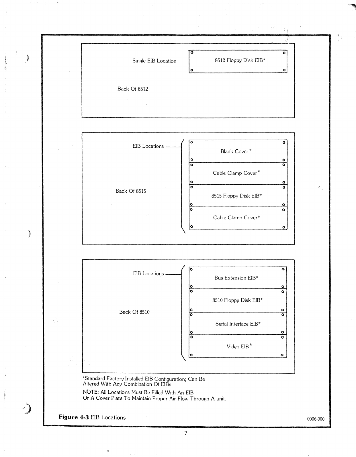
*Standard Factory-Installed
EIB
Configuration; Can
Be
Aitered With Any Combination Of
EIBs.
NOTE:
AIl
Locations Must
Be
Filled With
An
EIB
Or
ACover Plate
Ta
Maintain Proper
Air
Flow Through Aunit.
Figure
4·3
EIB
Locations
7
0006-000
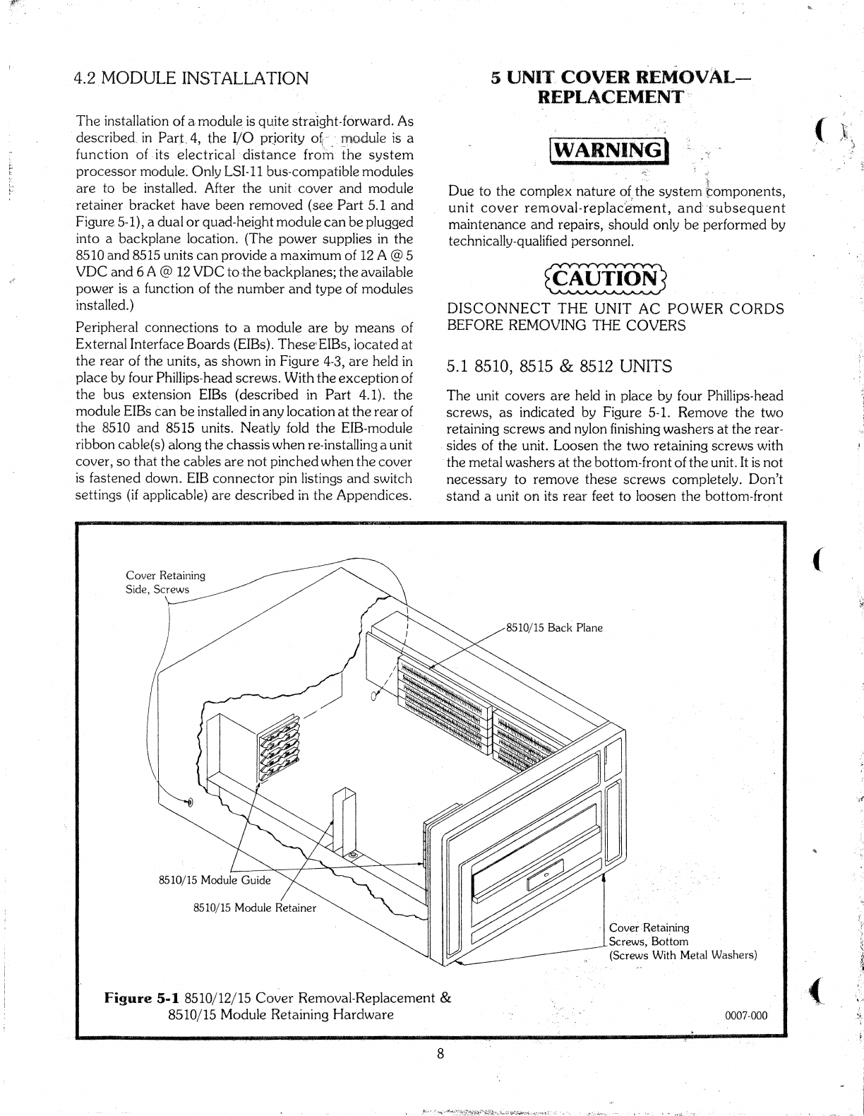
4.2
MODULE
INS~rALLATION
5
UNI1~,
COVER
REMOvAL-
REPLACEMENT
Figure
5·1
8510/12/15
Caver
Removal-Replacement &
8510/15 Module Retaining
Hardware
(
.ô\\.
(
(
0007·000
Cover:Rétaining
Screws,·BoÙom
(Screws With Metal Washers)
(WARNI~~)
*"
Due
ta
the
complex
nature
o(the
system
r.:omponents,
unit
caver
removal-teplac'Èi'ment,
and-
-subsequent
maintenance
and
repairs, should·only
be
perforrned
by
technically-qualified
personnel.
~
DISCONNECT
THE
UNIT
AC
POWER CORDS
BEFORE
REMOVING
THECOVERS
5.1 8510, 8515 &
8512
UNITS
The
unit
covers
are
held
in
place
by
four
Phillips-head
screws,
as
indicated
by
Figure 5-1.
RelTIOVe
the
two
retaining
screws
and
nylon finishing
washers
at
the
rear-
-sicles
of
the
unit.
Loosen
the
two
retaining
screws
with
the
metal
washers
at
the
bottom-front
of
the
unit. It
is
not
necessary
to
remove
these
screws
completely.
Don't
stand
aunit
on
its
rear
feet
to
loosen
the
bottonl-front
Caver
Retaining
Sicle,
Screws
8510/15 Module Retainer
'The installation
of
a-rnoduleis
quite stra'ight-forward.
As
described.
in
Part.4,
the
·1/0
p(jority
o~
..
-_
]1flM);t:1:ule
15
a
function
of -its
electricaldistance
from
the
system
processor
module~
Only
I_SI-11
bus-compatible
modules
are
ta
be
installed. After
the
unit
caver
and
module
retainer
bracket
have
been
removed
(see
Part
5.1
and
Figure 5-1), a
dual
or
quad-height
module
can
be
plugged
into a
backplane
location. (The
power
supplies in
the
8510
and
8515 units
can
provide a
maximum
of 12 A@5
VDC
and
6 A @12
VDC
to-the
backplanes;
the
available
power
i5
afunction
of
the
nurnber
and
type
of
modules
installed.)
Peripheral
connections.
to
a
module
are
by
means
of
External
Interface
Boards
(EIBs).
These'EIBs,
located
at
the
rear
of
the
units,
as
shawn
in
Figure
4-3,
are
held in
place
by
four Phillips-head
screws.
With
the
exception
of
the
bus
extension
EIBs
(described
in
Part
4.1).
the
module EIBs
can
be
installed in
any
location
at
the
rear
of
the
8510
and
8515 units.
Neatly
fold
the
EIB-module
ribbon
cable(s)
along
the
chassis
when
re,·installing aunit
caver,
50
that
the
cables
are
not
pinched
when
the
caver
is
fastened down. EIB
connector
pin listings
and
switch
settings (if applicable)
are
described
in
the
Appendices.
8
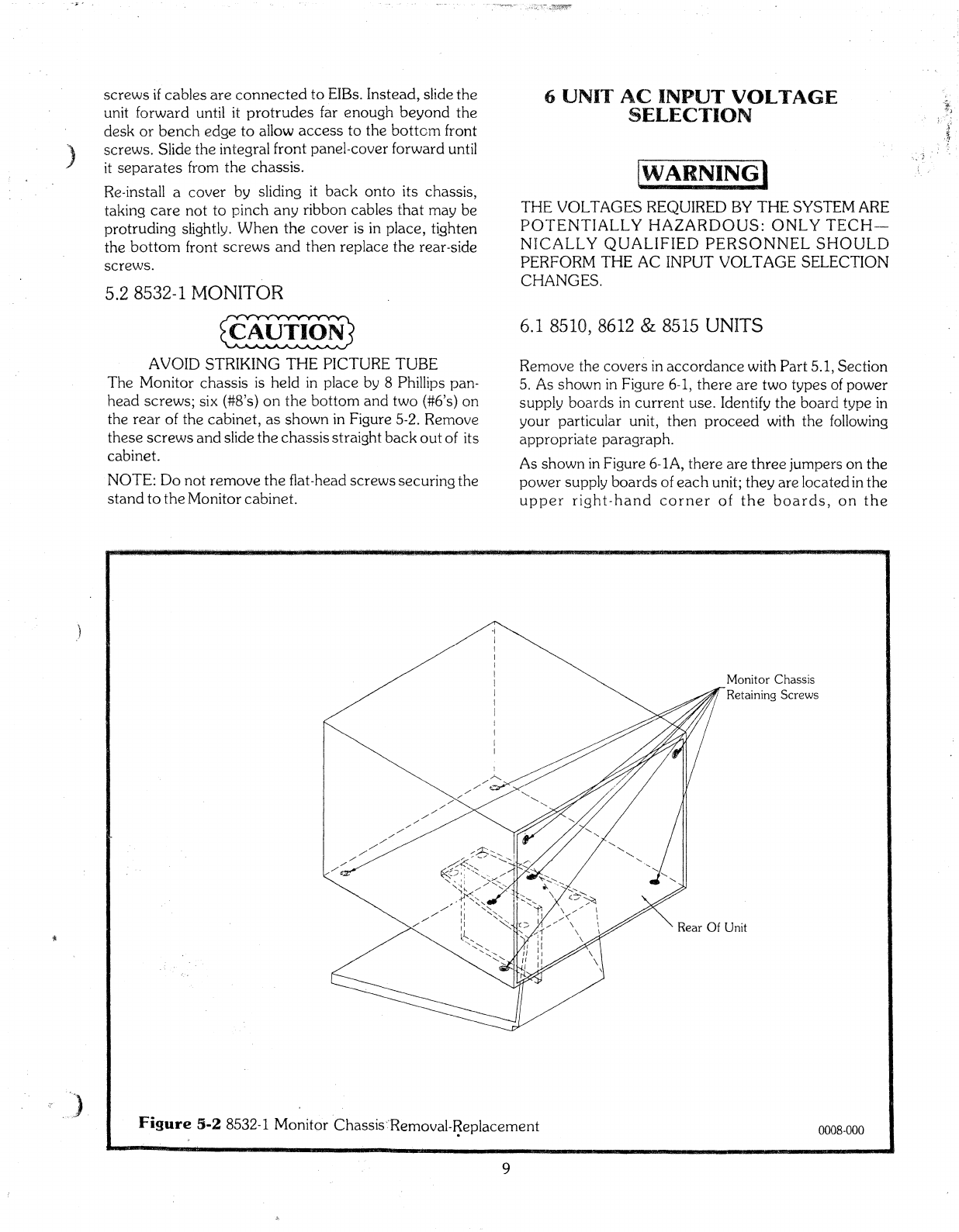
)
screws
if
cables
are
connected
ta
EIBs.
Instead,
slide
the
unit
forward
until it
protrudes
far
enough
beyond
the
desk
or
bench
edge
to
allow
access
to
the
botton1 front
screws.
Slide
the
integral
front
panel~cover
forward
until
it
separates
from
the
chassis.
Re-install a
caver
by
sliding it
back
onto
its
chassis,
taking
care
not
to
pinch
any
ribbon
cables
that
may
be
protruding
slightly. W'hen
the
cover
is in
place,
tighten
thebottom
front
screws
and
then
replace
the rear-side
screws.
5.2 8532-1 MONITOR
~
AVOlD
STRIKING
THE PICTURE TUBE
The
Monitor
chassis
i5
held
in
place
by 8Phillips pan-
head
screws;
six (#8'5)
on
the
bottom
and
two
(#6's)
on
the
rear
of
the
cabinet,
as
shawn
in Figure
5-2.
Renîove
these
screws
and
slide
the
chassis
straight
back
out
of its
cabinet.
NOTE:
Do
not
remove
the
fiat-head
screws
securing
the
stand
to
the
Monitor
cabinet.
6UNIT'
AC
INPUT VOLTAGE
SELECTION
[WARNING)
THE
VOL
TAGES REQUIRED BY THE SYSTEM ARE
pO~rENTIALL
y
HAZARDOUS:
ONL
y
TECf-f-
NIC,ALLyQUALIFIED PERSONNEL
SHOULD
PERFORM 1'HE AC INPUT VOLTAGE SELECTION
CHANGES.
6.1 8510, 8612 &8515 UNITS
Remove
the
cavers
in
accordance
with
Part
5.1,
Section
5.
As
shawn
in Figure
6-1,
there
are
two
types
of
power
supply
boards
in
current
use. Identify
the
board
type
in
your
particular unit,
then
proceed
with
the
following
appropriate
paragraph.
As
shawn
in
Figure
6~
lA,
there
are
three
jumpers
on
the
power
supply
boards
of
each
unit;
the
y
are
locatedin
the
upper
right-hand
corner
of
the
boards,
on
the
Monitor Chassis
7Retaining Screws
""
Rear
Of
Unit
Figure
3·2
8532-1
Monitor
·Chassis·
..
·Removal-~eplacement
9
0008-000

A
~
Hale
And
510t
(For
Access
To' Disk Drive
Chassis
Fastening
Screws)
85JO/15
l;lnit
Powe.r
Supply
Board
----}'
r_----, .240 V!
~
1
=.1
t::j
Sa/60Hz
22~1~
6bo660o~
J23
AC
Line
120
v1
.1:=1
:::'j
c::::
1
(RMS)
lOOV H!
:::t
r=
J
8512 Unit
Power
Supply
Board
~--c:::;---=-.--:::-
1
~;~~.
=
==
~
JI
9<>
09 9099 J8
120
Vib
r=
:::
1
100
v::::l
=:1:::
1
Sû/60Hz AC
____
Line
(RMS)
Typical
Jumper
(
(
0009-000
l
Connector
1 1
J
16
Connector
J
Voltage
Select
Board
Voltage
Select
Board
8510/15 Unit Power Supply
Board
(This Board
TabSurface
Indicates
The
Voltage
~
.
(~,_ele_ct_ed_)
-
----,
~
'8512
Power
Supply Board
~
~\
o~6.
\
sv.{!{!\'l
'<ÇP
/
/'
e'(
~/
\",o\Y
1
/
Hale
And
510t
(For
Access
T0Disk Drive
Chassis
Fastening Screws)
AC, Input Voltage
Select
Board
Location
"
240
AC
Input
Voltage Select
Board
,Figure
6-1
8510/12/15 AC Input Voltage Selection
10

J
component
sicle.
~rhe
8510 &8515
jumper
jacks
are
labeled
J16
through
J'23;
the
8512 jacks
are
labeled
JI
through
J8.
Insert
the
jurnpers
into
the
jack
pairs
that
are
color-banded
together
for a
particular
voltage.
For
instance,
to
operate
an
8512 unit
at
120 V,
the
jumpered
pairs would be: J2
ta
J3;
J4
to J5;
J6
to J7.
As
shawn
in Figure 6-1B, a
printed
wiring
board
is
used
for voltage selection. 'This
board
must
be
inserted
into a
connectar
located
in
the
upper
right-hand
corner
of
the
power
supply
board.
The
connector
is labeled J16.
Ta
select adifferent
ac
input
voltage,
rem
ove
the
board
and
re-insert
it
sa
that
the
desired
voltage
is
indicated
on
the
board
tab
surface
that
is
nearest
ta
the
front
and
top
of
the unit) as
shoVJl1
in
Figure 6-1B.
6.2 8532-1 UNIT
Rernove
the
Monitor
chassis
in
accordance
with
Part
5.2,
Section
5. In Figure 6-2,
the
plugs labeled
Pl
and
P2
contain
the
jumpers.
P2 is actually apair of plugs:
one
is
for 100V &
120\/
operation;
the
other
is
for 220V&24üV
operation.
When
the
pin in
Pl
must
be rnoved, use a
MOLEX
HT
2285
Extractor
Tool, (or equivalent),
ta
rernove
the
pin.
Insert
the
pin in its
alternate
location
until
it
locks
in place.
lOOV
Operation
1.
Insert
the
"120" labeled P2 plug inta
J2.
2.
Move
the
brown-wiredpin in
Pl
ta
location3
of
Pl.
3.
Insert
Pl
into
JI.
120V
Operation
1.
Insert
the
"120" labeled
P2
plug into
J2.
2.
Move
the
brown-wiredpin in
Pl
ta
location 1of
Pl.
3.
Insert
Pl
into
JI.
220V
Operation
1.
Insert
the
"220" labeled P2 plug into J2.
2.
Move
the
brown-wired pin in
Pl
to location 3
of
Pl.
3.
Insert
Pl
inta
JI.
240V
Operation
1.
Insert
the
"220" labeled P2 plug into J2.
2.
Move
the
brown-wired pin in
Pl
ta
location 1of
Pl.
3. Insert
Pl
into
JI.
8532-1
Monitor
Top
View
({j
/~
"'\
\\
C:::::<~
•
-----'
Extractor T
001
(Molex
HT
2285)
Pl
Brn.
Pl
Brn.:
!Grn.
~
For
120
Vand
240
VOperation
Grn.
===;=g;
~
For
100
Vand
220
VOperation
Red·
Red
Figure
6·2
8532-1
AC
Input Voltage
Selection
Il
~p~
1------iJ·,'
,
P2
0010-000

7
UNIT
CHANGES
FOR
59
Hz
&
69Hz
POWERFltEQUENCf'ES
The
pulleys
on
the
disk drive
\-ilc)tors
and
the
drive beIts
of
the
8510,8512
and
8515 units rnust
be
replaced
when
changing from 50 rIz
ta
60
Hz
operation,
or
vice versa.
The
Video
Board
in
the
8510
unit
must
also
be
exchanged.
The
fol1owing TERAK
part
numbers
are
applicable:
Item
50Hz
60
Hz
Video
Board
92-0014-011 92-0014-010
Pulley,
matar
39-0012-001 39-0012-002
Belt, disk drive 39-0013-001 39-0013-002
1.
Remove
the
unit
covers
(see Part 5.1,
Section
5).
2.
Remove
the
8510, 8515 module
retainer
brackets
(see Figure 5-1).
3. Remove the modules from
the
8510 &8515
backpl.anes.
4.
Remove
the
four Phillips-head
screws
that
fasten
adisk drive chassis
to
aunit chassis.
Two
of
these
screws
are
accessed
through
ahale
and
a
510t
in a
power
supply
board
'(see Figure 6-1). The other
two
screws
are
on
the
unit
chassis
sicle
that
i5
opposite
the
power
supply board.
s.
Slide
the
disk drive
chassis
forward until
the
disk
drive
PWB
connectors
can
be
easily
dis-
connected.
Remove
the
disk drive chassis.
6.
Stand
the
disk drive chassis
on
its side
50
that
its
PWB
is
visible. Remave
the
four
slotted
hex.-
agonal
screws
that
fasten
the
PWB
to
the
chassis
housing. Swing
the
PWB
clear of
the
mator
pulley
and
belt drive.
There
are
three
connectors
still
fastened
to
the
PWB;
they
do
not
have
tobe
dis-
connected.
7.
Remove
the
disk drive belt.
8.
Using a1/16
in.
Allen
wrench,
remove
the
small
pulley
on
the
motor
shaft.
9.
In5ta11
the
new pulley
and
new
drive belt.
10.
Re-instal1
the
PWB
and
disk drive unit; re-install
aIl
modules
except
for
the
MemoryVid'eo module.
Il.
Remove
the
ribbon
cable
cannectors
from
Pl,
then
P2,
of
the
Men10ry
board.
12.
Separate
the
Memory
and
Video
boards
by
removing
the
four
corner,
and
two middle, Phil-
lips-heàd
screws
that
hald
the
boards
together.
13.
Fasten
the
Memory
board
to
the.
NEW
Video
board.
14.
Re-connect
the
ribbon
cab
les
ta
P2,
then
Pl,
of
the
Memory
board.
12
15. Re-install
the
Memory-Video rnodule
in
the
8510
backplane,
then
replace
the
module
retainer
bracket.
16. Re-install
the
unit covers. (
(

)
8
BASIC
TROUBLESHOOTING
DlJE
Tü
THE COMPLEXITY
OF
THE
SYS'TEM
AND
TI-IE REQUIREMENT FOR TEST
E(~UI.PMENT,
REPAIRS
AND/OR ADJUSTMENTS
Ta
THE
VAR-
IOUS SUBSYSTEMS
OF
THE8510/a
SHOULD
ONL
y
BE
PERFORMED
SY
QUALIFIED
TECHNîCAL
PERSONNEL
..
The
following
procedures
in Figure
8~
1
are
intended
as
a
fundarrlental guide for problerns
that
could
prevent
the
execution
of
the
Systenl
Acceptance
Tests.
These
procedures
can
help
ta
isoiate aproblen1,
and
in
50
doing, effect a
faster
solution
\tvhen
contacting
TERAK's
Product
Service
Department.
Be
sure
to
include
the
unit
seriaI
numbers
in
any
telephone
or
letters
correspondence
with TERAI<
Product
Service.
WARNING
The voltaqes
required
by
the
system
are
patentially
hazardous.
Only
technically-qualified
personnel
should
perform
the
troubleshooting
stepsenclosed
within this
type
of
box.
Voltage
and
frequency
of
power
source
matches
voltage and
frequency
labels of
aIl
units.
,
Yes
t
r--
No
~_=
_______.1._
...
_
Set
8510, 8512, 8515 &8532-1 units
to
proper
voltage &frequency.
....
--~--~~--
Yes
Yes
N0
't
Check
line fuses,
cords
and
power
source.
Remove
air filters
ta
verify
that
the
fan impellers
rota
te
~
l:eel
y.Air
exhausts
from
851~
only.
,
No
L+
Verify
that
voltage &
frequency
of
power
source
matches
voltage &frequency
setting
of
aIl
units, by
removing
covers
&inspecting
power
supply.
Jo
-
Yes
Air filters
are
clean. Yes
No
[
Clean
air filters.
\--No
Air
exhaust
flow is weak.
Turn
on
system
at
8510
and
(if
present)
8515 units.
Air
is
exhausting
trom
front
panels
of
aIl
(8510,8512
..
and
8515) units.
Power
switch
on
8510 &8515 units
rotates
freely
to
upper
position,
returns
to
center
position
when
released.
No
significant
drag
is
present.
Check
that
aH
floppy disk daisy chain
cab
les
are
propet-ly installed. Relay click
can
be
heard
inside
8532-1
or
8512 units.
'No'
No
Remove
8510
caver.
Check
power
supply
module
by
observing
LED lights. AC
power
indicated
O.K.
,)
Loosen
caver
&realign with
power
switch
rocker.
Yes
!
A
Figure
8-1
Troubleshooting
Guide
No
+
BD
0011-000
13

AB
1
No
Investigate voltage &
frequency
of
local 'power.
Correct
power
supply
voltage
selection,
if
required.
c
y~s
~_--L--
OC
power
is
indicated
O.K~
o
Yes
No
Replace
power
supply Inodule.
~------No-------'
Yes
----,-
.......
-----,----
....
----------------------""""--'-----v..
Verify
that
aIl
PWBs
are
fully
inserted
and
that
the
retaining
clamp
is
mounted
firmly.
Verity
that
aIl
fIat
cables
are
securely
mounted
ta
their
corresponding
edge
connector
on
the
PWBs. Ifrequired,
remove
the
PWBs
and
clean
the
edge
fingerswith
a
clean
cloth
and
a.lcohol,
search
for
components
on
the
PWBs
which may
have
been
damaged
during
shipment,
service,
or
systen1 configuring,
then
remount
in original
arder
and
sec
ure
with
retaining
clamp.
Verify
that
aIl
connectors
in
the
chassis
harness
are
fully
seated.
Relay click
can
be
heard
inside 8532-1 unit,
but
not
inside 8512 unit.
Replace
Happy
disk
controller,
EIB,
or
daisy
chain
cables.
No
Yes 1
____
-1.,_-----.
(
No
Verify
that
keyboard
is
connected
to
video EIB.
Remove
cable
and
rneasure 4.7
ta
5.3
volts
OC
between
pins 1
and
3of
the
video EIB
keyboard
connector.
Remove
the
keyboard
caver.
Verify
that
the
connector
on
the
edge
of
the
keyboard
PWB
is
securely in
place.
Inspect
keyboard
for
damage
during
shipment.
Relay click
can
be
heard
inside 8512 unit,
but
not
inside 8532-1 unit.
Verify distributionof
power
through
system
PWBs,
harness,
EIBs
andcables.
Replace
video
controller~
video EIB,
or
video
cable.
Ye~et
switches. 1
'EML/KBD'
switch
on
the
video EIB
is
set
off
and
left four
switches
on
the
seriaI
interface
are
set
on-
off-an-off.
Type
'lock'
key
on
keyboard.
Red
light
appears
through
key.
Type
'shift'
key
on
keyboard.
Red
light
is
extinguished.
"-'-----.
-----~------~------
r..---_-
~Iro--_
..
;_----_-------J
\'es
......--
f
____
Mount
system
acceptance
disk
inta
8510
unit.
Diskette
bottoms
into drive with aclick,
stays
in
place
and
drive
door
closes
and
latches.
No
Yes
!
E(
Figure
8-1
Troubleshooting
Guide
0011-000
14
Other manuals for 8510/a
1
Table of contents
Other Terak Desktop manuals

Popular Desktop manuals by other brands


Dell
Dell OptiPlex 3090 Ultra Setup and specifications

HP
HP A320m - Pavilion - 256 MB RAM Support guide

Compaq
Compaq AP750 - Professional - 256 MB RAM Installation and configuration

Sony
Sony VPCL117FX - Vaio L Series All-in-one Touch... quick start guide

Panasonic
Panasonic CF-31GT2AXDE operating instructions

Zotac
Zotac ZBOX PRO ZP-QK7P3000 user manual