Terak 8510/a User manual
tErak
MODEL
8510/a
INSTALLATION
INSTRUCTIONS
TERAK
Publication
Number
50-0000-001
REV
B
COPYRIGHT
(C)
TERAK
CORPORATION
1979
14405
NORTH
SCOTTSDALE
ROAD
•
SCOTTSDALE,
ARIZONA
85254
•
(602)991-1580
The
TERAK
Model
8510
Data
Processor
is
a
self-contained,
disk
based
minicomputer
system.
Specific
design
features
include
compactness,
%
ease
of
operation
and
low
operating/maintenance
costs.
The
following
information
is
intended
as
a
general
guide
to
the
characteristics,
operation
and
maintenance.
For
detailed
specifications
refer
to
software
and
hardware
technical
manuals
and
user
applications/operator
instruction
manuals.
GENERAL:
The
8510
operates
on
standard
line
voltages
(105-120V/60Hz)
and
comes
equipped
with
a
71
line
cord
with
molded
plugs
at
both
ends.
The
line
cord must
always
be
plugged
into
a
grounded
A.C.
receptacle.
Although
it
is
recommended
that
the
power
on/off
switch
located
on
the
front
panel
be
in
the
"off11
position
whenever
the
line cord
is
being
connected/disconnected,
the
8510
is
designed
such
that
it
will
not
be
damaged
nor
will
data
be
destroyed
on
a
disk
should
the
unit
be
connected
or
disconnected
with
the
power
switch
in
the
"on"
position.
(NOTE:
If
data
is
being
written
onto
the
disk
when
power
is
removed
from
the
system,
the
data
on
that
sector
of
the
disk
can
be
lost.
The
formatting
data
on
the
disk
will
not,
however,
be
destroyed.)
Any
power
interruption
will
cause
an
orderly
shut-down
of
the
system
electronics
and
the
system
will
automatically
restart
upon
restoration
of
power.
The
8510
does
not
require
any
special
operating
environment
and
is
designed
for
operation
in
most
environments
where
people
are
comfortable.
Excessive
temperature,
humidity
and
dust
laden
air
can
be
harmful.
Specific
ranges
of
environmental
operating
limits
are
covered
under
the
technical
specifications.
The
8510
is
designed
using
low-power components
to
reduce
the
operating
cost
and
keep
component
temperatures
to
a
minimum,
assuring
their
stability
and
longevity
of
service.
The
entire
unit
consumes
less
than
100
watts
of
power
during
operation.
Even
so,
to
minimize
component
damaging
heat
build-up,
the
entire
inner
chassis
and
front
panel
are
constructed
to
provide
flow-through
ventilation
around
and
over
all
components
from
the
quiet,
efficient
ventilating
fan
mounted
at
the
rear
of
the
chassis.
This
fan
completely
replaces
the
air
inside
the
unit
more
than
35
times
each
minute.
To
prohibit
the
introduction
of
forfegn
material,
and
as
an
added
safety
factor,
the
fan
mounting
supports
a
"fine
particle"
filter.
The
filter
is
externally
removable
permitting
cleaning
and
replacement
without
internal
access
to
the
unit.
The
filter
should
be
removed
periodically
and
gently
washed
in
warm
water.
Make
certain
that
the
filter
is
completely
dry
before
replacing.
Conditions
will
vary
depending
upon
location
of
the
unit
and
the
environ
ment,
but
filter
cleaning
is
recommended
once
every three
months.
The
8510,
though
small
and
portable,
is
a
delicate
piece
of
electronic
equipment
and
should
be
treated
accrodingly.
Do
not
expose
to
extremes
of
heat
or
cold
and
protect
it
against
moisture
and
dust.
Do
not
it
to
excessive
shock.
A
damp
rag
should
be
used
lightly
on
-1-
outside
paint
surfaces
if
cleaning
is
necessary.
TERMINAL
CONNECTIONS:
The
Model
8510
Serial
Interface
Connector
Panel
provides
for
interface
through
EIA
Standard
RS-232-C
or
20ma
current
loop.
Both
female
and
male
RS-232-C
connectors
are
provided
to
enable
the
machine
to
operate
as
data
communications
equipment
or
data
terminal
equipment
as
defined
in
the
Electronic
Industries
Assoication
(EIA)
RS-232-C
Standards.
The
panel
aslo
contains
two
sets
of
eight
miniature
switches
to
select
baud
rates,
parity
and
other
features.
Fourteen
rates
are
selectable
from
50
to
19,200
baud.
ADDITIONAL
DISK
DRIVES:
The
Model
8510
is
provided
with
a
disk
drive
external
interface
board
(EIB)
as
standard equipment.
This
EIB
allows
addition
of
a
Model
8512
Flexible
Disk
Subsystem
without
any
internal
modifications
to
the
8510.
Up to
three
8512's
can
be
added
to
the
system
merely
by
plugging
in
an
interconnect
cable
from
the
8510
to
an
8512
and
then
from
8512
to
8512.
All
power
on/off
and
control
signals
for the
8512's
are
controlled
from
the
8510.
The
system
terminator
should
be
left
in
place
on
the
8510
disk
drive
EIB.
OPERATING
INSTRUCTIONS:
The
Model
8510
Data
Processor
has
been
designed
for
ease
of
operation
even
by
persons
with
no
prior
computer
training.
The
keyboard/display
terminal
connection
is
straight-forward
and the
operator
need
only
turn
the
power switch
on to
begin
operation.
NOTE:
Prior
to
beginning
operation,
the
operator
should
read
the
section
of
this
manual
dealing
with
DISKETTE
HANDLING
to
insure
familiarity
with
proper
loading
and
unloading
procedures.
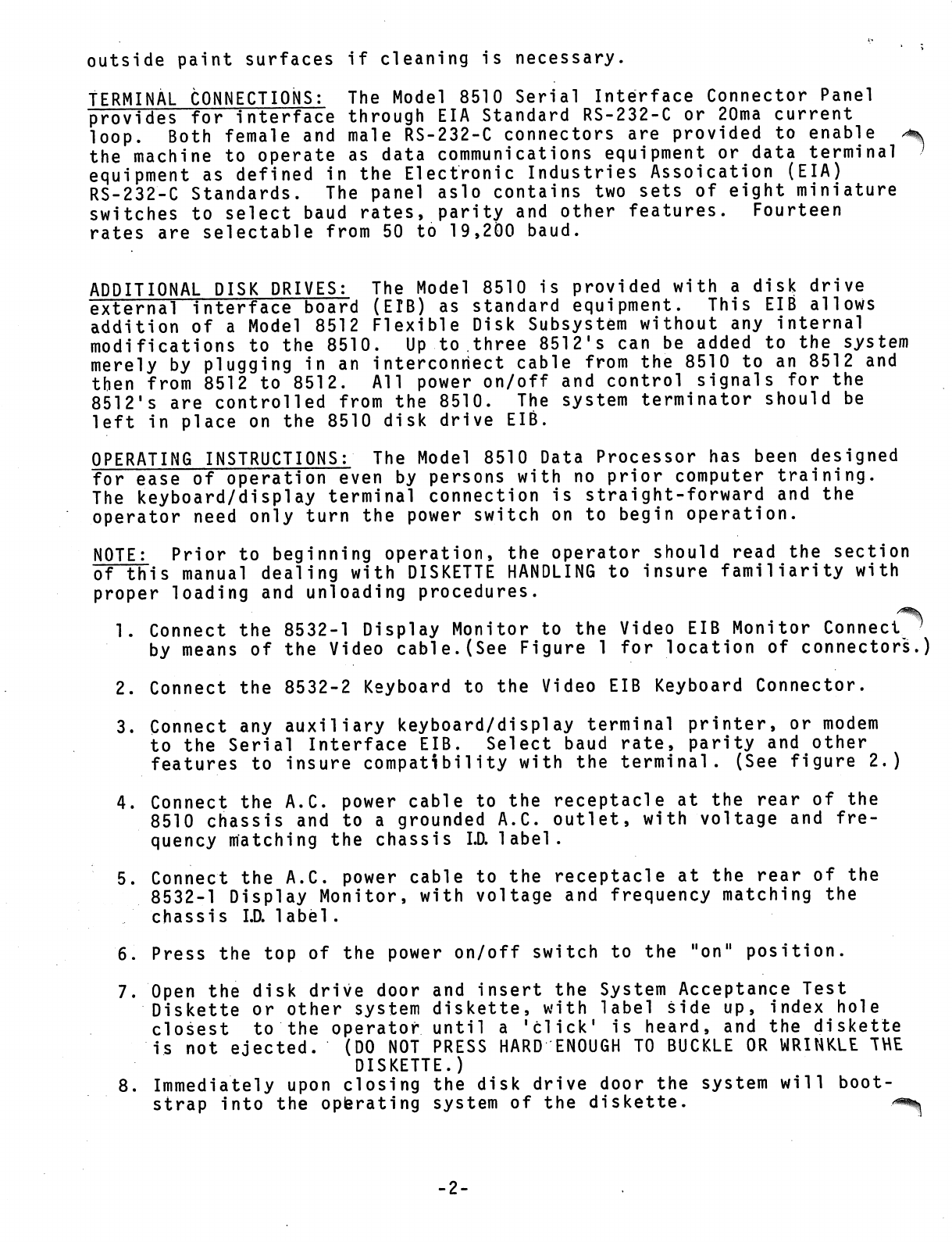
1.
Connect
the
8532-1
Display
Monitor
to
the
Video
EIB
Monitor
Connect
by
means
of
the
Video
cable.(See
Figure
1
for
location
of
connectors.)
2.
Connect
the
8532-2
Keyboard
to
the
Video
EIB
Keyboard
Connector.
3.
Connect
any
auxiliary
keyboard/display
terminal
printer,
or
modem
to
the
Serial
Interface
EIB.
Select
baud
rate,
parity
and
other
features
to
insure
compatibility
with
the
terminal.
(See
figure
2.)
4.
Connect
the
A.C.
power cable
to
the
receptacle
at
the
rear
of
the
8510
chassis
and
to
a
grounded
A.C.
outlet,
with
voltage
and
fre
quency
matching
the
chassis
I.D.
label.
5.
Connect
the
A.C.
power
cable
to
the
receptacle
at the
rear
of
the
8532-1
Display
Monitor,
with
voltage
and
frequency
matching
the
chassis
I.D.
label
.
6.
Press
the
top
of
the
power
on/off
switch
to
the
"on"
position.
7.
Open
the
disk
drive
door
and
insert
the
System
Acceptance
Test
Diskette
or
other
system
diskette,
with
label
side
up,
index
hole
closest
to
the
operator
until
a
'click'
is
heard,
and
the
diskette
is
not
ejected.
(DO
NOT
PRESS
HARD
ENOUGH
TO
BUCKLE
OR
WRINKLE
THE
DISKETTE.)
8.
Immediately
upon
closing
the
disk
drive
door
the
system
will
boot
strap
into
the
operating
system
of
the
diskette.
-2-

NOTE:
Should
the
system
fail
to
bootstrap
or
should
you
wish
to
re-bootstrap
the
system,
momentarily
press
the top
of
the
power
on/off
switch.
The
system
is
reset
when
the
switch
is
pressed
and
re-bootstrapped
when
the
switch
is
released,
This
can
be
accomplished
in
a
quick
press/release
motion.
DISKETTE
HANDLING
The
Diskette
consists
of
the
flexible
disk
encased
in
a
plastic
jacket.
When
not
in
use the
Diskette
is
always
stored
in
a
protective
envelope.
The
storage
envelope
provides
protection
from
dust
and
contaminants
which
can
cause
damage
to
the
Diskette
surface
and loss
or
distortion
of
data.
To
protect
the
Diskette,
these
precautionary
procedures
should
be
followed:
1.
Return
the
Diskette
to
its
storage
envelope
whenever
it is
removed
from
the
disk
drive.
2.
Store
Diskettes
vertically.
3.
Keep
Diskettes
away
from
magnetic
fields
and
from
ferromagnetic
materials
which
might
become
magnetized.
Strong
magnetic
fields
can
destroy
recorded
data
on
the
Diskette,
and
can
remove
the
Preformatting
on
the
diskette;
such
that
it
cannot
store
data.
4
-
Diskettes
such
that
it
cannot
store
data.
Replace
storage
envelopes
when
they
become
worn,
cracked
or
distorted.
Envelopes
are
designed
to
protect
the
Diskettes.
Do
not
write
on
the
Diskette
with
a
lead
pencil
or
ball-point
pen.
Use
a
felt
tip
pen.
Use
labels
with
a
non
permanent
adhesive.
Never
attempt
to
remove
labels
which
use
a
permanent
adhesive.
Do
not
smoke
while
handling
the
Diskette.
Heat
and
contamination
from
a
carelessly
dropped
ash can
damage
the
Diskette.
Do
not
expose Diskettes
to
heat
or
sunlight.
The
read/write
head
cannot
properly
track
a
warped
disk.
Do
not
touch
or
attempt
to
clean
the
disk surface.
Abrasions
may
cause
loss
of
stored
data.
-3-

DISKETTE
LOADING
AND
UNLOADING
CAUTION:
To
avoid
possible
damage
to
the
Diskette,
insure
that
the
Diskette
is
secured
in
the
unit
before
closing
the
disk
drive
door.
Slide
the
Diskette
into
the
open
mouth
of
the
drive
until
a
"click11
sound
is
heard.
Release
the
Diskette
to
ensure
that
it
does
not eject.
These
procedures
should
be
followed
when
loading
and
unloading
a
Diskette:
TO
LOAD
1.
Always
insure
that
unit
is
turned
on
before
inserting
a
Diskette.
2.
Open
the
drive
door
by
lifting
up
using
the
"lip11
on
the
door.
3.
Carefully
remove
the
Diskette
from
its
storage
envelope.
4.
Insert
the
Diskette
with
the
label
facing
up
and
the
index
hole
closest
to
the
operator
(see
Figure
1).
5.
Slide
the
Diskette
into
the
open
mouth
of
the
drive
until
a
"click"
sound
is
heard.
Then
release
the
Diskette
and
ensure
that
it
does
not
eject.
6.
Close
the
drive
door
gently.
TO
UNLOAD
1.
Depress
the
disk
release
control
located under
the
disk
drive
door.
2.
Remove
the
Diskette.
3.
Return
the
Diskette
to
its
protective
storage
envelope.
4.
Gently
close
the
door
(unless
other
Diskettes
are
to
be
loaded).
-4-

AIR
FILTER
(CLEAN
PERIODICALLY)
DISK
DRIVE
TERMINATOR
(DO
NOT-MOVE)
A.C.
POWER
RECEPTICLE
DISK
DRIVE
EIB
DAISY
CHAIN
CABLE
CONNECTOR
FLOPPY
DISK
EIB
SPARE
EIB
SERIAL
INTERFACE
EIB
IDEO
EIB
VIDEO
EIB
MONITOR
CABLE
CONNECTOR
VIDEO
EIB
KEYBOARD
CABLE
CONNECTOR
SYSTEM
I.D.
LABEL
(CHECK
FOR
A.C.
POWER
VOLTAGE
AND
FREQUENCY
REQUIREMENTS)
FIGURE
1
SERIAL
INTERFACE
EIB
SWITCHES
Setting
OFF OFF
ON
OFF
ON
OFF
OFF
OFF
ON
ON
ON
ON
OFF
ON
OFF
ON
ON
ON
ON
OFF
OFF
OFF
OFF
OFF
ON
OFF
OFF
OFF
ON
OFF
OFF
OFF
Unit
Adults
0
177560
1
177520
2
177530
3
177570
4
176520
5
176530
6
176560
7
176570
Notes:
Never
set
two
serial
interfaces
to
the
same
unit
number.
Unit
0
(if
selected)
requires
Video
EIB
switch
to
be
set
to
"ALT".
ON
ON
OFF
OFF
OFF
OFF
OFF
OFF
ON
ON
OFF
ON
ON
ON
FIGURE
Setting
ON
ON
ON
OFF
ON
OFF
ON
OFF
ON
OFF
OFF
ON
OFF
OFF
ON
2
OFF
OFF
ON
ON
OFF
OFF
ON
OFF
ON
OFF
OFF
ON
ON
OFF
OFF
OFF
ON
OFF
ON
ON
OFF
OFF
OFF
OFF
ON
ON
ON
Rate
50
75
110
134
150
200
300
600
1200
1800
2400
4800
9600
19200
-5-
Other manuals for 8510/a
1
Table of contents
Other Terak Desktop manuals


