TERASAKI TemTripPRO User manual

-1- KRB-5426c
TemTripPRO
MOTOR PROTECTIVE RELAY
(Type PRS-1S)
INSTRUCTION MANUAL
Be sure to read this instruction manual before using the product.
Keep this manual handy and safely.
Make sure that the product is set, adjusted or tested by a competent person.

KRB-5426c-2-
1. Safety Notices................................................................................................................................................................. 3
2. Specifications.................................................................................................................................................................. 4
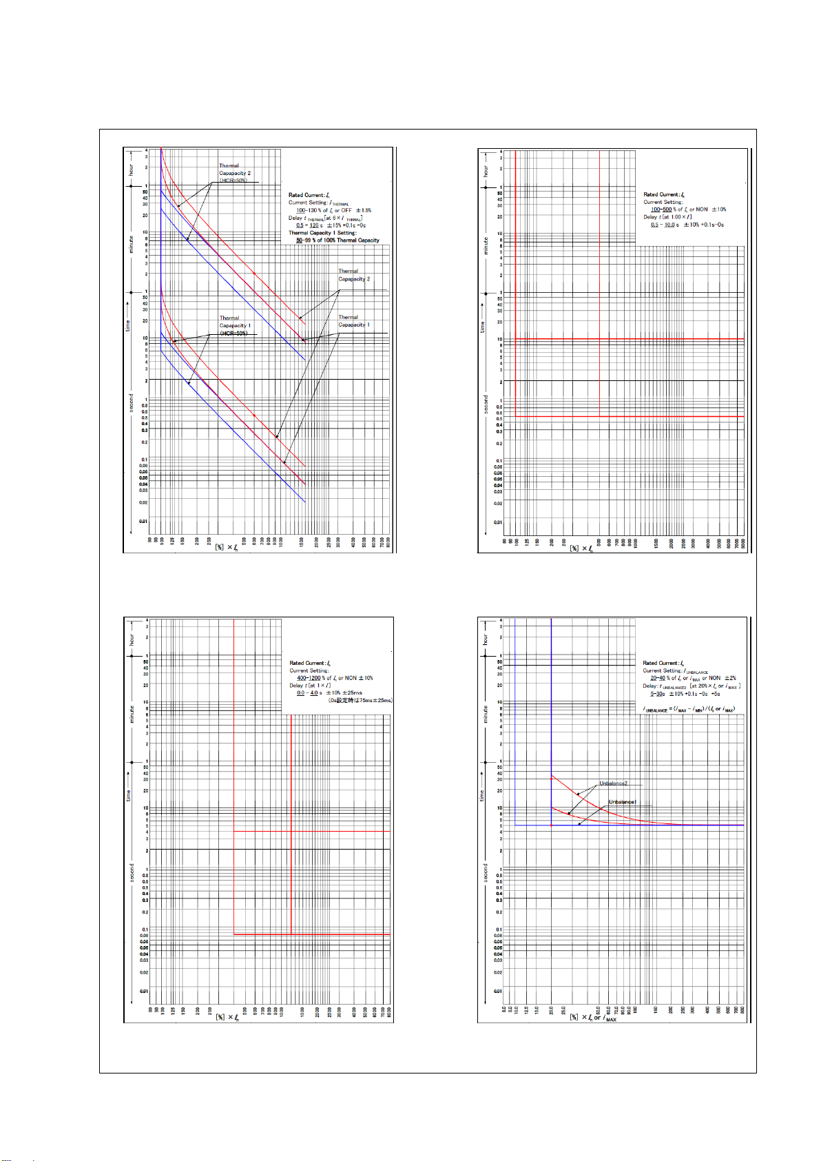
3. Characteristics................................................................................................................................................................ 5
4. Component Identifications ............................................................................................................................................ 10
5. Installation......................................................................................................................................................................11
6. Connection.................................................................................................................................................................... 12
6-1. Circuits and Ratings.......................................................................................................................................... 12
6-2. Terminal Connection Procedure........................................................................................................................ 13
7. How to Display Measurements and Make Settings....................................................................................................... 14
7-1. General ............................................................................................................................................................. 14
7-2. Navigation to Each Setting Item Screen After Power ON (from INI-A-1 through to MA-A-1)............................. 15
7-3. Navigating between Measured Value Display Item Screens (from MO-A-1 through to MO-G-2)...................... 16
7-4. Navigating between Characteristic Value Setting Item Screens (from S-A-1 through to S-D-1)........................ 18
7-4-1. Navigating between setup item screens (from S-A-1 through to SU-L-1)............................................... 20
7-4-2. Navigating between password setting/authentication screens (from SU-L-1 through to P-A-4).............. 23
7-4-3. Navigating between setting item screens (from S-A-1 through to ST-A2-3①)........................................ 25
7-4-3-1. Navigating between setting item screens (from S-B-2①through to ST-B2-1)............................. 27
7-4-3-2. Navigating between setting item screens (from S-B-2②through to ST-C2-1).............................. 29
7-4-3-3. Navigating between setting item screens (from S-C-1 through to ST-L-1).................................... 31
7-4-3-4. Navigating between setting item screens (from S-D-1 through to ST-W-1)................................... 39
7-5. Navigating between Maintenance Item Screens (from MA-A-1 through to MA-I-2)........................................... 47
7-6. Screen Transition in the Event of Trip or Alarm (TR-A-1, AL-A-1) ..................................................................... 52
7-7. Function Test and Relay Test (from MA-B-1 to AL-A-1)..................................................................................... 53
7-8. History and Trip/Alarm Activation Display Screens............................................................................................ 55
7-9. Responses to Abnormal Events ........................................................................................................................ 56
Table of Contents

-3- KRB-5426c
1. Safety Notices
Thank you for purchasing the TERASAKI motor protective relay, TemTrip PRO.
This chapter contains important safety information.
Be sure to carefully read these safety notices, instructions in this manual, and other documents accompanying the motor protective
relay (herein referred to as the "protective relay") to familiarize yourself with safe and correct procedures or practices before using
the protective relay.
Safety notices in this manual are categorized as “CAUTION” in terms of the hazard level:
CAUTION: A caution notice with this symbol indicates a potentially hazardous situation which, if not avoided, may result in
minor or moderate injury and/or property damage.
Note that failure to observe a caution notice could result in serious injury/damage in some situations. Because safety notices contain
important information, be sure to read and observe them.
CAUTION
Common to transportation, operations and storage
Do not store the product in a place where it is subject to direct sunlight, high temperatures, high humidity, dusty air, corrosive
gases, strong vibration and shock, or other unusual conditions. (Storage temperature: -25°C to 75°C).
Maintain the ambient temperature in a range of -10°C to 55°C and the ambient humidity in a range of 30% to 90% RH (15°C to
35°C without condensation). Failure to do so may result in malfunction.
Before cleaning, first turn the power OFF, use towels twisted to be dry after soaked with warm water. Use of diluents or other
organic solvents may dissolve or discolor the product surface
Transportation
Do not drop or impact the product. Carefully handle the product as this is an electronic device. Failure to do so may result in
malfunction.
Operations
Make sure that the product is set, adjusted or tested by a competent person.
After completion of a function check involving setting changes, be sure to return the settings to the original values. Failure to do
so may cause a burnout or fire.
Packing items
① TemTrip PRO
⑦Mounting tool: x2
Packing items
Q’ty
①
TemTrip PRO
1
②
Connector 2pin
1
③
Connector 3pin (1)
2*1
④
Connector 3pin (2)
1
⑤
Connector 10pin
1
⑥
Connector 12pin
2
⑦
Mounting tool
2
Connectors: 7 connectors (8 connectors for
specification with communication function)
②
⑥
③
⑤
④
*1:For specification with communication function, three of them
packaged.

KRB-5426c-4-
2. Specifications
Specifications of the type PRS-1S protective relay are shown in Table 1 below.
Table 1 Specifications of protective relay (●: Standard feature, ○: Option)
Presence/abse
nce
Reference section
Protective function
Applied current anomaly detection setting*2
●
3, 7-4-3
Overload element detection *1 *2
●
3, 7-4-3-1
Short-circuit protection setting*3
●
3, 7-4-3-1
Motor heating detection setting*1
●
3, 7-4-3-3
Unbalanced current trip (UB) *1
●
3, 7-4-3-3
Motor startup time, startup count *1
●
3, 7-4-3-3
Directional ground overcurrent trip (DGR) *1
●
3, 7-4-3-3
Temperature sensor detection setting*1
●
3, 7-4-3-4
Open-phase protection*1
●
3, 7-4-3-4
Undercurrent protection (LC/HC) *1
●
3, 7-4-3-4
Negative phase sequence current protection setting*1
●
3, 7-4-3-4
External anomaly detection setting*1
●
3, 7-4-3-4
Operation indication
LED indication and LCD screen
●
4
Measurement/event indication
Present current (respective phase current)
●
3, 7-3
Leakage current and voltage values
●
3, 7-3
Temperature indication
●
3, 7-3
Alarm event log (100 events) *4
●
3, 7-6, 7-7
Trip event log (100 events) *4
●
3, 7-6, 7-7
Trip/alarm event log (200 events) *5
●
3, 7-6, 7-7
Communication function *5
○
3, 7-5
Control power supply
Required
-
*1: Two modes are available; one where the protective relay is tripped and operation indication is provided and the other where the
protective relay is not tripped and no operation indication is provided.
*2: Either of the following modes is available; one where the protective relay is not tripped and only operation indication is
provided and the other where the protective relay is not tripped and no operation indication is provided.
*3: Two modes are available; one where the protective relay is tripped and the other where the protective relay is not tripped
*4: Logs 100 pieces of data each for trip and alarm events and allows the user to display the cause, concerned value and operating
time of each event.
*5: Logs 200 pieces of data each for trip, alarm, reset, and other events. The details (concerned value and operating time) need
confirmation of each event log.
*6: The data format is Modbus RTU.
Table 1-1 General specifications of protective relay
Control voltage
110VDC (82.5VDC –143VDC)
VA consumption
5VA
External dimensions
W96 × H144 × D116 mm (including the terminals on the back)
Operating temperature
-10℃ –+55℃
Storage temperature
-25℃ –+75℃
Humidity
95% or lower (no condensation)
Mass
0.7kg
Applicable standards
IEC60255: Measuring relays and protection equipment
IEC60947-4-1 Part4: Contactors and motor-starters

-5- KRB-5426c
3. Characteristics
3-1. Representation Format of Type
Type: PRS-1S N T1
① ② ③
Specification
Symbol
Description
Standard
①Communication function
N
Without communication function
C
With communication function
②Temperature sensor type
T
THERMISTOR
P
RTD
③CT rated current
1
1A
5
5A
3-2. About Characteristic Settings
Table 2 shows the characteristic settings of the protective relay.
Table 2 Characteristic settings parameter
Protective function
Selection
Setting range
STEP
Remarks
Frequency
50Hz / 60Hz
-
-
-
CT rated current (Ict)
(Sec.) 1A/5A
(Pri.): (10.0 –1500) A
1A
-
Rated current (FLC) (In)
-
(0.30 –1.00) X Ict A
0.1A
However,
0.30 x Ict or more
Zero-phase voltage
190V (Not adjustable)
Trip activation time setting
-
(4.00 –10.00) X In or
OFF
0.10
-
Input setting 1 (IN1)
Remote Reset /
External fault 1 (NO) /
External fault 1 (NC)
-
-
-
Input setting 2 (IN2)
Remote Reset /
External fault 2 (NO) /
External fault 2 (NC)
-
-
-
AN. OUT ADJ (4-20)
-
(90.0 –110.0)%
0.1%
4-mA (0 output)
adjustment
-
(90.0 –110.0)%
0.1%
20-mA output
adjustment
-
(1.00 –1.20) X Ict
0.01
Full range setting
Transmission address
setting
(1-31)
-
-
-
Transmission rate setting
9600 / 19200 (bps)
-
-
-
Parity setting
NONE / ODD / EVEN
-
-
-
RY contact output
HOLD / PULSE
-
-
Selectable for each RY
I1, I2, I3 adjustment
-
90.0 –110.0%
0.1%
Use this function to
adjust the value on the
LCD screen to the
customer’s reference
value without affecting
the protection
characteristics.
Date/time setting
Year, month, day, hour,
and minute
-
-
-

KRB-5426c-6-
Table 2 Characteristic settings parameter (continued)
Protective function
Selection
Setting range
STEP
Remarks
Motor startup time
detection setting
TRIP / ALARM /
OFF
(1 –250)s
1s ±2%+0.1-0s
(When the calculated value
is time equal to or greater
than 1.10 x overload pick
up)
Motor startup count
detection setting
TRIP / ALARM /
OFF
(1 –10)
1
"Too Many Starts" is
displayed when startup count
is detected during the period
specified for STARTS
PERIOD.
Detection time
-
(1 –60) min
1min
-
Undercurrent
protection setting
(LVL1)
(Low current)
TRIP / ALARM /
OFF
(0.20 –0.90) X In
(0.5,1 –60)s
0.01 ±3%
(relative to the CT rating)
1s ±5%+0.1-0s
The relay is activated when a
current value above the set
value continues for the
specified time limit or longer
with the motor in a running
state.
Startup disabled time
-
(0.0 –30.0)s
0.5s +0.1-0s
-
DEAD BAND
-
(0.005 –0.050) X Ict
(when the motor is
about to turn ON)
0.001
-
Undercurrent
protection setting
(LVL2)
(High current)
TRIP / ALARM /
OFF
(0.20 –1.50) X In
(0.5, 1 –60)s
0.01±3%
(relative to the CT rating)
1s ±5%+0.1-0s
The relay is activated when a
current value above the set
value continues for the
specified time limit or longer
with the motor in a running
state.
Startup disabled time
-
(0.0 –30.0)s
0.5s +0.1-0s
-
DEAD BAND
-
(0.005 –0.050) X Ict
(when the motor is
about to turn OFF)
0.001
-
Applied current
anomaly detection
setting
Overload element
ALARM / OFF
(1.00 –1.50) X In
0.01 ±2.0%
The relay is activated when
the mean current value
exceeds this set current value
for five seconds or longer with
the motor in a running state.
Overload protection
TRIP / ALARM /
OFF
(1.00 –5.00) X In
(0.5 –10.0)s
0.01 ± 10%
0.1s ±10% +0.1-0s
This function is for JAM/stall
protection.
The relay is activated when
the mean current value
exceeds this set current value
for five seconds or longer with
the motor in a running state.

-7- KRB-5426c
Table 2 Characteristic settings parameter (continued)
Protective
function
Selection
Setting range
STEP
Remarks
Short-circuit
protection
TRIP / OFF
(4.00 –12.00) X In
(0.0 –4.0)s
0.10 ±10%
0.1s ±10%±25ms
(When 0 is set: 75 ±25 ms)
This function is for short-circuit
protection. It can be activated when
the motor is started or running.
Short-circuit protection becomes
locked if the maximum phase current
exceeds the trip activation disable
setting when the motor is started or
running.
Overload pick up
(The following three
elements are used to
calculate thermal
capacity.)
-
(1.00 –1.30) X In
0.01 ±2.0%
Current setting for motor heating
detection setting (LVL1/LVL2)
Trips based on motor heating
detection setting (LVL1/LVL2) are
not activated when the current value
is equal to or lower than this current
setting.
If the current value reaches or
exceeds this current setting, the relay
will be activated according to the
time limit dependent on the present
current value, thermal capacity, or
T6X TIME.
Trip activation
time setting
-
(0.5 –120.0)s
0.5s ±15%+0.1s-0s
This element sets trip activation time
for “cold” motor at a current value six
times the value specified for
OVERLOAD PICKUP.
Motor heat
capacity ratio
-
(0.20 –1.00) X
Motor heat capacity
0.01
This element sets the ratio of the
motor heat capacity applied to "hot"
motor and the motor heat capacity
applied to "cold" motor.
Motor time
constant ratio
-
(1 –15)
1
This element sets the ratio of the time
constant of cooling for a stopped
motor and the time constant of
heating/cooling for a running motor.
Motor heating
detection setting
(LVL1)
TRIP /
ALARM / OFF
(0.50 –0.99) X max
Thermal capacity
0.01
This function simulates motor heating
status.
Heating is related to the square of the
maximum phase current. The
percentage of cooling is directly
related to the heating status and
present value of the motor.
Motor heating
detection setting
(LVL2)
TRIP /
ALARM / OFF
-
-
Motor heat capacity 100% is equal to
motor drive at the maximum
allowable temperature. In this state,
tripping must be activated. (LvL2)
*1: Motor START state (starting state) refers to the state in which the root-means-square (RMS) of three-phase current values
exceeds the value of overload pick up×110% (from the state in which the current value is less than Ict×15%) once and then falls
below the value of overload pickup×110% once.
*2: Motor RUN state (running state) refers to the state in which the current value falls below the value of Ict×8% after the motor
starting state ends. The motor running state also applies when the current value falls below the value of overload pickup×110%
once and then exceeds the value of pick up×110% again before it falls below the value of Ict×15%.
*3: Motor STOP state (stopped state) refers to a pre-startup state in which the root-means-square (RMS) of three-phase current
values does not yet exceed the value of overload pickup×110%. It also includes a state in which the operating state is
"complete".

KRB-5426c-8-
Table 2 Characteristic settings parameter (continued)
Protective
function
Selection
Setting range
STEP
Remarks
Unbalanced
current protection
setting (LVL1)
TRIP / ALARM / OFF
-
-
"Unbalanced current
protection setting (LVL1)" is
50% ±2% (relative to the set
value) of "Unbalanced current
protection setting (LVL2)".
Time limit: 5 s (Not
adjustable)
Unbalanced
current protection
setting (LVL2)
MAX T
TRIP / ALARM / OFF
(0.20 –0.40) ×
("In" or maximum
phase current,
whichever is greater)
0.01 ±2%
(relative to the set value)
Characteristic: I2t = C (C = 0.01)
* Set time limit (MAX T in
"Unbalanced current protection
setting (LVL2)")
-
(5 –30)s
1s (±10%)+0.1s-0s
Time limit is applicable when
10% is set
Time limit is counted after
"Unbalanced current
protection setting (LVL1)" is
activated.
Directional Ground
fault detection
current
TRIP / ALARM / OFF
(1.0 –10.0)mA
0.1mA±10%
Secondary
Directional Ground
fault detection
voltage
-
(0.050 –0.150) X
V0n
0.001 ±25%
V0n: 190V
Phase
-
(0 –90)deg or OFF
10deg
Setting “OFF” means that no
direction is set.
Phase difference
-
(0.1 –10.0)s
0.1s (±15%)+0.1-0s
Phase difference between -3
V and I0
The relay is activated when I0
is within 90° of -3V.
Temperature
sensor
RTD / THERMISTOR
-
-
*1
Type
NTC / PTC
-
-
*2
Temperature
sensor
detection
(LVL1)
TRIP / ALARM / OFF
(0 –250)℃
1℃ (±1%)±1℃
TEMP1 (When RTD is set)
(0.1 –30.0)kΩ
0.1kΩ (±5%)±0.1kΩ
OHM1 (When
THERMISTOR is set)
(0 –60)s
1s (±5%)+0.1-0s
Temperature
sensor
detection
(LVL2)
TRIP / ALARM / OFF
(0 –250)℃
1℃ (±1%)±1℃
TEMP2 (When RTD is set)
(0.1 –30.0)kΩ
0.1kΩ (±5%)±0.1kΩ
OHM2 (When
THERMISTOR is set)
(0 –60)s
1s (±5%)+0.1-0s
Negative phase
sequence current
protection
TRIP / ALARM / OFF
-
-
Checked within 0.5 s
The relay is activated when the
current value reaches or exceeds
the "overload pick up" setting.
External anomaly
detection 1
TRIP / ALARM / OFF
-
-
This function is enabled only
when specified in "Input setting 1
(IN1)".
External anomaly
detection 2
TRIP / ALARM / OFF
-
-
This function is enabled only
when specified in "Input setting 2
(IN2)".
Open-phase
protection
TRIP / ALARM / OFF
-
-
The relay is activated when
the current value is equal to or
less than 50% of the set
current value (In) .
Current
unbalance factor
(0.30 –0.65) X In
0.01 ±10%
Operating time
(0.5 –5.0)s
0.1s ±10%+0.1-0s
*1: The customer must specify this item when placing an order.
*2: When RTD is selected, "PTC" is fixed when displayed.
*3: Negative phase sequence current: Ins = (IR^2 + IS^2 + 2 × IR × IS × cos)/3
(IR: R-phase current, IS: S-phase current, θ: Phase difference with S-phase current shifted from R-phase current by 60°)

-9- KRB-5426c
3-3. Characteristic Curve
Figure 1 shows the operating characteristic curve of the protective relay.
Motor heating trip Overload trip
Short-time delay trip Trip caused by unbalanced current
Figure 1 Operating characteristic curve of the protective relay

KRB-5426c-10-
4. Component Identifications
Figure 1 provides general views of the protective relay.
(Front face)
(Rear face)
Figure 2 protective relay
①Display screen
②Arrow buttons
③POWER lamp
Lit in white while control power is being
applied
④CPU lamp
Lit in green while the internal CPU is
operating
⑤MOTOR lamp
Lit in green while the motor is running
(Blinking in green while the motor is
starting)
⑥TRIP ALARM lamp
Lit in red when tripping occurs or
blinking in red when an alarm occurs
⑦MENU button
Used to switch the screen
⑧ENTER button
Used to change the set values
⑨RESET button
Used to reset the relay or extinguish
the LEDs
③
④
⑤
⑥
⑦
⑧
⑨
①
②
⑩Control circuit
terminals
For specification with
communication function,
there is a terminal.

-11-KRB-5426c
5. Installation
This chapter describes how to install the protective relay.
1) External dimensions and panel drilling plan
See Figure 3 below. The thickness of each panel is 2 to 4 [mm].
Figure 3 External dimensions and panel drilling plan of the protective relay
2) Install and remove the mounting tool method
(Install)
(Remove)
Figure 3 Attaching the mounting clips
Front view
Side view
Rear view
Panel drilling plan
①Insert the protective relay into the panel and then
insert mounting tool into mounting tool insertion
groove. (2 position above and below)
Mounting tool insertion
groove
Protective relay
Mounting tool
Panel surface
②Use a hexagon wrench to tighten the mounting
screws(tighttening torque: 20 to 30 cN.m) secure the
body.(2 position above and below)
Hexagonal wrench
Screw of mounting
tool
Flatblade screwdriver
①Use a hexagon wrench to loosen
the mounting screws(2 position
above and below)
②Attach a flatblade screwdriver to the “○” in the figure above
and remove the mounting tool from the body. (2 position above
and below) *Do not hook a flatblade screwdriver other than the
“○” in the figure above. The shape of the fixture may change.
Hexagon wrench

KRB-5426c-12-
6. Connection
6-1. Circuits and Ratings
The connection diagram and terminal description of type PRS-1S protective relay are shown in Figure 5 and Tables 3, respectively.
Figure 5 Connection diagram for the protective relay
Table 3 Terminal description
I/O terminal name
Terminal number
Note
Control power input
⑳-⑲
110VDC
Current detection CT
㉑-㉒ (R-phase)
㉓-㉔,㉕(S-phase)
㉖-㉗,㉘(T-phase)
Overcurrent detection CT
CT rated current: 1 A or 5 A *1
ZCT
㉙-㉚
Output current signal from external ZCT 1 to 10 mA
GPT
㉟-㊲
Rated voltage of signal from ZFD for detection V0n: 190V (when completely grounded)
External command
input signal 1
⑬-⑮
This terminal inputs external commands. The content of each command is as below.
Activation display: Reset, External FAULT: N/O, External FAULT: N/C
External command
input signal 2
⑭-⑮
4-20 mA output
51 (+)-52(-)
Current
Communication output
㊵(+)-㊴(-)
For only specifications with communication facility
㊳(SG)
For only specifications with communication facility
Operation signal
output *2
①-③(RY 1)
①: COMMON, ②: Normally closed contact (NC), ③: Normally open contact (NO)
④-⑥(RY 2)
④: COMMON, ⑤: Normally closed contact (NC), ⑥: Normally open contact (NO)
⑦-⑨(RY 3)
⑦: COMMON, ⑧: Normally closed contact (NC), ⑨: Normally open contact (NO)
⑩-⑫(RY 4)
⑩: COMMON, ⑪: Normally closed contact (NC), ⑫: Normally open contact (NO)
CPU operating status
*2
⑯-⑰
-
Temperature
measurement circuit 1
㊶-㊸
㊶: COMMON, ㊷: Normally closed contact (NC), ㊸: Normally open contact (NO)
Temperature
measurement circuit 2
㊹-㊻
㊹: COMMON, ㊺: Normally closed contact (NC), ㊻: Normally open contact (NO)
Temperature
measurement circuit 3
㊼-㊾
㊼: COMMON, ㊽: Normally closed contact (NC), ㊾: Normally open contact (NO)
*1: To be stated when ordering
*2: The contact output ratings are 8A at 250 VAC and 5A at 24 VDC (Minimum load: 5 VDC, 10 mA).
*3: Terminal No. 36 is vacant.
External command 1
External
command 2
Temperature
sensor 1
Temperature
sensor 2
Temperature
sensor 3
Wiring for 43, 46, and 49 is not
required for thermistor
specification.
36 (vacant)
Communication
Power
supply (+)

-13-KRB-5426c
6-2. Terminal Connection Procedure
CAUTION
After connecting each wire to the connector, recheck their respective connection positions. Incorrect connections may
result in failure.
Figures 6-1 and 6-2 show the connection procedure.
①Press each connector release button (orange) with a small flathead screwdriver.
②With the release button pressed, insert each wire into the corresponding square hole on the connector.
③Release the release button with the wires inserted.
➀
Figure 6-1 Connecting to input terminals
Figure 6-2 Control circuit terminal numbers of Tem Trip PRO and wire sizes for each connector used
Terminal
No.
Connector
Wire size [mm2]
Wire
stripping
length [mm]
Solid wire
Stranded wire
1-12
⑥
0.2-2.25
0.2-2.25
7
13-15
③
0.2-0.75
0.2-0.75
7
16,17
②
0.2-0.75
0.2-0.75
7
18-20
④
0.2-1.25
0.2-1.25
7
21-27
⑤
0.2-2.0
0.2-2.0
7
28-30
⑤
0.2-0.75
0.2-0.75
7
35-37
③
0.2-0.75
0.2-0.75
7
38-40
③
0.2-0.3
0.2-0.3
7
41-52
⑥
0.2-0.3
0.2-0.3
7
Small flathead screwdriver
②
Small flathead screwdriver
With the release
button pressed
③
Release the release button
②
⑥
③
⑤
④

KRB-5426c-14-
7. How to Display Measurements and Make Settings
CAUTION
Make sure that the protective relay is adjusted by a competent person.
The following describes how to display measurements and make settings of the protective relay.
7-1. General
1) Make sure that control power is supplied. Control power supply is required to display measurements.
2) The MENU, arrow (up, down, right, left), ENTER, and RESET buttons (seven buttons in total) are used to display measured
values and set characteristics. In the figures shown in Sections 7-2 to 7-7, the following button symbols are used to indicate
the buttons that must be pressed.
(Button symbols and their descriptions)
[M]: Press the MENU button.
[U]: Press the up arrow button.
[D]: Press the down arrow button.
[R]: Press the right arrow button.
[L]: Press the left arrow button.
[E]: Press the ENTER button.
[R]: Press the RESET button.
The operation panel of the protective relay is shown in Figure 7 below.
Figure 7 Operation panel of type PRS-1S protective relay
Display screen
MENU button
ENTER button
RESET button
Arrow buttons

-15-KRB-5426c
7-2. Navigation to Each Setting Item Screen After Power ON (from INI-A-1
through to MA-A-1)
This motor protective relay is provided with measured value display items, characteristic value setting items, and maintenance items
that are used to display histories and conduct function checks. Figure 8 below shows how to navigate to each item.
Figure 8 Navigation to each setting item screen after power ON (from INI-A-1 through to MA-A-1)
This screen (INI-A-1) is displayed after the power is turned on.
Measured value display items (refer to 7-3)
This screen allows you to view various currents, line voltage,
phase voltage, electrical power, demand power, electrical
energy, power factor, and other measured values.
Characteristic value setting items (refer to 7-4)
This screen allows you to view the rated voltage, CT rated
primary current, or other specifications and change settings.
Maintenance items (refer to 7-5)
This screen allows you to delete records and logs and conduct
function checks.
Initial screen
Measured value display item screen
Characteristic value setting item screen
Maintenance item screen

KRB-5426c-16-
7-3. Navigating between Measured Value Display Item Screens (from
MO-A-1 through to MO-G-2)
Figure 9 shows how to navigate between measured value display item screens (from MO-A-1 through to MO-G-2). See Table 4 for
items that are actually displayed on the screen.
Figure 9 Navigating between measured value display item screens (from MO-A-1 through to MO-G-2)

-17-KRB-5426c
Table 4 Display items and descriptions of measured value display item screens (MO-A-1to MO-G-2)
Screen
No.
Display
Item
Remarks
MO-A-1
IMAX INST
Maximum phase current value (present value)
I1 INST
Phase 1 (R-phase, A-phase) current value (present
value)
I2 INST
Phase 2 (S-phase, B-phase) current value (present
value)
I3 INST
Phase 3 (T-phase, C-phase) current value (present
value)
IMAX MAX
Maximum phase current value to the present time
I0 INST
Leakage current value (present value)
3V0 INST
Leakage voltage value (present value)
MO-B-1
MOTOR LOAD CURRENT
Motor load current
UNBALANCE CURRENT
Unbalanced current
THERMAL CAPACITY
Motor heat capacity
MO-C-1
LAST START PERIOD
Startup time
LAST START MAX I
Starting current
TOTAL RUN TIME
Operating time
TOTAL NUMBER OF STARTS
Operation count
MO-E-1
RTD T1
Temperature measured by temperature sensor 1
Temperature value measured by
RTD (platinum resistance
temperature detector)
RTD T2
Temperature measured by temperature sensor 2
RTD T3
Temperature measured by temperature sensor 3
MO-F-1
THERMISTOR T1
Temperature measured by temperature sensor 1
Temperature value measured by
thermistor
THERMISTOR T2
Temperature measured by temperature sensor 2
THERMISTOR T3
Temperature measured by temperature sensor 3
MO-G-1
INPUT1
External command 1 input status
The status of the external command
input terminal (terminal number 13)
is displayed.
INPUT2
External command 2 input status
The status of the external command
input terminal (terminal number 14)
is displayed.
MO-G-2
RY1
External contact output status 1
The output status of terminal
number 1 is displayed.
RY2
External contact output status 2
The output status of terminal
number 4 is displayed.
RY3
External contact output status 3
The output status of terminal
number 7 is displayed.
RY4
External contact output status 4
The output status of terminal
number 10 is displayed.

KRB-5426c-18-
7-4. Navigating between Characteristic Value Setting Item Screens (from
S-A-1 through to S-D-1)
Figure 10 shows how to navigate between characteristic value setting item screens (from S-A-1 through to S-D-1). See Table 5 for
items that are actually displayed on the screen.
Figure 10 Navigating between characteristic value setting item screens (from S-A-1 through to S-D-1)
See the setup screens in 7-4-1.
See the setting screens in 7-4-3.

-19-KRB-5426c
Table 5 Setting items and display details of characteristic value setting item screens (S-A-1 through to S-D-1)
Screen No.
Setting items and display details
Remarks
Display
Item
S-A-1
SET UP
Initial display of setting mode
S-B-1
LOAD INCREASE
Applied current anomaly detection setting
O/C LVL1-JAM
Overload protection setting
O/C LVL2-SHORT
Short-circuit protection setting
S-C-1
THERMAL
Motor heating detection setting
UNBALANCE
Unbalanced current protection setting
MAX START TIME
Motor startup time monitor setting
TOO MANY STAR
Motor startup count monitor setting
DGR
Ground fault detection setting
S-D-1
TEMPERATURE
Temperature sensor detection setting
PHASE LOSS
Open-phase protection setting
HIGH & LOW CURRENT
Undercurrent protection setting
PHASE SEQUENCE
Negative phase sequence current protection setting
EXTERNAL FAULT
External anomaly detection setting

KRB-5426c-20-
7-4-1. Navigating between setup item screens (from S-A-1 through to SU-L-1)
Figures 11 to 11-2 show how to navigate between setup item screens (from S-A-1 through to SU-L-1). See Table 6 for items that
are actually displayed on the screen. When each setting item is changed, your password needs authentication once. Refer to "7-4-2.
Navigating between password setting/authentication screens".
(a) When changing the setting of ICT from 1500A to
1400A
①SU-A-1 → SU-A-2: The cursor moves to “ICT”.
②SU-A-2 → SU-A-3: The cursor moves to “1500”, so
that you can use the [U] or [D] button to change the value.
③SU-A-3 → SU-A-4: A preliminary decision is made to
update the value to 1400. (At this stage, the value is yet to
be updated.)
④SU-A-4 → SU-A-2(1): The value is updated to 1400.
SU-A-4 → SU-A-2: The value reverts to the original
value (1400).
If you have updated the value above, replace SU-A-1 and
SU-A-2 with SU-A-1(1) and SU-A-2(1), respectively, in
the following description.
You can set each item in the same way as (a) above.
For SU-A-2 items “ICT2” and “ln”, after the screen is
switched to SU-A-2 or SU-A-2(1) by the operation of
Step ①in (a) above, use the [U] or [D] button to
select these items. Then, Steps ②to ④are the
same as those shown above.
SU-E-1
Figure 11
Navigating between setup item screens (from S-A-1 through to SU-D-1)
Table of contents