Termofor Angara 2012 User manual

Angara 2012
The wood-burning sauna stove
OPERATION MANUAL
Made in Russia

2
Warmth comes from Siberia
Thank you for purchase of «Termofor» Company’s products.
This maintenance manual is intended to learning of work principle, operating rule and service regulations of
the wood-burning sauna stove «Angara 2012» (hereinafter –the stove). The maintenance manual contains
instructions needed for correct and safe operation of the stove.
Persons will be allowed to installation and operation of the stove after learning this manual.
With regards,
The company «Termofor»
This document is protected by copyright law. Whole or part reproduction of this document is banned
without preliminary notice and receipt of permission from the company «Termofor».
The company «Termofor» reserves the right to make modifications in the construction of the stove
which do not decline the useful quality without updating its accompanied documentation.

3
TABLE OF CONTENTS
1. Application ........................................................................................................................4
2. Design features ..................................................................................................................4
3. Characteristic of existing heat-resistant steel. Expressions and commentaries .................4
4. Model series ......................................................................................................................5
5. Specifications ....................................................................................................................5
6. Stove structure and operation ............................................................................................8
7. Marking and packing of the stove .....................................................................................10
8. Suitable application ...........................................................................................................10
9. Servicing ............................................................................................................................25
10. Current repair ....................................................................................................................26
11. Warranty ............................................................................................................................28
12. Storing ...............................................................................................................................28
13. Carriage .............................................................................................................................28
14. Utilization...........................................................................................................................29
15. Delivery set .......................................................................................................................29

4
1. APPLICATION
The wood-burning sauna stove «Angara 2012»for heating of sauna’s steam room and its adjacent
rooms. Also, the stove is destined for steam generation and water heating.
The stove is destined for private use in Russian sauna and renders possible to get all comfortable
combinations of temperature and humidity of air.
ATTENTION! If using of the stove «Angara 2012»for commercial purposes and, also,
continuous heating of stove for more than 10 hours, when working load will increase six-
tenfold. Period of working time of the stove greatly is reduced at such conditions and
manufacturer declines all warranties.
2. DESIGN FEATURES
In closed stones section heated by a circular flame flow, the stones are heated to a temperature of
600 ° C.
Water is supplied into the hottest central part of the closed stones section through a funnel .
It is comfortable to steam a sauna whisk on traditional open heater.
The concept of thermal strength uniformity implemented in the stove. The firebox parts thickness
at the greatest thermal and mechanical load is increased by 1.5 times. The stone section bottom and
the firebox sidewalls reinforced with stringers made of heat-resistant steel.
The heat exchanger of new design for hot water allows its heating directly by flame radiation,
rather than through the stove wall.
Large translucent screen and expanding fuel channel provide tocomfortably overlookthe flames
from different angles ( in "vitra" modification).
Updated attractive design. Decorative exterior elements are made using modern technology.
3.CHARACTERISTIC OF EXISTING HEAT-RESISTANT STEEL.
EXPRESSIONS AND COMMENTARIES
Heat-resistant or scaling resistance means capacity of metal to stand against corrosive attack of gases
at high temperatures (not to be confused with high-temperature strength).
Heat-resistant of steel is enhanced by chrome doping. Chrome creates an inactive film on a surface of
steel, which does not be subjected by corrosion till limiting temperature called as temperature of oxide scale
formation beginning.
Heat-resistant of steel and temperature of oxide scale formation beginning rises with increase of
chrome content.
Steel is deemed heat-resistant when it contents mass fraction of chrome 13 % and more.
Steel divides into low-alloyed, medium-alloy and highly alloyed depending on alloying elements
content.
Steel is deemed highly alloyed when it contents alloying elements 10% and more.
Colloquially, popular phrase "stainless steel" is not standardized expression. Expression "corrosion
resistant steel" corresponds with this expression in modern materials science.

5
A key differentiator of corrosion resistant steel is chrome content 12,5% and more.
Steel used in manufacture of stoves «Angara 2012» - is heat-resistant, highly alloyed,
corrosion resistant (stainless) in accordance with above stated characteristics.
Temperature of oxide scale formation beginning of applied steel is not less 750C, and it is confirmed
by certificates of manufacturers.
For comparison: temperature of oxide scale formation beginning of constructional or "carbon" steel is
no more than 400C, it is greatly low than temperature of walls of functioning wood-burning stove.
Heat-resistant steel is more expensive than traditionally applied "carbon" steel. Its share in
manufacturing costs of stove corresponds near 50%. Therefore, in the process of selection chemical
compositions of steel, a manufacturer excludes those alloying elements and technical operations its
processing which don't increase heat-resistance and lead to unjustified increase in the cost.
Stereotypical perception of stainless steel as mirror surface is erroneous. Mirror surface of household
stainless steel products is achieved by special expensive removal of dark oxide film from surface of sheet.
This action is not needed under manufacture of wood-burning stoves.
The manufacturer considers that buyers of stoves «Angara 2012» shall only pay for those special
characteristics of steel which are needed for its using into wood-burning stoves.
Upon storage and operation of stoves in condition of higher humidity, traces of surface corrosion on
non-painted area are allowed. These traces don't influence upon operational characteristics of product.
4. MODEL SERIES
Basic models «Angara 2012» and «Angara 2012 Vitra» are produced in lots. These models have
general design features and operating principle. Differences between models consist in dimensions, the type
of the fuel channel and door.
The model «Angara 2012» has modification with a short fuel channel.
All models can be completed by an integrated heat-transfer device. The stove has various color
version of a convector.
5. SPECIFICATIONS
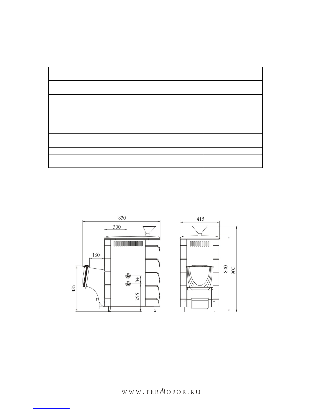
Specifications are presented in Table 1. Overall sizes of stove are presented in figures 1-3. Installation
dimensions of the stove (aperture under fuel channel) are presented in clause 8.6.
There are following acceptable fuel types: fuel wood, peat briquette, woodchip briquette for enclosed-
type heaters.
Recommended volume of hot-water tank of a samovar type «Baykal»is 55-72 l. Recommended
volume of outboard hot-water tank is 63 l.
Heat time of a vapor room from 20C till 100C is approximately 60 min subject to correct thermal
protection.
ATTENTION! Hot-water tanks and heat exchange unit of samovar type «Kostakan»
aren’t included into delivery set.
6
The capacity of built-in heat exchange unit (for the model with the heat exchange unit) equals to 0.65l.
The size of the connecting thread of heat exchange unit fitting equals to G3/4. Mounting dimensions are
presented in figure 2.
Table1. Specifications of the stove with stones section «Angara 2012» and «Angara 2012 Vitra».
Model
Angara 2012
Angara 2012 Vitra
Calculated capacity size for space heating, CBM
8-18
Width, mm
415
500
Depth, mm (total)
830
850
Depth, mm (without including length of a fuel
channel)
595
595
Height, mm
900
900
Mass, kg
58
65
Capacity size of stones section, l
42
42
Mass of loaded stones, kg
70
70
Capacity size of combustor, l
40
40
Maximum capacity of fuel load, l
30
30
Maximum length of a log, mm
500
500
Diameter of attachable a flue, mm
115
115
Minimal height of a flue from fire-bar, m
5
5
ATTENTION! Maximum capacity size for space heating is determined by terms of
providing with effective convection heat transfer and standards of overall thermal
resistance of walling by SNIP (СНиП) (construction norms and rules) 23-02-2003.
Figure1. Overall sizes of the stove «Angara 2012»

7
Figure2. Overall sizes of the stove «Angara 2012 Vitra».
Figure3. Overall sizes of the stove «Angara 2012» with a short fuel channel.

8
6. STOVE STRUCTURE AND OPERATION
«Angara 2012» stove designed for operation in the intense combustion mode while temperature
increasing in the sauna room, and in the economy combustion mode to maintain the selected temperature.
The stove overall look and the main elements layout are shown in Figure 4.
«Angara 2012» stoves's firebox and stones section (1) made of heat-resistant high-alloy steel with a
chromium content not less than 13% with the wall thickness of 3 mm.
«Angara 2012» stove design scheme provides effective heat exchange. The stove stones section
consists of two components: an external open section (1), divided into two parts and internal closed one (7).
A special funnel provided for water supplying into the inner section (6).
External stones section (1), divided into two parts, provides the best use of heated stones mass and
temperature stability in the steam room. The large mass of stones laid into the internal section is a powerful
steam generator.
The internal stones section round shape protects against soot accumulation on the firebox walls.
Convector casing (2) covering the stove heating surfaces accelerates air heating in the steam room
forming a strong convection flow. Besides of that, it shades hard infrared radiation emitted from the hot
firebox walls, which creates soft warmth in the steam room and serves to protect against accidental contact
with the stove during its operation.
Through the special duct (8) secondary air is supplied into the stove flue ducts for exhaust gases post-
combustion and the stones section effective heating.
Outside-mounted fuel channel allows the stove firing in an adjacent room. Model with a short fuel
channel is for those who prefer to fire the stove inside the steam room.
Firebox door, rotating hinged opens at an angle required for a comfortable and safety fuel loading.
«Angara 2012 Vitra» model door manufactured in two interchangeable versions: the steel door (11)
with an outer panel self-cooling property and the door of the original design with translucent screen made
of heat-resistant glass SchottRobax ® (12).
«Angara 2012 Vitra» model completed with a panoramic fuel channel (4) and the door with
translucent screen made of heat-resistant glass SchottRobax ® with diagonal of 17cm (3). There is a gap in
the upper part of the door for pyrolysis self-cleaning of the translucent screen from soot settling.
Heat-resistant glass screen allows you to monitor combustion process and simply enjoy living fire.
The fire-bar (9) made of solid cast iron installed in the lower part of the firebox. The ash box with
sliding ash drawer (10) is under the firebox.
With the stove operation, primary air required for combustion is supplied through the ajar ash drawer
(4) and bar (9) to the fuel. The bar provides combustion process acceleration and a powerful high-
temperature flame at the ignition moment. It provides a uniform wood burning which is so necessary for a
bathhouse stove.
Ash falls into the ash box through the gaps of the bar and you can easily clean the stove without
combustion process interrupting.
Combustion gases are directed into the chimney through the flue pipe with diameter of 115 mm.
In the model with a heat exchanger the exchanger mounted within the firebox on the sidewall, there
are symmetrical openings closed with plugs on the firebox opposite wall. The heat exchanger provides
water heating in the outside tank and its location inside the firebox accelerates heating process greatly.
The stove components without large thermal load are made of structural steel.

9
The stove outer surface is covered with a heat-resistant organosilicon enamel of KO-868 type
ATTENTION! The manufacture reserves the right to introduce changes into the sauna
stove design not impairing its consumer properties.
«Angara 2012 Vitra»
«Angara 2012»
1. External stones section
2. Convector casing
3. Door with translucent screen made of heat-
resistant glass SchottRobax ® with diagonal of
17cm
4. Panoramic fuel channel
5. Chimney (chimney flue. It is outside the scope
of supply)
6. Special funnel for water supplying into the
inner section
7. Internal closed stones section
8. Fire box
9. Cast iron stove bar
10. Ash box with sliding ash drawer
11. Steel door
12. Door with translucent screen
Figure 4. layout of the main elements of the stove ―Angara 2012‖. Modification with heat exchange unit.

10
7. MARKING AND PACKING OF THE STOVE
7.1. Marking
On a stove there is an information code plate with details about a model of a stove, its mass, factory
serial number, production date of a stove and other technical features, and also the information on
certificates for this model.
7.2. Packing
A stove is packed in a transport pack. Maintenance manual in a packaging bag and components are
enclosed in the stove combustor.
On a pack of a stove at the front part there is a label with information about a model of a stove, its
mass, design features and production date.
7.3 Procedure of remove the packaging by a consumer
1. Cut a packing tape
2. Remove cardboard boxes
3. Remove a polyethylene
4. Pull from a stove maintenance manual and components (if available) and take off a packing
5. Take away blocks and turn off fixing bolts
6. Remove advertising stickers from a surface of a protective film.
8. SUITABLE APPLICATION
8.1. Operational constraints
ATTENTION! Don’t use the stove for industrial premises of categories A (А), B (Б), V (В)
of fire and explosion safety in accordance with NPB (НПБ) 105-95 (classification of
premises and buildings of fire and explosion safety).
ATTENTION! Don’t use matters as fuel which aren’t mentioned under point 5.
ATTENTION! Expressly prohibited using charcoal and coal briquettes as fuel.
ATTENTION! Don’t use alcohol-containing means, benzene, kerosene and other highly
inflammable matters for ignition. Don’t use a glossy paper, trimmings of wood particle
boards, laminated flooring board, orgalite because these matters would evolve noxious
substances under burning, and would be cause of outburst and damage of a stove.
ATTENTION! Don’t use the stove with an empty heat exchange unit and a hot-water tank
or an unconnected system of water heating (if available).
ATTENTION! Don’t use the stove inappropriately.
ATTENTION! Don’t use the stove in autohouses, trailers and tents.
ATTENTION! Don’t commit overheating of the stove at the time of its operation.

11
Overheating of the stove can be identified by red glow of the metal in the dark.
This situation can appear upon the uncontrolled air supply into the fire box. For example, when the
door is open. The stove warming up may lead to dangerous conditions of the stove operation and its
premature breakdown.
8.2. Commissioning of the stove
ATTENTION! At the time of the first heating of the stove applied on the metal industrial
oils and light volatile compounds of organosilicone enamel evolve smoke and smell,
which aren’t evolved in the following.
People having chest troubles and owners of the pets susceptible to smoke (for example birds) should
take precaution measures.
The first heating of the stove it is necessary making open-air with fire prevention discipline, at least
one hour, with charging of a fire box in half in the regime of active combustion.
For correct operation of the stove, at the time of the first heating it is necessary to organize a
temporary flue with height at least 2m.
For the model of stove with built-in heat exchange unit it is necessary to organize temporary water
heating system during the first pre-heating.
ATTENTION! Don’t make mechanical action to a surface of a stove till complete cooling
and final polymerization of paint at the time of the first heating in order to avoid damage
of a lacquer coating.
ATTENTION! The first heating of the model «Vitra» shall be carried out with opened
door of combustor to prevent smoked translucent screen.
Please, make sure in normal functioning of the all components of the stove and protective
constructions. A faulty stove is not permitted to operation.
An efficient stove:
Doesn’t have external damages of a carcass.
A door freely revolves on hinges, closely adjoins to a carcass and is efficiently fixed by a lock.
A translucent screen on a door (if available) doesn’t have damages.
Fire bar is safe without burnouts and cracks.
An ash drawer has to freely move and it closely adjoins to a carcass in the closed position.
A heat exchange unit (if available) doesn’t have any damages.
8.3. Stones for stones section
It is necessary to load special stones into stones section. The manufacturer recommends using
gabbrodiabase, peridotite, talcum peach, jadeite. These volcanic rocks possess a beautiful pattern and
composed of durable minerals against physical and chemical action. Also, these volcanic rocks don’t
contain harmful impurities. These volcanic rocks possess considerable heating capacity, stand against large,
repeated temperature differential. Also, stones are fireproof and don’t break. Irregular shape of stones and
difference of its sizes provide maximum filling of stones section and maximal area of heat output.
ATTENTION! Stones of unknown origin can contain, numerously, harmful sulfides and
radionuclides, which make its useless and even dangerous for using in a sauna.

12
Stones shall be rinsed by scrub brush in flowing water before load.
Do not put stones higher than a top level of the stove, because stones will not heat-up to temperature
needed for quality steam formation.
Attention! Exclude the possibility of excessive water supply to the non-burning hot stones.
In this case the intensive stones section walls oxidation process will take place due to the
direct contact of water and metal. This reduces the service time of the stones section and
as the result of its burning-through.
Attention! Hot steam exhaust from the stones section takes place when water is supplied
to the non-burning hot stones. Supply water carefully.
During the long use of the stove it is necessary to carry out the shift of stones not less than once per
year. At the same time the pebble gravel should be removed and destroyed stones should be replaced with
the new ones.
8.4. Preparation of premises to installation of the stove
Protect from fire constructions of premises:
•Walls (or partition) of inflammable materials have to be protected with plaster with
thickness 25 mm on an expanded metal or a metal plate on an asbestos paper with thickness
10 mm, from a floor to a level of 250 mm above the top of the stove.
•A wall (or partition), through which fuel channel pass, shall be from nonflammable materials
from a floor to a level of 250 mm above the top of the stove. Recommended thickness of a
wall is 125 mm.
•A floor under the stove has to be protected by a foundation from brick at least two coating or
other nonflammable material at a distance of 380 mm from a wall of the stove.
•A floor of inflammable and combustible with difficulty materials in front of a door of a
combustor has to be protected with a metal plate with size 700×500 mm with length its side
along the stove.
•Make a fireproof partition in a passage of a flue through a ceiling.
•At the time of installation of a flue in premises with a roof of inflammable materials a flue
has to be protected with a spark arrester of gauze with an opening with size no more 5×5
mm, also have to block with nonflammable roofing materials a space around a chimney.
ATTENTION! A place of installation the stove and chimney will be done in accordance
with SNIP (СНиП) (construction norms and rules) 41-01-2003 or, in accordance with
technical standards of a country, where the stove would be exploited.
8.5. Air change in a steam room
It is recommended to organize a balanced system of ventilation for provision of good air change (see
figure 6).
A hole for fresh air intake (9) with a section about 100 square centimeters is made in a floor as closely
as possible to the stove or under the stove.
A hole for used air exhaust (6) is made in a wall just below of a level of a ceiling as far as possible
from the stove. For more moist and cold air exhaust, a vertical box (8) is installed to a top hole. A vertical
box possesses a vent hole at a distance not more than 50 cm from a floor.

13
It is recommended to install adjustable latches (7) in air inlet and exhaust outlet for possibility to
control air exchange.
ATTENTION! It is necessary to provide constant inflow of fresh air into the room where
the stove is operating. The breach of the condition may lead to unstable operation of the
stove and appearance of dangerous situations such as poisoning with carbon monoxide,
fire breaking-out.
8.6. Stove assembly
ATTENTION! All the stove assembly and stones setting into the stones section works shall
be carried out only after total cooling off of the stove.
ATTENTION! The stove is heavy. Make sure that you have the possibilities and equipment
for its moving.
ATTENTION! It is prohibited to install the stove in the places where the stove will create
obstacles for people moving during evacuation.
ATTENTION! It is necessary to carry out the installation of smoke sensors and gas
detectors in the rooms where the stove is installed.
Mount the stove to the specially prepared place. Make sure that the stove is assembled and installed
correctly.
Provided after reading this manual you still have any doubts concerning the stove correct installation
you should consult the stove assembly specialist who is aware of all the aspects of safe and correct
installation of stoves.
A scheme of installation of the stove is presented in figure 6. Distance from the door of the combustor
till the wall opposite will be at least 1250 mm. Distance between the top of the stove and an unguarded
ceiling will be at least 1200 mm.
Distance between an external surface of the stove, flue and wall will be at least 500 mm, for
constructions of inflammable materials will be 380 mm, for constructions of inflammable and combustible
with difficulty materials which are protected by a metal plate on an asbestos paper with thickness 10 mm or
with plaster on expanded metal with thickness 25 mm.
Do not install the stove into the niche in a wall or into the fire place.
Distance from the side of a fuel channel till a wall shall be at least 30 mm. If thickness of a wall is 125
mm then a door of a combustor will have the most correct position.
Wall opening for fuel channel from the level of support feet shall have the following dimensions
(height × width):
for «Angara 2012 2011» models —480×270 mm.
for «Angara 2012 2011 Vitra»models —545×410 mm.

14
For installation of the model «Vitra» on the site of
operation it is necessary:
1. Unscrew self-tappers 8 ps. that fixes a door with a
frame to a fuel channel and remove a door; (see
Figure 5)
2. Install the stove on the site of operation (edge of a
fuel channel shall emerge from another side of a
baffle);
3. Install back a door with a frame. I will be fixed by
self-tappers.
Figure 5. Door disassembling under
installation of the stove «Vitra»
a metal plate on a heat-insulation
material (an asbestos paper with
thickness 10 mm)
wood (inflammable material)
a thermal insulation of a
nonflammable material
(haydite/dross/ basalt wool)
bricks and so on (a nonflammable
material)
a material of foundation
(nonflammable)
1. A sheet in front of a combustor
2. A flue cover
3. Flue with a thermal insulation of
type «sandwich construction»
4. An overlap of a nonflammable
material for a roof
5. A roof splicing
6. A hole for used air exhaust
7. Adjustable latches
8. A vertical box
9. A hole for fresh air intake
10. Start-sandwich
Figure 6. Installation of the stove in
inflammable material premise
15
For the models «Angara 2012», the stove is installed on the site and then a door put on a fuel channel.
A door is included in a delivery set.
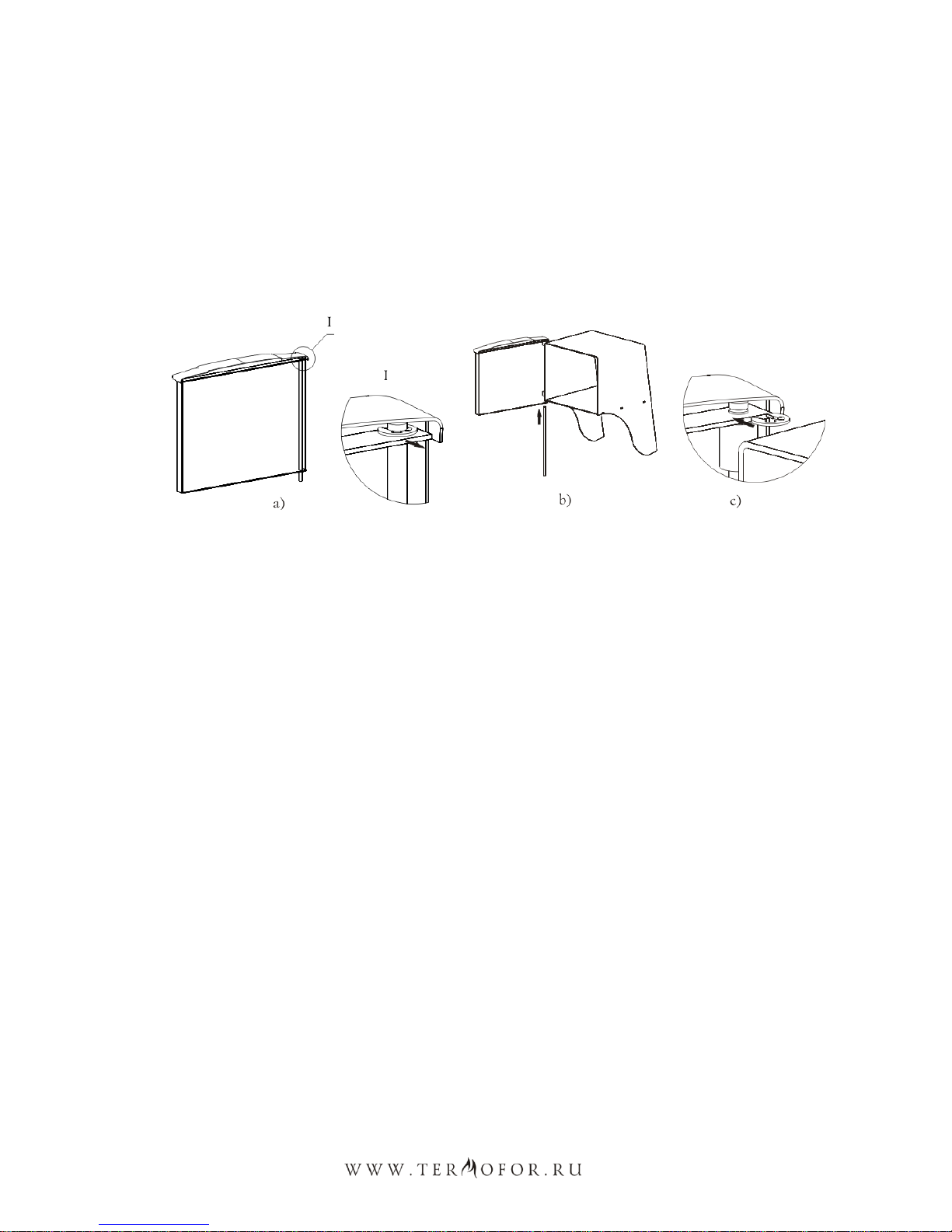
Installation of a door on the models «Angara 2012»:
1. Remove a stop quick-detachable collar, then remove the axis out of the door, see figure 7 a;
2. Install the door on sleeves of a fuel channel and unite holes;
3. Set an axis from bottom to top through holes. Place a groove under a collar in the top part of an
axis, see figure 7.b;
4. Install a stop quick-detachable collar in a groove on an axis, see figure 7.c.
Figure 7. Assembly of the door under installation of the stove «Angara 2012».
The stones shall be set into the stones section after the end of the stove mounting and its connection to
all the necessary systems.
8.7. Stove pipe assembly
During the use of the stove, the stove pipe shall be treated very carefully.
Stove pipe (chimney stack) –is the means of air ventilation of exhausted gases, it provides the draught
that facilitates the constant air intake into the heating equipment necessary for normal burning process. The
stove is designed only for operation with natural draught.
The stove shall have its own stove pipe.
ATTENTION! It is prohibited to connect the stove to any air ducts except for the cases
when the air duct is designed only for operation as the stove pipe.
ATTENTION! It is prohibited to connect the stove to the stove pipe that is connected to
another equipment or heating unit.
ATTENTION! The stove does not draw. The draught is made only with the stove pipe.
The stove pipe has two functions for the stove trouble-free operation. The first –is the piping of
exhaust gases generating during the fuel combustion. The second –is draught for air intake into the fire
chamber for combustion maintenance.
Draught –is the natural air or gases movement through the stove pipe. It generates due to the feature
of warm air to go upwards.

16
As far as the warm air moves in the stove pipe the low pressure is generated in the place of the stove
connection to the stove pipe. The greater pressure from the outside of the stove makes the air move into the
area of lower pressure –into the area of fire box. Thus the air intake into the fire chamber happens. This
constant air inflow is the draught.
The stove won’t be operating effectively if there is no draught of the definite value.
The optimal draught for operation of stoves of «Termofor» trademark equals to 12±2 Pa.
Provided the excessive draught the considerable air flow will be entering the fire chamber and this will
lead to the stove overheating. Fire hazard may appear.
With the insufficient draught the insufficient amount of air for fuel proper and complete combustion
will be entering the fire chamber and this may lead to smoke generation in the room. The creosote
generation increases upon the formation of excessive smoke in the stove pipe and that may ignite creating
the fire hazard in a house.
Creosote —is colourless (sometimes yellowish or yellow-green), inflammable, hardly soluble in
water oily liquid with strong smell and pungent taste extracted from wood and coal tar. This is the mixture
of phenols mainly guaiacol and cresols. Soluble in alcohol and ether. Poisonous.
Creosote will inevitably be generated in your stove and stove pipe. To reduce the speed of its
generating it is necessary to:
Use only dried billets that were dried during the period for not less than one year.
Use hardwood of broadleaf woods that is more compact (more heavy) and combust with the higher
temperature.
Before the use of the stove check and amend all that can influence the draught. Reducing or increasing
of draught may influence the draught by set of different factors, some of them may change in the course of
time. Factors influencing the draught:
Atmospheric pressure –may act from outside of a room, from inside and from both side by turns.
Weather conditions to which the high pressure conforms (clear and cold days) usually create the perfect
conditions for combustion.
Negative pressure outside the heated room –is created with the help of ventilation facilities such as:
ventilation inside the sauna room, draft hood, equipment for clothes drying, boilers with forced draught.
Upon the negative pressure the air flow in the stove pipe will go backwards at that ―negative draught‖ or
―backdraught‖ is created.
Negative pressure can be neutralized by opening the door or window in the room with the stove.
The stove pipe temperature –the draught in the warmed up stove pipe is better than in the cold one.
The cold stove pipe quickly cools off hot gases going upwards and this will prevent their further going
upwards. Combustion of the first fuel charge will be enough for the stove pipe warming.
Stone stove pipes and stove pipes with section larger than the heating device are warmed up for a
considerably longer period of time.
The chimney stack shall have minimal number of elbows. The straight pipe is preferable. The use of
more than two piping may lead to the draught loss and possible smoke generation.
The manufacturer recommends to use modular thin-walled chimney stacks made of high-alloy,
corrosion-resisting steel of «Termofor» trademark with the diameter of 115 mm. They are effective, durable
and required thee minimum expenses for assembling and during operating.
For reliable fastening of the units together it is necessary to use «collar-strainer»; the use of self-
drilling screws is allowed if necessary.

17
In case of installation of thick-walled metal, ceramic, asbestos-cement or other chimney stack of
greater weight it is necessary to unload the stove from its weight.
ATTENTION! The manufacturer shall not be responsible for the influence of external
factors on the reduction of natural draught in the stove pipe.
ATTENTION! It is prohibited to use chimney stacks with galvanic coating.
ATTENTION! Do not use pipes from different manufacturers in the stove pipe.
ATTENTION! To avoid the smoke blowing into the heated room all the places of chimney
stack units connection against each other and the stove it is necessary to compact with
high-temperature sealant (not less than 1000°С) providing the air-tightness of the pipe
junctions.
ATTENTION! The junction of stove pipe units in overlaps and fire block is prohibited.
ATTENTION! The section of chimney stack located in the zone of sub-zero temperatures
shall be obligatory heat insulated by non-combustible material, withstanding
temperatures not less than +400 °С.
The ideal solution for chimney stack –is the installation of ready-made pipe units with heat insulation
of ―sandwich‖ type of «Termofor» trademark.
In case of connection of the stove to fixed built-in stove pipe or in other cases it is not recommended
to deflect the axis of chimney stack from the vertical line for more than 45°.
ATTENTION! sauna stove and chimney stack assembly shall be carried out by qualified
workers from the specialized construction and installation company in compliance with
the requirements of SNIP 41-01-2003 (construction norms and rules) or in compliance
with technical norms of the country where the stove will be used.
ATTENTION! It is strictly prohibited to make dismountable the connections of the stove
with the stove pipe or other structural elements of the room.
ATTENTION! In case of fire in the stove pipe shut the dampers of air supply into the fire
chamber, leave the room and immediately call the firemen.
In case of fire in the stove pipe it is necessary to have a clear scheme of actions that shall be elaborated
by consulting the specialist. After the fire in the stove pipe will die down, the stove pipe shall be cleaned
and checked for the destructions. Make sure that there are no flammables around the stove pipe.
8.8. Stoves with heat exchange unit
Stoves with heat exchange unit help to locate the tank for hot water outside the steam room and install
it in wash room. «Termofor» heat exchange units are produced in two variants:
1) heat exchange unit of «samovar» type installed at the outlet nozzle of the stove pipe (do not
supplied as part of package);
2) built-in heat exchange unit, installed at the wall of fire chamber inside the stove (supplied with the
stove of corresponding model);

18
For the first variant water in the heat exchange unit is heated due to hot gases piped into chimney
stack. Such heat exchange unit can be moved by its connecting pipe in any direction.
For the second variant –water heating is carried out due to the direct contact of heat exchange unit
walls with the flame in the fire chamber.
Built-in heat exchange unit with factory assembly is installed from right (or left) side of the stove. If
necessary it can be shifted to another side of the stove –this will allow to install the hot water tank from the
side convenient to the Consumer.
Heat exchange units are made of heat-resisting high-alloy stainless steel with the content of chromium
not less than 13%.
«Termofor» company recommends along with «Angara 2012» sauna stove use the heat exchange unit
«Kostakan» of «samovar» type of «Termofor» trademark.
8.9. Shift of built-in heat exchange unit
Holes in fire chamber and convector walls (in models with heat exchange unit) for the connecting
pipes output are on the both sides of the stove that is why the heat exchange unit can be shifted if necessary
to another side.
It is recommended to carry out the shift of built-in heat exchange unit before the stove assembly.
Provided the stove has been already installed and is in use then it is necessary to carry out its disassembling.
ATTENTION! All works shall be carried out when the stove is fully cooled off.
For heat exchange unit shift to another side it is necessary (convector and heat exchange unit fastening
for all models of «Angara 2012» sauna stove are analogous):
1. Remove the convector frame by unscrewing 4 self-drilling screws (figure 8);
2. Remove the convector by unscrewing 5 self-drilling screws (figure 9);
3. Remove the heat exchange unit (figure 10) by unscrewing 2 nuts and taking it off the holes, the
gaskets shall stay on the nipples;
4. Remove 2 blind plugs by unscrewing nuts and taking off the blind plugs from the holes;
5. Insert the heat exchange unit into the holes on the other side of the stove and fasten it with nuts;
6. The rest holes shall be fastened with blind plugs;
7. Carry out the convector assembly in the reverse order (see cl. 2-1).
Figure 8. Disassembling of «Angara
2012» sauna stove convector frame
Figure 9. «Angara 2012» sauna stove convector
disassembling

19
ATTENTION! During the heat exchange unit shift the gaskets made of non-combustible
material shall be located from the inner side of the fire chamber.
Figure 10. «Angara 2012» sauna stove heat exchange unit and blind plugs disassembling
8.10. Installation of a water heating system
ATTENTION! Don’t connect a heating system to a heat exchange unit.
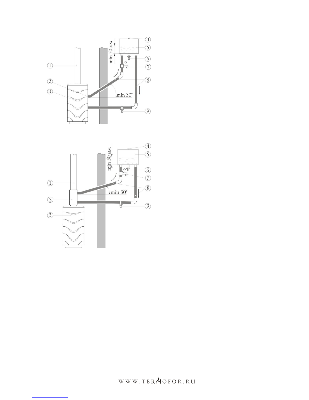
A general scheme of installation of a water heating system is presented in figure 11 –with a fixed heat
exchange unit; 12 –with heat exchange unit of «samovar» type. Elements of a water heating system
including a heat exchange unit aren’t supplied as part of delivery set.
A water heating system consists of:
•A heat exchange unit (2) with two fitting adapter;
•Connective pipes (pipeline) (8);
•An outboard tank (5) for hot water with two fitting adapters for connecting to a heat transfer
system and one fitting adapter for installation of a tap of hot water distribution;
•A tap for hot water (6), a threeway tap (7) and a tap for water drain from a system (9).
At the time of installation of a water heating system, a bottom of an outboard tank for hot water shall
be over of a level of a top fitting adapter of a heat transfer device no less than 30 cm.
ATTENTION! At the time of pipelines installation, don’t permit its sagging in horizontal
segments. It is recommended to install these pipelines at an angle of up no less than 30°.
ATTENTION! Don’t use pipes with work temperature of operation less than +95°C for a
water heating system.
20
1. Chimney
2. Fixed heat exchange unit
3. Stove «Angara 2012»
4. Connection with atmosphere
5. Outboard tank for hot water
6. Tap for hot water
7. threeway tap
8. Connective pipes
9. Tap for water drain
Figure 11. Scheme of installation of a water
heating system with using the fixed heat exchange
unit
1. Chimney
2. Heat exchange unit «Kostakan» of
«samovar» type
3. Stove «Angara 2012»
4. Connection with atmosphere
5. Outboard tank for hot water
6. Tap for hot water
7. Connective pipes
8. Connective pipes
Figure 12. Scheme of installation of a water
heating system with using the heat exchange unit
«Kostakan» of «samovar» type
ATTENTION! Don’t use connecting elements of a pipe fitting with nominal width less
than nominal width of fitting adapter of a heat exchange unit.
ATTENTION! It is prohibited to exceed the operating pressure in the water heating
system for more than 0.05 MPA (0,5 kgs/cm²) during the use of «Angara 2012»bath stove
with the heat exchange unit.
ATTENTION! Pressure test of the system by higher pressure shall be carried out when the
heat exchange unit is switched off.
ATTENTION! Only clear water shall be filled to a water heating system. It shall meet
requirements of quality in the context of salt, iron, lime content and other.
If necessary to get hot water at a short time then it will be permitted to make water distribution before
its entry to a tank. For this purpose, it is necessary to connect a threeway tap (7) to a pipe of hot line
This manual suits for next models
1
Table of contents
Popular Stove manuals by other brands


Golden Eagle
Golden Eagle WOOD PELLET STOVE Operating & installation manual

Anvil
Anvil STA0001 R02 Installation operation and care

Elite Products
Elite Products EDB-302F instruction manual

Stuv
Stuv 16/58-cube Installation, user and servicing instructions

Artel
Artel NCA115-2A manual

United States Stove Company
United States Stove Company KP5522 manual


