TERMOTECHNIKA Ecomat 15 User manual
TERMOTECHNIKA
OPERATION AND MAINTENANCE MANUAL
FOR PELLET BURNERS ECOMAT

TERMOTECHNIKA MICHAŁ KOTELBA Address: Postępu 190 A, Zgorzała, 05-500 Piaseczno
Office address: Marynarska 14 lok.310, 02-674 Warszawa; NIP (tax ID): 716-230-90-85 REGON (statistical no.): 060301812 E b
i u r o @ s u p e r g r z a n i e . p l M + 4 8 –601-086-243 M + 4 8 6 0 6 1 6 7 4 6 7
www.ecomat.waw.pl
1
Table of contents
1. Safety of use ............................................................................................................................... 3
1.1. Commentary ........................................................................................................................... 3
1.2. Hints and tips for fitters and users .......................................................................................... 3
1.3. Conditions for safe operation .................................................................................................. 3
2. General information .................................................................................................................... 4
2.1. Adjusting boiler and burner heating power to central heating and usable warm water heating
purposes ................................................................................................................................ 4
2.2. Burner structure and its elements ........................................................................................... 5
2.3. Recommended fuel and fuel storage ...................................................................................... 6
2.4. Short technical description and sequence of the burner’s functions ........................................ 6
2.5. Auxiliary equipment for burner and boiler ............................................................................... 7
3. Technical specification .............................................................................................................. 9
3.1. Technical parameters of the burners ...................................................................................... 9
3.2. Burner and feeder dimensions and conditions for installation within the boiler ...................... 10
3.3. Burner presets ....................................................................................................................... 16
3.4. Electric connection ................................................................................................................. 16
3.5. Assembling, launching and adjusting the burner ................................................................... 17
4. Maintenance .............................................................................................................................. 19
4.1. Cleaning - setting burner cleaning mechanism - examples ................................................... 19
4.2. Replacing the ignition device ................................................................................................ 20
4.3. Causes of faulty operation and fault removal ........................................................................ 22
4.4. Burner disposal .................................................................................................................... 23
5. Declaration of conformity for the ECOMAT burners .............................................................. 25
6. Assembly report ....................................................................................................................... 26
7. Warranty card ........................................................................................................................... 27
Schedule 1 –Approximate heat demand of buildings ............................................................... 29
Schedule 2 - Boiler temperature adjuster operation manual ..................................................... 30

2
.
1. Safety of use.
1.1. Commentary
This operation and maintenance manual includes important information about correct
assembly and operation of the Ecomat burner which is designed to be used with a
boiler. This manual is primary intended for fitters who possess necessary knowledge
and experience in operation and maintenance of heating systems. The first launch of
the burner shall be done by a duly trained professional. Improper launch or assembly
of the burner results in warranty loss.
1.2. Hints and tips for fitters and users
Assembly and operation should be done according to local norms and standards
concerning:
- appropriate positioning of the boiler, manner of combustion air supply and
flue gas discharge;
- technical and safety equipment for water heating systems.
1.3. Conditions for safe operation
Burner and boiler shall be operated in properly fitted rooms only. Since boiler with the
pellet burner uses combustion air from the room (the boiler-house) which it is
positioned in, thus insufficient air intake may cause flue gas emission and a threat of
carbon monoxide presence. Hence, it is forbidden to downsize or close the inlet and
outlet holes.
The size of an inlet hole which supplies combustion air should be at least the
same as the cross-section of the boiler’s chimney. In order to illustrate
importance of the above, it is worth mentioning that e.g. the Ecomat 25 burner
that operates at full capacity of 25 kW burning about 5.5kg of pellet per hour
requires approx. 100m3 of combustion air.
If such an irregularity occurs, it should be immediately corrected. Otherwise, further
operation of the boiler must be discontinued and the fitter has to inform the user in
writing about such a situation.

As far asthe chimney isconcerned, it is crucial to secure an appropriate flue draught.
Chimney height shall be as follows:
3
- from at least 2m at a diameter of 100mm or more to maximum chimney height of about
8-9 meters which corresponds to the flue draught of less than 25Pa.
Chimneys of flue draught exceeding 25Pa should be equipped with a flue draught


6
limiter. The Ecomat burner can be assembled within a boiler which water heating
system is secured by an expansion vessel or within a boiler which includes a cooling
coil with a water valve.
Boiler with the burner assembled should be operated only by adults who are familiar
with operation manuals of both the boiler and the burner. Children are not allowed to
stay in the vicinity of the operating boiler without supervision of adults. Ash produced
during combustion should be removed into a non-combustible container with a lid.
2. General information.
2.1. Adjusting boiler and burner heating power to central heating and usable
warm water heating purposes.
In order to select the right burner for a boiler, it is necessary to determine the boiler
heating capacity. Generally, the burner should not have a greater heating capacitythan
the boiler. Otherwise, when the boiler has a greater heating capacity than the burner,
the condensation of flue gases may occur and boiler corrosion can be intensified.
Therefore, it is a matter of principle that the Ecomat burner is connected to the boiler
of the same heating capacity or a capacity within a tolerance of 10%.
Approximate boiler heating capacity can be selected on the basis of a parameter which
refers to the cubic space of the rooms being heated. The parameter depends on the
building thermal insulation degree. In case of very good insulation degree, the heating
capacity of 40 W/m3 should be assumed. In case of building with poorer thermal
insulation degree, the coefficient should amount to about 60 W/m3. Another way
consists in calculating heat demand of a building as a total capacity of individual
heaters. In this case the heat demand should be increased by 20% in order to avoid
operating burner and boiler at maximum heating capacities.
Boiler heating capacities calculated for various cubic spaces of buildings, wall
insulation levels and types of applied fitting are listed in the schedule 1 to this manual.
2.2. Burner structure and its elements

7
The Ecomat 15, Ecomat 25, Ecomat 40, Ecomat 70 burners, which burn tiny wood
briquettes (pellets), are optimal devices designed to work with heating boilers of
heating capacity 4-15 kW, 6-25 kW, 12-45 kW and 20-65 kW respectively. Burners can
be installed into most solid fuel boilers and some oil-fired boilers, provided that the
combustion chamber of the boiler allows ash aggregation and its periodical removal.
The Ecomat pellet burners cannot be installed into boilers with water-cooled grate. In
order to install the burner in a solid fuel boiler with a cast iron grate, it is necessary to
remove the grate allowing ash to fall from the burner into the ash pit. The burner
mounted above a water-cooled grate will not operate correctly because such a grate
constitutes an obstacle that disables free movement of ash into the ash pit. TheEcomat
burners have been designed in such a way to provide automatic operation. Thanks to
a movable grate and a special skimmer, the burner head cleans automatically. The
Ecomat burners are environmental-friendly and economic devices - they are
characterized by low flue gas emission and low electric energy consumption (less than
40W in average).
Efficiency level of burners mounted within a boiler amounts to about 98%. When the
burner is mounted within the boiler, the whole burner head is positioned in the boiler
and the external surface of the burner does not excessively warm up during operation.
Operation of the burner proceeds automatically, beginning from ignition, through
burning and ending with cooling and cleaning the burner head off residues of ash and
sinter, and then switching into the stand-by mode.
The Ecomat burners are composed of the following units:
1. the burner with a burner head and a movable grate mounted within its body as well
as other elements and wiring covered with a metal housing;
2. an external conveyor system of 1.5m in length (standard);
3. electric control box with electronic burner adjuster;
4. flexible plastic feeding pipe which supplies fuel and connects the feeder with the
burner.

8
2.3. Recommended fuel (pellet) parameters:
- diameter ø 6 (for all burners) or 8 mm ( above Ecomat 25);
- maximum length: 4-5 times the pellet diameter;
- content of fine fractions i.e. fractions of 3mm and less (sawdust and ashes): not
more than 1%;
- calorific value above 16 MJ/kg or 4.7 kW/kg;
- dust content: not more than 2%;
- moisture content: less than 10%;
- pellet must not contain any loose inclusions, such as: bark, wood chips etc.
There are no special requirements for pellet storage. However, the storage place
should be roofed over and kept free of excessive moisture as pellets easily absorb
moisture and crumble. It is not recommended to store larger volumes of pellet for
longer periods of time. It should be used up within a single heating season.
2.4. Short technical description of operation of a boiler equipped with a pellet
burner.
Heating boilers with the Ecomat pellet burners operate automatically. The most
important controlling unit is the controller which controls the heat source i.e. the pellet
burner, fuel feeder and the central heating and usable warm water pumps.
The adjuster’s display shows information about current status of the automatic
operation. When the boiler and the burner do not operate, the status is displayed as
“stand-by” provided that the burner has been completely switched off (“STOP” status).
The “stand-by” status means that the adjuster awaits for a signal to launch central
heating or usable warm water heating. Heating begins when the room thermostat is
launched and it ends when temperature inside the house reaches required level.
Thus, it should be obligatory to install the room thermostat. On the other hand, usable
water is being heated within hours set on a separate timer (recommended auxiliary
equipment).
When central heating and usable warm water heating is conducted at the same
time, the user can select heating priority for the usable water on the adjuster or

9
continue heating both the house and the water. In the latter case, time needed to heat
water to desired temperature will be appropriately longer.
In order to heat usable water only (e.g. during summer season), it is enough to
switch the adjuster into the “summer” mode (central heating system is switched off,
then).
When the burner and the boiler finish heating the house to desired temperature
and finish heating usable water to desired temperature, the burner duty cycle
concludes and the device switches into “stand-by” mode.
This solution allows saving considerable amounts of fuel because thermal energy
is produced only when the central heating system demands it.
In each duty cycle, the Ecomat burners automatically ignite and then they operate
at maximum power, modulated power or minimum power accordingly with varying
demand for heat. Once the tasks for both central heating system and usable water
heating system are accomplished, fuel feeding is stopped, the burner burns residues
of fuel that remain on the grate and it automatically cleans off the ash - according to
preset duty cycle. Hence, the device operates automatically.
The user is only required to replenish fuel in the fuel hopper, remove ash from the
boiler’s ash pit and periodically clean the boiler.
2.5. Auxiliary equipment for burners and boilers.
- room thermostat;
Room thermostat is an auxiliary equipment for the burners. Typically, the thermostat
is installed during the last stages of assembling the burner within the boiler. By
default, the burner is sold with a jumper (bridge) for GH connectors in the lowvoltage
terminal block of the burner adjuster. During assembly, the bridge needs to be
removed and the COM-NO clean contact of a room thermostat should be plugged.
- usable warm water module;
Usable warm water module is another optional equipment for the burners. It works
with all types of room thermostats that allow weekly settings and it enables the user
to set times which the usable warm water is to be prepared in. Except for the set
times, heating of usable water is electronically disabled which allows saving fuel. The

10
goal of the two auxiliary parts of equipment (i.e. room thermostat and usable warm
water heating module) is to allow the central and usable warm water heating systems
operate at the same time. It helps to save fuel and ensures optimal operation of the
burner-boiler unit.
- emergency stop;
The last item of auxiliary equipment for the Ecomat 15, Ecomat 25 and Ecomat 40
burners is the so-called emergency stop, i.e. a limit switch which is mounted onto
the door of a boiler which the burner was installed in. The limit switch has to be
installed in such a way to ensure that the emergency stop function is launched when
the door is opened (i.e. the burner stops operation).
Therefore, the burner can only operate when boiler’s door remain closed. It is a kind
of fire protection system which prevents from starting the burner when the door is
open. It is also helpful at removing ash from the boiler because it protects against
launching the burner accidentally during that operation. Suggested solution is
illustrated in the image below:

11
By default, the burner is equipped with a bridge installed over the X-connector (E-F).
Limit switch for the emergency stop should be plugged after removing the bridge
installed over the connector.
3 . Technical specification.
3.1. Technical parameters of the
burners.
- nominal heat output for Ecomat 15 : 4-15 kW;
- nominal heat output for Ecomat 25 : 7-25 kW;
- nominal heat output for Ecomat 40 : 12-40 kW
- nominal heat output for Ecomat 70 : 20-65 kW;
- heating efficiency: 94%;
- Ecomat 15 weight: 11 kg
- Ecomat 25 weight: 11.5 kg
- Ecomat 40 weight: 15.5 kg
- Ecomat 70 weight: 25 kg
- standard feeder: length 1.5m;
- fuel: pellets ø 6 mm or ø 8 mm;
- supply voltage: 230 VAC 50 Hz;
- average power consumption: about 40 W;
- degree of protection: IP 40.

12
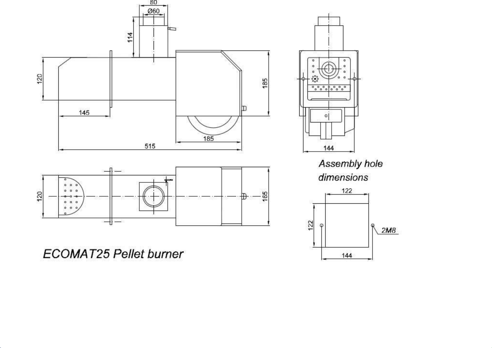
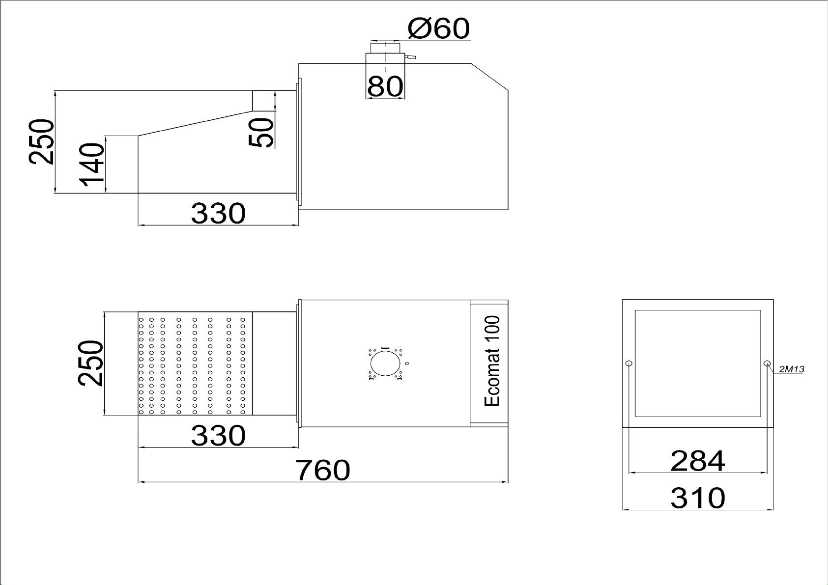
3.2. Burner and feeder dimensions and conditions for installation in the boiler

13
14

15

16
17
Assembly hole
dimensions
ECOMAT100 Pellet burner

18
Fuel feeder diagram for ECOMAT 15 and ECOMAT 25
Fuel feeder diagram for ECOMAT 40
Fuel feeder diagram for ECOMAT 70

19
Conditions for installation within the boiler.
The Ecomat burners have been designed in such a way that the flame burning
direction in unobstructed space is at an angle of about 45 degrees. It allowed
custom installation of the burner within boilers which have a narrow and at the same
time a tall combustion chamber (as in the case of upper combustion boilers) as well
as in the boilers with a lengthier and at the same time a low combustion chamber
(as in the case of lower combustion boilers or oil-fired boilers).
Irrespectively of the above, the boiler combustion chamber for Ecomat 15 and
Ecomat 25 should be characterized of the following minimum dimensions: -
minimum depth: 300 mm;
- minimum space over burner combustion pipe: 100 mm (taking into account the above
minimum depth);
- minimum width of the combustion chamber: 250mm;
The boiler combustion chamber for Ecomat 40 should be characterized of the following
minimum dimensions: - minimum depth: 500 mm;
- minimum space over burner combustion pipe: 200 mm (taking into account the above
minimum depth);
- minimum width of the combustion chamber: 400mm;
The boiler combustion chamber for Ecomat 70 should be characterized of the following
minimum dimensions: - minimum depth: 600 mm;
- minimum space over burner combustion pipe: 300 mm (taking into account the above
minimum depth);
- minimum width of the combustion chamber: 500mm;
When the burner is assembled (e.g. within the lower boiler door), the inside
of its combustion chamber should allow ash to fall freely from the burner, favourably
into an ash drawer made of metal. Minimum distance between the bottom of the

20
burner and the bottom of the ash pit should not be lesser than 100mm - the larger
is this distance, the less often it is necessary to remove ash.
3.3. Burner pre-sets.
The burner pre-sets adjusted by the manufacturer are as follows:
- power is set to the nominal value, i.e. 15 kW, 25 kW, 40 kW and 70 kW respectively.
Modification of power parameters needs to be done by a fitter (authorized serviceman).
The user can adjust (change) power to his/her boiler by way of selecting 60% to 100%
power level through settings available in the user’s menu. - all parameters have been
adjusted to the following types of fuel: type 1 –pellet ø 6 mm of average quality with
up to 1% of ash content. In case of other type of pellet (e.g. ø 8 mm or a pellet of lower
quality), it is possible to select and set parameters for fuels labelled as type 2, 3 and 4.
This should be done by an authorized serviceman.
- burner cleaning parameters are appropriate for a pellet of average ash content, i.e.
1% - “automatic” mode and the burner is cleaned after each work cycle. It is possible
to change cleaning mode when a pellet of increased ash content is used. In such cases
it is recommended to set the “combo” cleaning mode, i.e. the mode including cyclic
cleaning during regular operation of the burner as well as the final cleaning conducted
after the work cycle ends. This should be done by an authorized serviceman.
- by default, the burner is set to central heating as well as usable warm water heating
mode of work. However, if the burner should only heat the central heating system, then
the usablewarm water circuit needs to be switched off (set the usable warm water circuit
parameter into “off” mode).
3.4 Electric connection.
Make the electrical connection in accordance with the burner manufacturer's operating
instructions.
3.5 Assembling, launching and adjusting the burner
This manual suits for next models
3
Table of contents
Popular Burner manuals by other brands

Ecoflam
Ecoflam MINOR 20.1 manual

Riello
Riello 20045452 Installation, use and maintenance instructions

Outdoor Gourmet
Outdoor Gourmet TF2002501-OG-00 Assembly instruction

Carlin
Carlin 201GAS instruction manual

Riello Burners
Riello Burners BF3 installation manual

Heatmaster
Heatmaster DG-SS-18 installation instructions


Town & Country Fireplaces
Town & Country Fireplaces TC36.NG04C instructions
 Installation & owner's manual")
EarthCore
EarthCore ISF-SBVT24VE(N,P) Installation & owner's manual

Riello
Riello G20KI instruction manual

Riello
Riello DB9 LSE C13 TC FS1 A0 Installation, use and maintenance instructions

baltur
baltur TBL 85P Instruction

Midco
Midco Incinomite J83-DS Installation and service instructions