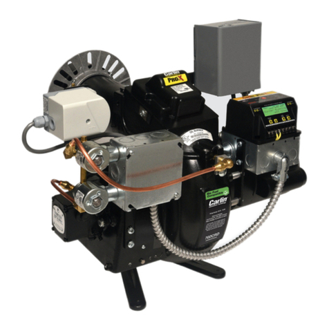
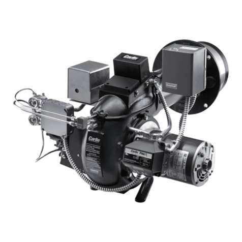
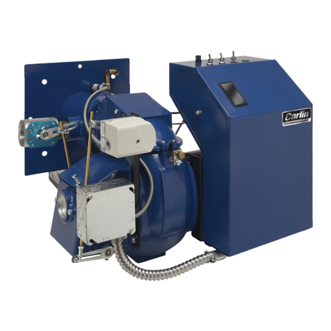
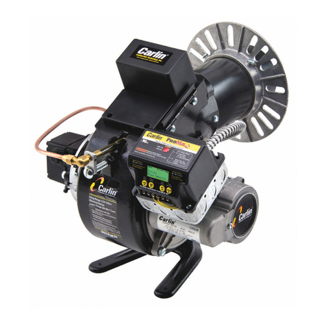
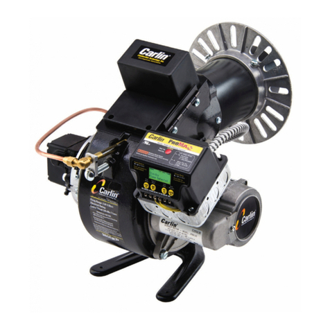
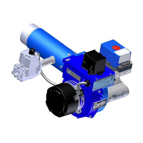
Carlin 201GAS User manual

Contents
PLEASE read this rst.......................................................... 2
Codes and standards........................................................... 2
201GAS burner at-a-glance................................................ 3
Prepare site • prepare burner • mount burner.............. 4
Install gas piping.................................................................. 9
Wire burner......................................................................... 10
Check system • start-up burner/appliance.................. 11
Perform checkout procedures • ll out certicate..... 13
Maintenance and service procedures........................... 16
Troubleshooting ................................................................. 17
Dimensions and mounting information........................... 19
Replacement parts............................................................. 20
Instruction manual
Ratings
Input: .................................................150,000 to 399,000 Btuh
Fuels: .........................................Natural gas or propane gas
Max. supply pressure..........................14 inches w.c.
Min. supply pressure.............................5 inches w.c.
Manifold pressure...............................3.5 inches w.c.
Electrical: Power...........................................120V/60 Hz/1-Phase
Motor.....................................1/6 or 1/4 HP, 3450 RPM
Current...................................Approx. 2.5 or 4.4 amps
Ignition: ........................Carlin Model 41800 solid state ignitor
Control: ........ Carlin Model 60200FR microprocessor control
Agencies: ..........................................................................UL Listed
Installer/servicer — Except where specifically
stated otherwise, this manual must be used only by a quali-
fied service technician. (In the state of Massachusetts, this
product must be installed by a licensed Plumber or Gas Fitter.)
Failure to comply with this or other requirements in this manual
could result in severe personal injury, death or substantial
property damage.
User — Refer only to User’s Information booklet for
information regarding operation of this burner. The burner
Instruction Manual is intended only for your service techni-
cian. The burner and heat exchanger must be inspected and
started at least annually by your service technician.
™
70 Maple Street East Longmeadow, MA 01028
Ph 413-525-7700 Fx 413-525-8306
Carlin Combustion Technology, Inc.
Tech support 800-989-2275 carlincombustion.com
©Copyright 2011 — Carlin Combustion Technology, Inc.

Model 201GAS burner — Instruction manual
Carlin part number MN201GAS Rev. 03/14/11
– 2 –
Where appliance instructions differ from this manual, follow the appliance instructions.
PLEASE read this first . . .
Special attention flags
Please pay particular attention to the following when you see them through-
out this manual.
Notifies you of hazards that WILL cause severe personal
injury, death or substantial property damage.
Notifies you of hazards that CAN cause severe personal injury,
death or substantial property damage.
Notifies you of hazards that WILL or CAN cause minor per-
sonal injury or property damage.
Notifies you of special instructions on installation, operation or
maintenance that are important, but are not normally related
to injury or property damage hazards.
Follow the guidelines below to avoid potential severe
personal injury, death or substantial property damage.
Installer/service technician . . .
• Readallinstructionsbeforeproceeding.Performallprocedures,
and in the order given to avoid potential of severe personal injury,
death or substantial property damage.
• Beforeleavingthesiteafterstart-uporservice,reviewtheUser’s
information manual with the user. Make the user aware of all
potential hazards and perform the training outlined below.
Train the user . . .
• Toproperlyoperatetheburner/applianceperthismanualandthe
appliance instructions and the User’s information manual.
• Tokeepthismanualatorneartheburner/applianceforreadyac-
cess by the user and service technician.
• Tocontacttheservicetechnician,gassupplierorredepartment
should the user smell gas.
• Tokeeptheappliancespacefree of flammable liquids or vapors
and other combustible materials.
• Donotuselaundryproducts,paints,varnishesorotherchemicals
intheroomoccupiedbytheburner/appliance.
• Tocontacttheservicetechnicianatleastannuallyforstart-upand
burner/applianceservice.
When servicing the burner . . .
• Disconnect electrical supply to burner before attempting to
service to avoid electrical shock or possible injury from moving
parts.
• Burnerandappliancecomponentscan beextremelyhot.Allow
all parts to cool before attempting to handle or service to avoid
potential of severe burns.
General information
Burner applications
Follow all instructions in this manual and the appliance manual. Where ap-
pliance instructions differ from this manual, follow the appliance instructions.
Read the label attached to the burner air tube to verify the burner is correct
for the appliance being used. See page 7 for procedures.
Damage or shortage claims
The consignee of the shipment must file damage or shortage claims im-
mediately against the transportation company.
When calling or writing about the burner . . .
Please provide us with the UL serial number and burner model number to
assist us in locating information. Enter this information on the Installation
Certificate in this manual. The certificate information can be helpful when
troubleshooting or obtaining replacement parts.
Fill out burner adjustment label
Fill out the burner adjustment label, located on the housing above the rating
label after completing installation and burner setup.
Should overheating occur: (1) shut off the manual gas control
to the appliance, (2) do not shut off the control switch to the
pump or blower.
Codes and standards
Theinstaller/servicerissolelyresponsibleforcompliancewith
all applicable codes and standards.
Burner listings
Carlin 201GAS burners are tested and approved under standards ANSI
Z21.17-latest edition and CSA 2.7-M86.
Codes
Burner/applianceinstallationsmustcomplywithallapplicablelocalcodes
and,whereapplicable,withtheInstallationofDomesticGasConversionBurn-
ers,ANSIZ21.8,theNationalFuelGasCode,ANSIZ223.1/NFPA54-latest
edition,andtheNationalElectricalcode,ANSI/NFPA70-latesteditionforU.
S.installationsorB149.1/B149.2InstallationCode,andCSAC22.1/CSA
C22.2 Canadian Electrical Code for Canadian installations.

Model 201GAS burner — Instruction manual
Carlin part number MN201GAS Rev. 03/14/11 – 3 –
Where appliance instructions differ from this manual, follow the appliance instructions.
201GAS burner at-a-glance
1 Air tube (ange omitted for clarity), with powder coat paint nish
2 Diffuser plate (hole or slot pattern)
3 Gas manifold (concentric cylinders swaged and welded at ends) —
Gas manifold delivers gas to gas openings on inner wall of manifold
near the diffuser plate.
4 Ignitor electrode insulator
5 Flame rod insulator
6 Ignitor electrode
7 Flame rod electrode
8
Gas orice nipple — see pages 7 and 8 for orice sizing requirements
9 Hinged cover plate (for access to blower wheel & electrodes)
10 Ignitor (Carlin Model 41800 solid state electronic ignitor — 9,000 volts,
continuous duty rated)
11 Primary control — Carlin Model 60200FR microprocessor-based inter-
rupted ignition ame supervisory control (ame rectication)
12 Flame current test jack
OFF
ON
201003
2345 6 78 9 10 11
13
12
14
15
16
17
18
19
21
23
1
20
22
13 Burner junction box
14 Motor (with permanently-lubricated bearings and thermal overload
protection)
15 Blower housing (cast aluminum), with powder coat paint nish
16 Blower wheel
17 Air band — Only a single adjustment required for setting combustion
air; see page 7 for starting setting based on input
18 Airow proving switch — Prevents burner from ring if air is not moving
19 Airow proving switch sensing line (aluminum) — blower inlet
20 Airow proving switch sensing line (aluminum) — blower outlet
21 Combination gas valve (with integral gas pressure regulation — set
for 3½” w.c. outlet pressure)
22 Gas supply entrance — ¾” NPT; 5” w.c. min; 14” w.c. max
23 Flame rod/ignition electrode assembly yoke

Model 201GAS burner — Instruction manual
Carlin part number MN201GAS Rev. 03/14/11
– 4 –
Where appliance instructions differ from this manual, follow the appliance instructions.
1. Prepare site • prepare burner • mount burner
Prepare installation site
Inspect, repair and/or replace vent system
Donotinstallthisburnerunlessyouhaveveriedtheentire
vent system and the appliance are in good condition and
comply with all applicable codes. And . . .
The vent and chimney must be sized and constructed in
accordancewiththeNationalFuelGasCode,NFPA54/ANSI
Z223.1,orB149.1/B149.2InstallationCodeforCanadian
installations. Appliances equipped with a gas conversion
burner are treated as fan-assisted appliances.
The vent system must not be pressurized unless the vent
piping and vent system are designed accordingly. The vent
must provide draft at all times (negative pressure in vent).
Donotinstalloruseanexistingmanualdamperinthevent
connector or vent.
Donotconnecttheapplianceventconnectortoachimney
or vent serving a fireplace, incinerator or solid-fuel-burning
apparatus.
In a cold climate, do not vent into a masonry chimney that
has one or more sides exposed to the outside. Install a listed
stainless steel liner to vent the flue products.
A defective vent system could result in severe personal injury,
death or substantial property damage.
Vent/chimney sizing
• Followalllocalcodeswhensizingtheventandchimney.
• Refer to the appliance manufacturer’s manual, when available, for
venting recommendations.
Prepare vent/chimney
• Secureallmetalventjointswithscrews,followingtheventmanufacturer’s
instructions. Seal all joints in the vent system and chimney. Repair masonry
chimney lining and repair all mortar joints as needed.
• Wheredraftuctuationsarelikely,installadouble-actingbarometricdraft
regulator in the vent piping. (The damper must be located in the same
space as the appliance.) Install a manual reset spill switch in the top of
the draft regulator outlet. Wire the switch into the appliance limit circuit to
shutofftheappliance/burnerifsustaineddowndraftshouldoccur.Refer
totheappliancemanufacturer’sinstructionmanualforrecommendations
regarding the need for a barometric draft regulator.
• Providesupportfortheventpiping.Donotresttheweightofanyofthe
vent piping on the appliance flue outlet.
Figure 1 Vent and vent connector installation

Model 201GAS burner — Instruction manual
Carlin part number MN201GAS Rev. 03/14/11 – 5 –
Where appliance instructions differ from this manual, follow the appliance instructions.
1. Prepare site • prepare burner • mount burner (continued)
Prepare installation site
Verify combustion/ventilation air openings (Figure 2)
Installingtheburner/applianceinaspacethatdoesnotprovide
enough air for combustion and ventilation can result in severe
personal injury, death or substantial property damage. Follow
all applicable codes and guidelines below to ensure space
has sufficient air openings.
Large spaces
For appliances located in basements, ventilated crawl spaces or other large areas, no
additional air openings should be necessary. Exception: If the building construction
isunusuallytight(seeNationalFuelGasCode,NFPA54/ANSIZ223.1,orB149.1/
B149.2InstallationCodeforCanadianinstallationsfordenition),youwillneedto
provide air openings into the building if appliance air comes from inside. Provide
one opening within 12 inches of the ceiling, and one opening within 12 inches of
the floor. Size each opening to provide free area (after deduction for louvers) of 1
squareinchper1,000Btuhinputofallfuel-burningappliancesinthebuilding
.
Confined spaces — air from inside building
If air openings connect to areas inside the building, provide two openings,
one within 12 inches of the ceiling, the other within 12 inches of the floor.
Each opening must have a free area (after deduction for louvers) of 1 square
inchper1,000Btuhofallappliancesinthespace.Ifthebuildingconstruction
isunusuallytight(seeNationalFuelGasCode,NFPA54/ANSIZ223.1,or
B149.1/B149.2InstallationCodeforCanadianinstallationsfordenition),
you will need to provide air openings into the building. Provide two openings
sized and located as for the openings into the boiler space.
Confined spaces — air from outside
If air openings connect directly to outside, provide two openings, one within
12 inches of the ceiling, the other within 12 inches of the floor. Each opening
must have a free area (after louver deduction) of:
• Ifdirectlythroughsidewall:1squareinchforeach4,000Btuhofall
appliances in the space.
• Ifthroughverticalducts:1squareinchforeach4,000Btuhofallap-
pliances in the space.
• Ifthroughhorizontalducts:1squareinchforeach2,000Btuhofall
appliances in the space.
Optional air inlet boot
For spaces not fitted with large enough air openings, you may be able to
apply the optional Inlet air boot, with air ducted directly to the air boot from
outside.Youmustuseaventoutlet/airinletterminationapprovedbythe
appliance manufacturer. Refer to the appliance instructions and Inlet air
boot instructions for correct application.
You will also have to apply this option if the appliance space may contain corrosive
contaminants, such as laundry products, paints, varnishes or other chemicals.
Even when using the optional Inlet air boot, make sure the
space provides enough ventilation to prevent overheating of
the appliance, burner and controls. If there is risk of over-
heating, you must install ventilation air openings sized large
enough to provide air for cooling the equipment. Failure to
provide ventilation can result in severe personal injury, death
or substantial property damage.
Figure 2 Locating & sizing air openings

Model 201GAS burner — Instruction manual
Carlin part number MN201GAS Rev. 03/14/11
– 6 –
Where appliance instructions differ from this manual, follow the appliance instructions.
Verify clearances
• Verifythattheburner/appliancewillmaintainallclearancestocombus-
tiblewallsoroorandallclearancesrequiredforservice/maintenanceas
required in the appliance manual and applicable codes.
Prepare the appliance
Burner input: Install a gas burner sized for the normal input
ratingoftheappliance.Donotinstallaburnerwithahigher
ringratethantheappliancerating.Donotinstallaburner
with a firing rate more than 10% lower than the appliance
rating. The appliance and vent system could be damaged
due to condensation.
Clean the appliance: Clean the appliance thoroughly and
seal all joints. Test all electrical components and verify the
relief valve works (boilers only).
Verify combustion chamber dimensions comply with the
minimum dimensions shown in Figure 3, page 7. Install or re-
place chamber liner if required by the appliance manufacturer.
The burner must not extend into the combustion chamber.The
end of the burner air tube must be within ¼” of the inside
face of the chamber. If the space around the burner air tube
is more than ¼”, wrap the burner air tube with minimum
2300 °F – rated ceramic fiber blanket to seal off the gap.
Repair or replace damaged appliance components.
Inspect the appliance thoroughly. Follow appliance manufac-
turer’sguidelinesforrepairorreplacementofanycomponent
found defective.
When cleaning the appliance or working with ceramic fiber refrac-
tories or fiberglass insulation, see WARNING on this page.
Failure to comply with the above could result in severe per-
sonal injury, death or substantial property damage.
Prepare appliance for burner mounting
The universal flange supplied with 201GAS burners is
intended only for firing chambers with negative overfire pres-
sure. For pressurized firing, you must obtain a burner with a
welded flange, designed for use with the appliance. You can
also use the optional forced draft flange. Failure to comply
could result in severe personal injury, death or substantial
property damage.
Seepage19forrequireddimensionsandboltlocations.
1. Prepare site • prepare burner • mount burner (continued)
Prepare installation site
Verify combustion/ventilation air openings (continued)
When sizing air openings for combustion and ventilation,
include air required for exhaust fans and other appliances,
such as clothes driers, that require air for operation.
Check appliance manual and applicable codes for required sizing of com-
bustion and ventilation air openings.
• Verifythatopeningsareunobstructed.
• Verifythatappliancespaceandairsourcespacesarefreeof:
– Gasoline or other flammable liquids or vapors.
– Combustible materials.
– Air contaminants, such as laundry products, paint, thinner, varnish,
etc.
• Conrmwithuserthattheareawillbekeptfreeofthesematerialsatall
times.
Ceramic ber or
Fiberglass insulation
Ceramic fiber materials, such as chamber liners, may
contain carcinogenic particles (chrystobalites) after
exposure to heat. Airborne particles from fiberglass or
ceramic fiber components have been listed as poten-
tially carcinogenic by the State of California. Take the
following precautions when removing, replacing and
handling these items.
Avoid breathing dust and avoid contact with skin or
eyes. Wear long-sleeved, loose-fitting clothing, gloves
andeyeprotection.UseaNIOSHN95certiedrespira-
tor. This respirator meets requirements for protection
from chrystobalites. Actual job requirements or NIOSH
regulations may require other or additional protection.
Forinformation,refertotheNIOSHwebsite,http://www.
cdc.gov/niosh/homepage.html.
Ceramic fiber removal:To prevent airborne dust, thor-
oughly wet ceramic fiber with water before handling.
Place ceramic fiber materials in a plastic bag and seal
to dispose.
Avoid blowing, tearing,sawing or spraying fiberglass
or ceramic fiber materials. If such operations are neces-
sary, wear extra protection to prevent breathing dust.
Wash work clothes separately from other laundry.
Rinse clothes washer thoroughly afterwards to prevent
contamination of other clothing.
NIOSH First aid procedures:
Eye exposure — irrigate immediately
Breathing—freshair.
Model 201GAS burner — Instruction manual
Carlin part number MN201GAS Rev. 03/14/11 – 7 –
Where appliance instructions differ from this manual, follow the appliance instructions.
1. Prepare site • prepare burner • mount burner (continued)
Prepare burner and components
Donotinstalloroperatetheburnerifanycomponentisdamaged
or if burner does not comply with the specifications of Table 1
and other guidelines in this manual.
Air tube insertion length (UTL)
• Usableairtubelength(UTL)isthedistancefrommountingangetoend
ofairtube.Verifythattheendoftheairtubewillbeushwith,ornomore
than ¼ inch short of, the inside of the appliance combustion chamber
front wall when the burner is mounted. See Figure 3 and Table 1 below,
for further information.
Diffuser plate
• Verifycorrectdiffuserplate(item2,page3).Comparediffuserplatelisted
on air tube label with diffuser plate listed in Table 1.
Figure 3 Combustion chamber dimensions (see Table 1)
Gas orifice drill size
• Thegasoriceisdrilledthroughaplateintheendoftheoricenipple
(seeitem8,page3).Readthefactory-drilledoricesizeonthelabel
attachedtotheburnerairtube(seeitem1,page3)neartheblower
housingend.Ifthegasoricesizeisnotcorrectforyourapplication,
orifthelabelisillegibleforanyreason,checktheoricesizedirectly
andredrilloriceorreplaceifnecesary,asfollows(nextpage).
Table 1 Burner specifications for 201GAS burners
Input
Note 1
Burner orifice
drill size
Approximate
air band setting
Notes 1 & 2
Diffuser Minimum chamber dimensions
Inches (Notes 3, 4, 5)
(VC = min. diam. of vertical cylinder chamber)
UTL
Air tube
insertion length
Btuh Natural
gas
Propane
gas
%Slots Air
shutter
C/L L1 L2 W H VC
150,000 9/32 7/32 15 2Yes C 4 11 14 810 9½ Burners with welded flange have fixed
usable tube length (UTL). Verify length
is correct for the application. Burners
with adjustable flange: Usable tube
length (UTL) varies with air tube length:
175,000 5/16 1/4 30 2Yes C 4 12 16 810 10
200,000 11/32 9/32 60 2Yes C4½ 14 17 811 12
225,000 11/32 9/32 8 2No B4½ 15 18 911 13 Nominal
air tube
length
----------
8”
10”
12”
14”
16”
UTL
min.
---------
1 ¾”
1 ¾”
1 ¾”
1 ¾”
1 ¾”
UTL
max.
---------
2 ½”
4 ½”
6 ½”
8 ½”
10 ½”
250,000 3/8 5/16 25 2No B4½ 16 19 911 14
275,000 13/32 5/16 40 2No B4½ 17 21 10 11 15
300,000 13/32 5/16 15 4No A 5 17 21 12 12 15
350,000 15/32 11/32 35 4No A5½ 17 21 12 12 15
399,000 9/16 7/16 80 4No A 6 20 24 14 13 17
Note 1 High altitude applications: The maximum burner input at sea level is 399,000 Btuh. Reduce this capacity by 4% per 1,000 feet above sea level. Example — max.
capacity at 5,000 feet is 319,000 Btuh (20% reduction).
Pressurized firing: Maximum burner input decreases with increasing overfire pressure. Assume a reduction in maximum burner input of approximately 5% at 0.1
inches w.c. and 10% at 0.2 inches w.c. You will have to increase the air band opening to compensate for the increased pressure. Follow the procedures given in
this manual to check combustion with instruments to determine the correct air band setting. Do not fire into a chamber with pressure higher than 0.2 inches w.c.
and never fire at a higher pressure than recommended by the appliance manufacturer.
Note 2 Use this as the starting setting only. Adjust air band setting, if necessary, after performing combustion testing (see page 13).
Note 3 Some tested appliances may operate satisfactorily with dimensions less than the above.
Note 4 Horizontal cylindrical chambers — diameter must be no less than column “W” above
Horizontal stainless steel cylindrical chambers — diameter at least 1 to 4 inches larger than column “W” above.
Note 5 A corbel may help heat transfer in a larger boiler or furnace, provided it is recommended by the appliance manufacturer.

Model 201GAS burner — Instruction manual
Carlin part number MN201GAS Rev. 03/14/11
– 8 –
Where appliance instructions differ from this manual, follow the appliance instructions.
Mount burner in appliance
• Verifyapplianceburnerfrontplatedimensionsperpage19.
• Slidegasketsuppliedwithburneroverendofairtube.
• Insertburnerintoapplianceopeningandboltinplace.
Inspect components and wiring
• Visuallyinspectallburnercomponentsandwiring.
• Verifythatwiringisintactandleadsaresecurelyconnected.
• Verifythatallburnercomponentsareingoodcondition.
Install gas valve on burner
1. ReadWARNING’sonpage9beforeinstallinggasvalve.
2. Apply a small amount of pipe dope (suitable for propane gas) to gas valve
outlet connection and to threads of gas line union and nipple. Assemble
pipe nipple to gas valve and one half of union.Assemble other half of union
to burner gas connection nipple. Join the union.
To avoid damage to gas valve, do not hold valve with a pipe
wrench or overtighten. Use only a crescent wrench or other
means. Failure to comply could result in severe personal injury,
death or substantial property damage.
3. Feed wires into air pressure switch housing and secure conduit fitting with
lock nut.
4. Connectwhitewirefromvalvetowhitewirefromburnerwithwirenut.
Attach black wire quick-connect terminal to switch terminal connector
(violet wire from burner is attached to other switch terminal).
Figure 6 Flame rod/ignitor electrode assembly
1. Prepare site • prepare burner • mount burner (continued)
Figure 5 Flame rod and ignitor electrode placement
Inspect/redrill gas orifice when required
• Turnoffpowertotheburner/appliancebeforeproceeding.
• Closemainmanualgasvalveingaslinetoburner.Thendisconnectthe
ground joint union to allow rotating burner combination gas valve.
You must disconnect power to burner and close main manual
gas valve before proceeding. Failure to do so could result in
severe personal injury, death or substantial property dam-
age.
• Removewirejunctionboxcoverongasvalvebyremovingthesingle
screw attaching the box to the valve body. Then pull the two insulated
spade connectors off of the gas valve terminals.
• Removethecombinationgasvalve(item21,page3)andtheorice
nipple (item 8, page 3). Remove the orifice nipple from the gas valve.
• Readthecorrect oricedrillsizefromTable1,page7.Thencheck
actual orifice size using that size twist drill bit.
• If gas orifice is smaller than required, redrill the orifice to the correct
size, if necessary.
• If gas orifice is larger than required, obtain a replacement orifice
nipple from Carlin. If necessary, drill the orifice hole in the replacement
orifice nipple to the correct size.
Drilltheoricecarefully,avoidingdrillwobble.Wobblewill
cause the orifice to be over-sized. The orifice nipple should
be secured in a vise, if possible, to ensure it is steady during
the drilling process.
• Writetheoricesizeontheoricenipplelabel.
• Replacethegasvalveandpiping,usingonlypipedopelistedforuse
with liquefied petroleum gases. Make sure the arrow on the orifice
nipple label points in the direction of gas flow.
Flame rod and ignitor electrode
• Inspecttheburnerfromairtubeend.Flamerodshouldextendthrough
thediffuserplateasshowninFigure5.Ignitorelectrodeshouldbeush
with inner face of diffuser plate as shown.

Model 201GAS burner — Instruction manual
Carlin part number MN201GAS Rev. 03/14/11 – 9 –
Where appliance instructions differ from this manual, follow the appliance instructions.
2. Install gas piping from meter to combination gas valve
Code compliance
Theburner/applianceinstallationmustcomplywithcodeslistedonpage2and
any other locally applicable codes.
Piping from meter to burner
Connect from the gas supply to the burner combination gas
valve inlet using new, clean black iron pipe and malleable iron
ttingsonly.Donotusecopper,brass,castironorgalvanized
pipe or fittings.
Providesupportforgaspiping.Donotrestweightofpiping
on burner gas valve.
Apply pipe dope sparingly at all joints. Use only pipe dope listed
forusewithpropanegas.Donotusepipesealingtape.
Donotholdgasvalvewithpipewrench.Usecrescentwrench
orothersmooth-jaweddevice.Donotovertighten.
Failure to comply with above could result in severe personal
injury, death or substantial property damage.
1. If possible, install a new gas line directly from the gas meter. If you
are using an existing gas line, verify it is clean and in good condition,
and verify it is large enough to handle the load of all connected appli-
ances.
2. When branching from a common gas line, do not tap off from the bottom
of horizontal sections — only from the side or top.
3. Install a main manual shutoff valve, sediment trap and ground joint union
near the burner combination gas valve connection as shown in Figure 7.
4. Iftheburnerisinstalledinsideanappliancejacket,installthemainmanual
gas valve and sediment trap external to the jacket.
5. Sizepiping(orverifysize)usingTable2.Youwillndadditionalinformation
ongaslinesizingintheNationalFuelGasCode,NFPA54/ANSIZ223.1,
orB149.1/B149.2InstallationCodeforCanadianinstallations.
Gas supply pressure — natural or propane
• Maximumsupplypressure: 14 inches w.c.
• Minimumsupplypressure: 5 inches w.c.
Donotexposethecombinationgasvalvetogaspressurein
excessof14incheswatercolumn.Higherpressurecoulddam-
age the valve seat, resulting in potentially hazardous condition.
When pressure testing piping at higher pressures, disconnect
burner from gas line before testing.
Ifthegassupplypressurecanexceed14incheswatercolumnat
any time, you must install a lockup type gas pressure regulator
in the gas supply piping, ahead of the main manual gas valve
installed at the burner.
Test and purge gas line
Read WARNING above.
Pressure test and purge the line. Pressure testing should be done by the gas
supplier or utility, following all applicable codes.
Table 2 Capacities of black iron pipe, cubic feet gas/hour
1 Pipe to meter or branch
2 Main manual gas shutoff valve
3
Use clean, burr-free black iron
pipe and malleable iron ttings
4 Ground joint union
5 Sediment leg
Figure 7 Connecting gas supply piping to burner
6 Burner combination gas valve
7 Upstream pressure tap, 1/8”
8 Outlet pressure tap, 1/8”
9 Gas regulator access screw
10 Gas valve wire junction box
In the state of Massachusetts, when lever-type gas shutoffs are
used, they must be T-handle type only.
Capacities in cubic feet per hour
for pipe carrying natural gas or propane
Pipe size
(inches)
Total length of gas piping,
from meter to burner connection (feet)
20 40 60 80 100
Natural gas @ .60 specic gravity, pressure drop 0.3 in. w.c.(note1)
½ 92 63 50 43 38
¾ 190 130 105 90 79
1 350 245 195 170 150
1¼ 730 500 400 350 305
Natural gas @ .60 specic gravity, pressure drop 0.5 in. w.c.(note1)
½ 120 82 66 57 50
¾ 250 170 138 118 103
1 465 320 260 220 195
1¼ 950 660 530 460 400
Propane gas @ 1.55 specic gravity, pressure drop 0.3 in. w.c.
½ 57 39 31 27 24
¾ 118 81 65 56 49
1 217 152 121 105 93
Propane gas @ 1.55 specic gravity, pressure drop 0.5 in. w.c.
½ 74 51 41 35 31
¾ 155 105 86 73 64
1 288 198 161 136 121
Note 1 For natural gas with specic gravity other than 0.60,
consult National Fuel Gas Code, NFPA 54/ANSI
Z223.1, or Canadian B149.1/B149.2 for correction
factor.

Model 201GAS burner — Instruction manual
Carlin part number MN201GAS Rev. 03/14/11
– 10 –
Where appliance instructions differ from this manual, follow the appliance instructions.
Code compliance
Theburner/applianceinstallationmustcomplywithcodeslistedonpage2and
any other locally applicable codes.
General wiring requirements
Read and follow the guidelines below. Failure to comply could
result in severe personal injury, death or substantial property
damage.
Electrical shock hazard—Disconnectelectricalsupplytothe
burner before attempting to service.
Electrically ground burner — The burner must be grounded
in accordance with local codes or, in the absence of local codes,
withtheNationalElectricalCode,ANSI/NFPA70(orCSAC22.1/
CSA C22.2 Canadian Electrical Code for Canadian installs.)
Label all wires before removing for servicing. Wiring errors
couldresultinunsafeappliance/burneroperation.
Readappliancemanufacturer’sinstructionscompletelybefore
wiring burner.
The 60200FR control requires a constant 120 vac power source
from the appliance as well as power from the appliance limit
circuit. See Figure 8. Check polarity carefully. If hot and neutral
wires are reversed at appliance power source, the control will
lockout on flame failure.
If replacing any of the wire supplied with the burner, use minimum
#18AWG125°Corbetter.
Verify power supply
1. The burner requires a 120 vac/60hz/single-phasepowersupply,with
at least a 10-amp fuse. The current draw will be (when equipped with
typicalmotorandCarlin41800electronicignitor)approximately:
2. The 120 vac powerconnectionstotheblackandred/whitewiresofthe
60200FR must be the same polarity from the same power source.DO
NOT attempt to supply separate power sources. Check the power from
theappliancewithavoltmeter.Verifythatthesupplytotheblackandred/
white wires are from the 120 vac HOT side and that the power is no less
than 102 vac nor more than 132 vac.
Checking burner flame signal
The60200FRusesamerecticationtodetecttheame.Becausethegrounded
metal surface area near the flame rod is much larger than the surface of the
flame rod, current flows through the flame more easily in one direction than
theother.ThiscausesanACvoltageappliedtotheamerodtoresultinaDC
current. (Note that, if the flame rod should touch a grounded metal part, the
currentwouldbeAC,notDC,andthecontrolwouldsenseamefailure.)
The 60200FR control has a 3 mm flame signal test jack (item 12, page 3) that
can be used with a flame signal meter, such as the Honeywell W136. Or you
can use a standard 3 mm stereo plug fitted with two leads. Connect these leads
inserieswithyourammeterleadstoreadDCmicroamps.
The minimum flame signal needed to satisfy the 60200FR sensing circuit is
0.8 microamps. The control will register flame failure at any lower signal.
Figure 8 Wiring diagram — 201GAS burner with 60200FR primary control
3. Wire burner

Model 201GAS burner — Instruction manual
Carlin part number MN201GAS Rev. 03/14/11 – 11 –
Where appliance instructions differ from this manual, follow the appliance instructions.
4. Check sytem • start-up burner/appliance
Inspect/check system
Beforestartingtheburnerandappliance,verifythesystemhasbeeninstalled
as directed by this manual and the appliance instructions.
Check gas piping for leaks
Disconnecttheburnerfromthegassupplylineifgasline
testpressurewillexceed14inchesw.c.Exposingtheburner
combinationgasvalvetopressurehigherthan14inchesw.c.
can damage the valve seat, resulting in potentially unsafe
operation.
You can usually test the gas piping by allowing the line to fill with gas to
main regulator outlet pressure.
1. Shut off gas flow to all equipment connected to the meter.
2. Iftestpressurewillbelessthan14inchesw.c.,turntheburnercom-
binationgasvalveknobtoOFF.Iftestpressurewillbehigherthan14
inches, remove the burner from the gas line by shutting off the main
manualgasvalveinstalledneartheburner(perFigure7,page9)and
disconnecting the ground joint union. See warning above.
3. Watch the gas meter dial. For a one half cubic foot per revolution dial,
thereshouldbenomovementofthedialforatleast5minutes.For
larger volumes per revolution, increase this time proportionately.
4. Ifyoudetectagasleak,locatetheleakwithasoapsudsmixtureand
repair it. Then test the system for leaks again.
Donottestforleakswithanopename.Anddonotuse
oxygen as a test gas. Either of these could cause an explo-
sion, resulting in severe personal injury, death or substantial
property damage.
Verify flame failure Lockout of 60200FR control
1. Install a hose barb fitting in the combination gas valve outlet pressure
tap and connect with a hose to a U-tube manometer.
2. Close the main manual gas valve and turn the combination gas valve
knob to ON.
3. Turn on power to appliance and set appliance limit(s) to call for heat.
4. Burnermotorwillstart.The60200FRwillrunforitsprepurgetiming,
then start the ignitor. Approximately one second later, the combination
gas valve will open. (The manometer should show almost no pressure,
because the main manual gas valve is closed.)
5. AftertheTrialforIgnitionPeriod,the60200FRwilllockoutandturnon
theredLED.Theignitorwillshutoffandthegasvalvewillclose.Turn
off power and set controls to stop call for heat.
6. If Lockout does not occur, replace the 60200FR control.
Inspect/check system
Beforestartingtheburnerandappliance,verifythesystemhasbeeninstalled
as directed by this manual and the appliance instructions.
Donotstarttheburnerifyousmellgasoriftheremaybegas
present in the appliance combustion chamber, appliance or
the vent system. An explosion could occur, causing severe
personal injury, death or substantial property damage.
During initial start-up, you must be constantly alert for
emergency conditions such as fuel leaks, electrical malfunc-
tions, etc. Familiarize yourself with the location of manual
shutoff valves and switches so you can quickly use them if
needed.
Iftheburnerfailstoignite,NEVERattempttomanuallybypass
the normal sequence of the control, which provides purging
of the combustion chamber.
Figure 9 Air band adjustment
Bleed gas line
Purgeallairfromthegasline.Purgetooutsideofthebuilding,NEVERinto
the appliance or burner.
Leak test near-burner gas piping
If piping near burner has not already been pressure tested, open main
manual gas valve on supply to burner and smell around area for any signs of
gas.Apply a soap suds mixture to all gas piping joints near burner and check
for any leaks. If any leaks appear, repair before proceeding and retest.
Set burner air band
SeeFigure9.Loosenairbandlockingscrew.Thenrotatebanduntilitisopen
to the setting given in Table 1, page 7. Tighten air band locking screw.
The Table 1 setting will probably be satisfactory without change. If the
combustion test indicates a need for more or less air, however, you will
have to adjust the band accordingly.
Check burner and primary control
Inspectburnerthoroughly.Verifythathingedcovergasketisclosedand
screwistight.Verifyallwiringisinplaceandallcomponentsaresecure
and in position.

Model 201GAS burner — Instruction manual
Carlin part number MN201GAS Rev. 03/14/11
– 12 –
Where appliance instructions differ from this manual, follow the appliance instructions.
Should overheating or an emergency occur, immediately:
•Shutoffmainmanualgasvalve.
•Shutoffcontrolswitchtoburner.
Under some circumstances power should remain on for
circulating blowers or other equipment. Determine proper
response before attempting start-up.
If burner fails ignition on several attempts, close gas valve
and use burner blower to purge appliance before restart.
Model 60200FR diagnostic LED’s
– Amber OFF –RedOFF – Green OFF
– Amber ON –RedON – Green ON
– Amber FLASHING –RedFLASHING
– Amber BLINKING (blinksoffmomentarilyevery3to4seconds)
Please see 60200FR control label for trial for ignition (TFI)
and purge timings.
Start-up & operation
Donot start theburner ifthe combustion chamber
containsresidualgas.Allowgastodisperse.
PerULrequirements,thecontrolwillnotturnonifthe
amerodsensesameduringtheself-test.Iftheame
rodsensesame,thegreenLEDturnson.Thecontrol
willremaininself-test mode untiltheamerod no
longersensesame.TheamberLEDwillremainon,
butblinkoffmomentarily every3to4seconds.
Run Theburnercontinuesringduringcallforheatifthe
amerodsensesame.AmberandredLED’sareoff
andgreenLEDisonduringnormalrunning.
Lockout IftheameroddoesnotsenseamewithintheTFI
timelimitaftergasvalveactivation,lockout occurs.
ThecontrolturnstheredLEDonconstant,andcloses
the alarm contact.GreenLEDisoff.
ToReset
Pushinandholdresetbuttonfor1second,thenrelease.
Latch-up Ifthecontrollocksout3 timesduringasinglecallfor
heat, latch-upoccurs.Thecontrolturnsonboththe
amberandredLED’sconstant.Youmustusethespecial
procedurebelowtoresetthecontrolafterlatch-up.
Reset from latch-up — Only a qualied service techni-
cian should attempt to reset the control after latch-up.
The problem that caused the repeated burner prob-
lems must be corrected before returning the burner
to normal operation.
Pushinandholdtheresetbuttonforabout10seconds.
TheredandamberLED’swillashalternately.
Afterthe LED’s begin ashing,continue to holdthe
resetbuttonforaboutanother20seconds.TheLED’s
willturnoff.Releasetheresetbuttonandthecontrol
willrestart.(ReleasingthebuttonbeforetheLED’sturn
offwillcausethecontroltoremaininlatch-up.)
The60200FR control willnot reset fromlockout or
latch-upifpowerisinterrupted.
Power ON Openallmanualgaslinevalves.Closethelineswitch.
(IfRedLEDturnsonconstant ,controlisinlockout.
Seebelowtoreset.)
Self-test 1 Thecontrolperformsa“boot-up”testtoverifyinternal
operationeachtimepowerisappliedtothered/white
wire.About 4 secondsafterpower application, the
amberLEDturnson.Thetestcontinuesforabout6more
seconds.Ifthetestfails,thecontrolturnstheamber
LEDoffandrepeatsthistestsequenceuntilsuccessful.
Stand-by (Nocallforheat)IfSelf-test1issuccessful,amberLED
turnsoffandcontrolwaitsforheatcall.
Call for heat
Setoperating control andall limit controlsto call for
heat.The 60200FR thermostat circuit mustbe closed
(jumpered)andpowercomingtoblackwirefromlimits.
Self-test 2 TheamberLEDturnson.Fortherst3to4seconds,
thecontrolperformsaself-test.Iftheamerodsenses
ame,thegreenLEDturnson.Thecontrolrepeatsthe
self-testuntilameisnolongerdetected(greenLED
wouldturnoff).Duringthistime,theamberLEDwill
remainon,butblinkoffmomentarily every3to4
seconds.Ifthecontroldetectsmotorcontactsclosed
orpowertothegasvalve,lockoutoccurs.
Burner on Aftertheself-test,theamberLEDturnsoff.Themotor
starts.
Pre-purge The ignitor startsafter the pre-purgeperiod.Two
seconds later, the gas valveopens. The 2-second
delay(ignitionestablishmentperiod)helps ensure a
stablesparkisinplacewhenthegasvalveopens(to
compensateforsluggishresponseofsomeACignition
transformers).
TFI Aftergasvalveopens,theamerodmustsenseame
withintheTFItimelimit(trialforignition).Thegreen
LEDturnson attheendoftheTFIiftheamerod
senses flame.
Flame failure If the amerod loses ame signal duringoperation
(aftertheTFI),theredLEDashes.Thegas valve closes
within2seconds.Themotor remainsonforthepost-
purgeperiod,thenshutsoff.Recycle:Controlwaitsfor
65seconds(withredLEDashing),thenbeginsagain
at Self-test 2.RedLEDgoesoff .
Post-purge Setoperatingcontrol(s)andlimit(s)tostopcallforheat.
Thegas valvewillturnoffwithin2seconds.Themotor
remainsonforthepost-purgeperiod,thenturnsoff.
Stand-by Control remains in stand-bymode until limitcircuit
sendspowertotheblackwireandthermostatcircuit
closes(orjumpered)—(callforheat).
4. Check system • start-up burner/appliance (continued)

Model 201GAS burner — Instruction manual
Carlin part number MN201GAS Rev. 03/14/11 – 13 –
Where appliance instructions differ from this manual, follow the appliance instructions.
5. Perform checkout procedures • ll out certicate
Installer/servicer
Please check off and fill in certificate
Should overheating or an emergency occur, immediately:
•Shutoffmainmanualgasvalve.
•Shutoffcontrolswitchtoburner.
Under some circumstances power should remain on for
circulating blowers or other equipment. Determine proper
response before attempting start-up. If appliance fails ignition
on several attempts, close gas valve and use burner blower
to purge appliance before restart.
Preparation before checkout
❏ Burner/applianceinstalledperapplianceinstructionmanual?
❏ BurnercomponentsveriedagainstTable1,page7?
❏ Burner/applianceinstalledperallapplicablecodes?
❏ Installationsitehasadequateventilationopeningsandventsystem?
❏ Gassupplylineingoodconditionandsizedcorrectly?
❏ Allgaslinejointssealedwithpipedopelistedforusewithliqueed
petroleumgases?
❏ Gassupplypressuretocombinationgasvalvechecked?
❏ Regulatorinstalledifpressurecanexceed14inchesw.c.?
❏ Airpurgedfromgasline?
❏ Gaspipingcheckedforleaks?
❏ Wiringinstalledperburnermanualandapplianceinstructions?
❏ Burnerinspectedandprimarycontrolamefailurelockoutchecked?
❏ Start-upsequenceperformed(page12)?
Make final burner adjustments
Check for leaks in gas piping
❏ Smellaroundburnertomakesurethereisnogasleakinnear-burner
piping.Verifyintegrityofgaslinejointsbetweencombinationgas
valveandburnergasinlettappingusingsoapsudsmixture.
Check/adjust gas valve outlet pressure
❏ Withburnerrunning,checkmanometerreadingforcombinationgas
valveoutletpressure.Adjustvalveregulatorifnecessarysotheread-
ingis3.5inchesw.c.foreithernaturalgasorpropanegas.
Make final burner adjustments (continued)
Inspect flame
❏ Lookatamethroughapplianceobservationport.Theameshould
beasoftbluewithwell-denedorangeandyellowtipsfornatural
gas,orwell-denedyellowtipsforpropanegas.(Ifyoumakeairor
gaspressurechangeslater,inspecttheameagain.)
Check the firing rate
❏ Naturalgasonly—Turnoffallothergasappliancesconnectedto
thegasmeter.Useastopwatchtotimethenumberofsecondsfora
owofonecubicfootofgas(tworevolutionsforaonehalfcubicfoot
perrevolutiondial,forexample).Youwillalsoneedtoknowthegas
heatcontentinBtupercubicfoot.Determinetheactualinputfrom:
INPUT=(3600xBtupercubicfoot)÷(numberofsecondsforonecubic
foot),forringrateinBtuh.Forexample,for1050Btupercubicfoot
naturalgas,withmetertimedat15.1secondsforonecubicfootof
gas:INPUTexample=(3600x1050)÷(15.1)=250,500Btuh.Firing
rateshouldbewithin±5%ofratedinputfortheappliance.Adjust
thecombinationgasvalvepressureregulatorifnecessarytoobtain
thecorrectringrate.Valveoutletpressuremustnotbelowerthan
3.2inchesw.c.norhigherthan3.8inchesw.c.
❏ Forpropanegas,contactyourpropanesupplyforproceduretoverify
ringrate.
Check combustion using instruments
❏ Inserttestprobeintoapplianceventoutlettosampleueproducts.
TheresultsshouldshowCO2or O2asfollows:
❏ Ifthecombustionresultsareoutsidetherangeabove,andthering
rateoftheburneriswithin5%ofratedinput,openorclosetheair
band until the CO2(or O2)areacceptable.
After CO2(O2) tests are completed satisfactorily, measure
flue products for carbon monoxide (CO) concentration. The
COmustnotexceed50ppmadjustto“airfree”,orotherif
specified by local codes.
❏ Checkpressureoverreinappliance.Refertoappliancemanualfor
recommendedreadingandbarometricdamperinstructionsforproper
settingofdamper.
Donotattempttoconrmcombustionsimplybyinspecting
the flame visually.You must use combustion test instruments.
Failure to properly verify/adjust combustion could allow
unsafe operation of the burner, resulting in severe personal
injury, death or substantial property damage.

Model 201GAS burner — Instruction manual
Carlin part number MN201GAS Rev. 03/14/11
– 14 –
Where appliance instructions differ from this manual, follow the appliance instructions.
5. Perform checkout procedures • ll out certicate (continued)
Verify burner/appliance operation
Check burner/appliance/controls operation
❏ Testoperatingandlimitcontrolsonapplianceasspeciedinappliance
instruction manual.
❏ Checkoperationofthe60200FRprimarycontrolbyforcingLatch-up
(threeconsecutivelockoutsduringthesamecallforheat)byclosing
themainmanualgascockandcyclingtheburner.Presstheresetbutton
toresetwhenthecontrollocksoutonamefailure.Dothistwotimes
andthecontrolshouldenterLatch-up.Seepage12toresetcontrol.
❏ Checkoperationofairowswitch.
❏ Cycletheburneroffwiththeappliancecontrols.Thenturnoffpowerto
theappliance.Removethetwosensinglinesfromtheairowswitchby
looseningtheplasticsealingnutsandpullingthealuminumsensingtubes
outofthesockets.
❏ Withthesensinglinesremoved,turnonpowertotheapplianceandset
thecontrolstocallforheat.Watchthemanometeronthecombination
gasvalveoutletpressuretap.Afterthecontrolperformsitspre-purge,it
willtrytoturnonthegasvalve.Thegasvalveshouldnotopenwiththe
airowsensorlinesremoved.Setthecontrolstostopthecallforheatand
turnoffpowertotheappliance.Iftheairowswitchoperatescorrectly
(gasvalvedoesn'topen),continuewithnormaloperation.Ifswitchfails
tooperatecorrectly,replacetheswitchandretest.
NEVER attempt to adjust the air pressure switch setting.
This could allow unsafe operation of the burner, resulting
in potential of severe personal injury, death or substantial
property damage.
Verify burner operation
❏ Startandstoptheburnerseveraltimes,allowingtheprimarycontrol
tosequence throughnormal operation. Verifycorrect operationof
burnerandcontrolthroughout.
Verify burner/appliance operation
Verify vent system operation
❏ Verifyventisoperatingcorrectlyandueproductsareproperlyex-
haustedfrombuilding.
❏ Checkoperationofbarometricdamperandspillswitch.
❏ Ifthebuildingcontainsanyexhaustfansorconditionsthatcouldaf-
fectventperformance,checkburner/appliance/ventoperationwith
exhaustfans(orotherconditions)operating.
Prepare burner for normal operation
❏ Cycleburneroffwithappliancecontrols.Thenturnoffpowertothe
appliance.
❏ Closethemainmanualgasvalve.
❏ RemovetheU-tubemanometerlinefromthecombinationgasvalve
outletpressuretaphosebarb.Removehosebarbandreplace1/8"
NPTpipeplugintapping.
❏ Verifyallcomponentsandwiresareinplaceandburnerisreadyfor
operation.
Train the user
❏ Train the user to operate the burner and appliance undernormal
conditions.Explainproceduretoshutdownburner/appliancewhen
required.
❏ Reviewtheuserinformationmanual(andtheapplianceinstructions)
withtheuser.
❏ Verifytheuserisawareofallproceduresspeciedinthemanual.
❏ Verifyuserwillnotstoreorusecombustibleliquidsormaterialsor
contaminantsinthevicinityoftheburner/appliance.

Model 201GAS burner — Instruction manual
Carlin part number MN201GAS Rev. 03/14/11 – 15 –
Where appliance instructions differ from this manual, follow the appliance instructions.
6. Maintenance and service procedures
Annual start-up & service
This burner should be started and serviced at least annually
by a qualified service technician. Failure to properly maintain
and service the burner could result in severe personal injury,
death or substantial property damage.
Turn off power to appliance and close main manual gas
valve when servicing burner. See WARNINGS on page 2
and elsewhere in this manual regarding correct procedures.
Failure to comply could result in severe personal injury, death
or substantial property damage.
Annual start-up and service procedures
❏ Discussburner/applianceoperationwithusertodetermineanyprob-
lemsthatmayhaveoccurredduringthepreviousseasonandtoverify
userisawareofproperoperationandcareoftheburner/appliance.
❏ Turnoffpowertoapplianceandclosemainmanualgasvalve.
❏ Removeburner from appliance and inspectdiffuser plate,ignitor
electrodeandamerod(seeFigures5and6,page8).
❏ Removeignitorelectrode/amerodassemblytocleanandadjustif
necessary.
❏ Toremoveassembly:
1. Removetheconnectorwiresfromtheamerodandignitorelectrode.
2. Removetheboltsecuringtheyoketothehousing.
3. Pulltheelectrode/amerodassemblystraightbackandout.
4. Cleantheassemblyifnecessary.Replaceanypartthatisdamaged.
5. CheckthedimensionsoftheassemblyagainstthoseshowninFigure6,
page8.Adjustifnecessary.
6. Replacetheelectrode/amerodassemblyintheairtube.
7. Tightentheretainingbolttosecuretheyokeinplace.
Iftheinsidesurfaceoftheairtubeand/ordiffuserplateneeds
to be cleaned, clean with a vacuum cleaner with brush at-
tachmentwhiletheelectrode/amerodassemblyisoutof
the burner.
❏ Verifythathingedcovergasketisclosedandscrewistight.
❏ Closethehousingcoverplateandsecureinplace.
❏ Checktheburnerangegasket.Itmustbeingoodcondition.Replace
gasketonburnerangeandmountburnerinappliance,securingto
mountingstuds.
❏ Performthecompletecheckoutproceduresofpages11through15,
includingsysteminspectionandchecks.

Model 201GAS burner — Instruction manual
Carlin part number MN201GAS Rev. 03/14/11
– 16 –
Where appliance instructions differ from this manual, follow the appliance instructions.
6. Maintenance and service procedures (continued)
Maintenance/service procedures
Cleaning blower wheel
1. Theblowerwheelaccumulatesdustanddebrisfromnormalopera-
tion.Youwillneedtocleanthewheelbladesperiodicallytoprevent
reductioninairow.Tocleanblades,removethetwoboltssecuring
themotortoblowerhousing.
2. Slidethemotoroutandrotatetoremoveandaccessblowerwheel.
3. Useabrushandvacuumtocleaneachbladeandtheblowerhousing
interior.
4. Replacemotor/wheel in blower housing and secure with the two
bolts.
5. Pushwireslackbackintojunctionbox.
Replacing blower motor or wheel
1. Ifeithertheblowerwheelormotormustbereplaced,removethetwo
boltssecuringthemotortohousing.
2. Disconnectthemotorwiresintheburnerjunctionbox.
3. LoosentheAllenscrewsecuringtheblowertothemotorshaftand
removethewheel.
4. Whenassemblingthereplacementassembly,slidethewheelontothe
motorshaftandusefeelergaugestosetaspaceof1/8inchbetween
theblowerwheelandthemotorface.
5. Replacethemotor/wheelassemblyinthehousing,wirethemotor
leadsandsecurethemotorwiththetwobolts.
Motor maintenance
The motor is constructed with permanently-lubricated bearings, and re-
quires no oiling. Should you replace the original motor with another type of
motor, occasional oiling may be required, depending on motor design and
manufacturer’srecommendations.
Any time you replace a component or disassemble any part
oftheburnerforservice/maintenance,performacomplete
operational test after reassembly to verify the burner operates
correctly. Failure to verify operation could result in severe
personal injury, death or substantial property damage.

Model 201GAS burner — Instruction manual
Carlin part number MN201GAS Rev. 03/14/11 – 17 –
Where appliance instructions differ from this manual, follow the appliance instructions.
7. Troubleshooting

Model 201GAS burner — Instruction manual
Carlin part number MN201GAS Rev. 03/14/11
– 18 –
Where appliance instructions differ from this manual, follow the appliance instructions.
7. Troubleshooting (continued)
Problem Possible
cause
Corrective action
WARNING
These procedures must only be performed by a qualified service techni-
cian. Use care when performing tests on electrically or mechanically live
parts. Disconnect power to burner/appliance and close main manual gas
valve when removing components for service. Failure to comply could
result in severe personal injury, death or substantial property damage.
Burner lights, but
locks out after TFI
Insufficient flame
signal
Flame signal at test jack on 60200FR must be at least 0.8 microamps.
Check following if signal is lower. Flame rod may be touching ground,
insulator may be broken, or contamination may cause path to ground.
Inspect and clean if necessary. See Figures 5 and 6, page 8 for more infor-
mation. Check flame rod position in burner per Figures 5 and 6, page 8.
Adjust if necessary. Flame rod must be correctly positioned for best flame
signal.
Ignition — no
spark or poor
spark
Check wire connections to ignitor electrode.
Check position of ignitor electrode per Figures 5 and 6, page 8. Adjust if
needed.
Check primary voltage to ignitor. If ignitor receives 120 VAC and doesn't
generate spark, replace ignitor.
Airflow Check air band setting against Table 1, page 7.
Wrong orifice size Verify orifice size per Table 1, page 8. See pages 7 and 8 for procedure.
Manifold pressure Check combination gas valve outlet pressure — should be between 3.2
and 3.8 inches w.c.
Inadequate gas
supply
Check line pressure at combination gas valve supply pressure tapping.
Gas pressure must be at least 5 inches w.c. If other appliances are on
same line or regulator and burner pressure drops when they are on, line
is undersized. Contact your gas supplier. If gas pressure is always low,
check supply regulator setting and adjust if necessary. Gas pressure must
not exceed 14 inches w.c.
Improper draft Over-fire draft should not be higher than specified in the appliance manu-
facturer’s instructions. Follow the appliance manual instructions to trou-
bleshoot excess overfire pressure or poor draft problems if necessary.
Flame rod
grounded
Check flame rod and insulator. If flame rod is grounded in any way, the
control will lockout after the trial for ignition.
120 VAC polarity Check polarity of power supply. If hot and neutral wires are reversed,
flame rod circuit cannot sense flame correctly. Control will lockout after
the trial for ignition.

Model 201GAS burner — Instruction manual
Carlin part number MN201GAS Rev. 03/14/11 – 19 –
Where appliance instructions differ from this manual, follow the appliance instructions.
8. Dimension and mounting information
Figure 10 Dimensional data
Mounting burner to appliance
The universal flange supplied with 201GAS burners is
intended only for firing chambers with negative overfire pres-
sure. For pressurized firing, you must obtain a burner with a
welded flange, designed for use with the appliance. You can
also use the optional Forced draft flange. Failure to comply
could result in severe personal injury, death or substantial
property damage.
Prepare the burner opening on the front of the appliance as shown in Fig-
ure 11 if not already supplied. See page 7 to determine the location of the
flange on the burner air tube. Tighten the flange locking screws firmly.
Figure 11 Flange mounting information

Model 201GAS burner — Instruction manual
Carlin part number MN201GAS Rev. 03/14/11
– 20 –
Where appliance instructions differ from this manual, follow the appliance instructions.
9. Replacement parts
Item
number
Description Part
number
1
1a
Air tube with gas manifold & diffuser (specify overall length of air tube)
Gas manifold (specify air tube length, diffuser and firing rate)
Contact factory
Contact factory
2Gasket, mounting flange 40287
3Blower housing (burners with A or B diffuser)
Blower housing (burners with C diffuser)
98529
Contact factory
4Air band (four-slot)
Air band (two-slot)
47001
98542
5Airflow switch and mounting plate assembly 98521
6Blower inlet sensing line 98557
7Blower outlet sensing line 98558
8Gas valve, VR4305M-4540 98523
9
9a
Gas line union, ¾"
Gas orifice nipple, ¾" NPT both ends x 4” Starter hole orifice
Drilled to size
29652
9938440XX
Contact factory
10 Blower wheel 28563
11 Motor, 1/6 HP (140-WATT PSC) 98611
12 Junction box, 4" x 4", with grommet, lock washer, conduit nipple (to burner housing), and
bracket (not shown) Contact factory
13 Hinged cover plate for Carlin ignitor 98534
14 Ignitor, Carlin electronic Model 41800 4180002
15 Primary control, Carlin 60200FR microprocessor flame rod control 6020002FR
16 Ignitor electrode/flame rod assembly, complete (depends on air tube length) Contact factory
17 Electrode holding base with hardware (depends on air tube length) 23135S
18 Flame rod (depends on air tube length)
Contact factory19 Ignitor electrode (depends on air tube length)
20 Ignitor electrode/flame rod support rod (depends on air tube length)
21 Ignitor electrode/flame rod locator bracket Not available
separately
22 Welded flange (when supplied) Included with
air tube
23 Standard universal flange (supplied with burners without welded flange) 59642BLU
24 Optional forced draft flange 59444BLU
25 End cover plate (only on burners with C diffusers) 98331
Table of contents
Other Carlin Burner manuals

Carlin
Carlin 201CRD User manual

Carlin
Carlin Flame Funnel 1050FFD User manual

Carlin
Carlin 702CRD User manual

Carlin
Carlin 701CRD User manual

Carlin
Carlin 99FRD User manual

Carlin
Carlin 201CRD User manual

Carlin
Carlin EZ Series User manual

Carlin
Carlin EZGas Pro User manual

Carlin
Carlin EZ-1-HP User manual

Carlin
Carlin 702CRD User manual
Popular Burner manuals by other brands

Riello
Riello RS 190 EV Installation, use and maintenance instructions

Ecoflam
Ecoflam MAX GAS 70 P manual

Matador
Matador HS - 19FBI400 instruction manual

Continental Electric
Continental Electric CE23309 user manual

TJERNLUND
TJERNLUND VP-2, VP-3 8500567 0702 installation instructions

Riello
Riello P 200 P/G Series Installation, use and maintenance instructions